EP4432324B1 - Schaltanlagenarchitektur - Google Patents
Schaltanlagenarchitektur Download PDFInfo
- Publication number
- EP4432324B1 EP4432324B1 EP24162508.6A EP24162508A EP4432324B1 EP 4432324 B1 EP4432324 B1 EP 4432324B1 EP 24162508 A EP24162508 A EP 24162508A EP 4432324 B1 EP4432324 B1 EP 4432324B1
- Authority
- EP
- European Patent Office
- Prior art keywords
- disconnector
- switchgear
- switch
- blade
- axis
- Prior art date
- Legal status (The legal status is an assumption and is not a legal conclusion. Google has not performed a legal analysis and makes no representation as to the accuracy of the status listed.)
- Active
Links
Images





Classifications
-
- H—ELECTRICITY
- H01—ELECTRIC ELEMENTS
- H01H—ELECTRIC SWITCHES; RELAYS; SELECTORS; EMERGENCY PROTECTIVE DEVICES
- H01H31/00—Air-break switches for high tension without arc-extinguishing or arc-preventing means
- H01H31/003—Earthing switches
-
- H—ELECTRICITY
- H02—GENERATION; CONVERSION OR DISTRIBUTION OF ELECTRIC POWER
- H02B—BOARDS, SUBSTATIONS OR SWITCHING ARRANGEMENTS FOR THE SUPPLY OR DISTRIBUTION OF ELECTRIC POWER
- H02B13/00—Arrangement of switchgear in which switches are enclosed in, or structurally associated with, a casing, e.g. cubicle
- H02B13/02—Arrangement of switchgear in which switches are enclosed in, or structurally associated with, a casing, e.g. cubicle with metal casing
-
- H—ELECTRICITY
- H01—ELECTRIC ELEMENTS
- H01H—ELECTRIC SWITCHES; RELAYS; SELECTORS; EMERGENCY PROTECTIVE DEVICES
- H01H1/00—Contacts
- H01H1/12—Contacts characterised by the manner in which co-operating contacts engage
- H01H1/36—Contacts characterised by the manner in which co-operating contacts engage by sliding
- H01H1/42—Knife-and-clip contacts
-
- H—ELECTRICITY
- H01—ELECTRIC ELEMENTS
- H01H—ELECTRIC SWITCHES; RELAYS; SELECTORS; EMERGENCY PROTECTIVE DEVICES
- H01H3/00—Mechanisms for operating contacts
- H01H3/32—Driving mechanisms, i.e. for transmitting driving force to the contacts
- H01H3/46—Driving mechanisms, i.e. for transmitting driving force to the contacts using rod or lever linkage, e.g. toggle
-
- H—ELECTRICITY
- H01—ELECTRIC ELEMENTS
- H01H—ELECTRIC SWITCHES; RELAYS; SELECTORS; EMERGENCY PROTECTIVE DEVICES
- H01H33/00—High-tension or heavy-current switches with arc-extinguishing or arc-preventing means
- H01H33/60—Switches wherein the means for extinguishing or preventing the arc do not include separate means for obtaining or increasing flow of arc-extinguishing fluid
- H01H33/66—Vacuum switches
- H01H33/666—Operating arrangements
-
- H—ELECTRICITY
- H02—GENERATION; CONVERSION OR DISTRIBUTION OF ELECTRIC POWER
- H02B—BOARDS, SUBSTATIONS OR SWITCHING ARRANGEMENTS FOR THE SUPPLY OR DISTRIBUTION OF ELECTRIC POWER
- H02B13/00—Arrangement of switchgear in which switches are enclosed in, or structurally associated with, a casing, e.g. cubicle
- H02B13/02—Arrangement of switchgear in which switches are enclosed in, or structurally associated with, a casing, e.g. cubicle with metal casing
- H02B13/035—Gas-insulated switchgear
Definitions
- the present application relates to switchgear architecture.
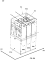
- the present application relates to a multi-pole, multi-way switchgear having respective poles of each switching device of the switchgear arranged in a depth-wise orientation.
- Switchgears are switching mechanisms used to control and protect electrical equipment, such as equipment operated by utilities, commercial building owners, and operators of distributed renewable generation assets such as solar farms and wind turbines.
- Such switchgears include various medium voltage devices (e.g., devices rated for 12kV or 24kV) for a range of applications, such as a ring main unit (RMU).
- RMU ring main unit
- Document US 9466955B2 discloses a knife switch including an operator device for moving a contact knife between a first open position and a second position in electrical contact with a contact element.
- a free end of the contact knife is provided with a dynamic electric field control device including an electrically conductive element.
- the switchgear further comprises a housing having first and second side walls, wherein the switching devices are arranged along the first axis between the first and second side walls of housing.
- each disconnector blade is pivotably coupled to the respective switch, and wherein each disconnector blade is configured to rotate around the pivot from the first position to the second position, wherein the rotation is towards the second side wall of the housing.
- the second side wall comprises: an end insulator configured to contact, when the disconnector blades of the poles disposed proximate to the second side wall are in the second position, the second end of said disconnector blades; and/or an insulating sheet.
- the second side wall comprises two shields, each shield comprising a metallic plate covered in an insulating material, wherein when the disconnector blades of the poles disposed proximate to the second side wall are in the second position, the second end of said disconnector blades is disposed between the two shields.
- the switchgear further comprises a flexible link electrically connecting the first end of each disconnector blade and the moveable contact. This can facilitate movement of the disconnector blade.
- each disconnector blade is operated by a four-bar crank rocker mechanism.
- each disconnector and earthing switch is arranged between the respective switch and the shaft along a respective third axis perpendicular to the first and second axes.
- a plane in which disconnector blade rotates is offset from an operating axis of the respective switch. This offset can facilitate a greater degree of movement of the disconnector blade of the disconnector and earthing switch, which facilitates improved clearance between the first, second and third positions of the disconnector blade. Dielectric performance may therefore be improved.
- the switchgear further comprises a plurality of busbar assemblies, each busbar assembly comprising a plurality of main busbars and a plurality of branch busbars alternately arranged along the first axis, each main busbar extending parallel to the first axis to electrically connect corresponding poles of adjacent switching devices, wherein, when the disconnector blades are in the first position, the second end of each disconnector blade is electrically connected to a respective branch busbar, wherein each branch busbar is electrically coupled to a respective main busbar to provide a conduction path between adjacent switching devices.
- each branch busbar comprises a partially spherical end. This can help reduce end effects.
- each of the plurality busbar assemblies is insulated at either end.
- each respective switch comprises a vacuum interrupter, wherein the moveable contact of the vacuum interrupter is moveable by the actuating mechanism and is arranged between the fixed contact of the vacuum interrupter and the shaft of the actuating mechanism.
- the first switching device is a first load break switch LBS
- the second switching device is a second load break switch LBS
- the third switching device is a vacuum circuit breaker VCB.
- the insulating material/sheets can be provided within the enclosure of the VCB, which can be formed in part by the second side wall of the housing.
- any other types and combinations of switches or switching devices can be used.
- the disconnector and earthing switch is a three-position switch, or 3PS.
- the 3PS is an off load 3PS switch.
- one off load three-position disconnector and earthing switch is in series with a vacuum circuit break VCB (an example implementation of a switching device) and two off load 3PS are in series with respective load break switches LBS (another example implementation of a switching device).
- the switchgear further comprises a plurality of disconnector and earthing switches, each disconnector and earthing switch associated with a respective one of the plurality of poles, and each disconnector and earthing switch having a disconnector blade pivotable around a first end of the disconnector blade between two or more different positions.
- the two or more positions comprise: a first position in which the disconnector and earthing switch is closed and the power supply is connected to the load through the disconnector blade; and a second position in which the power supply is disconnected from the load and a second end of the disconnector blade is electrically connected to an earthing contact.
- This can be implemented as a two-position earthing disconnection switch.
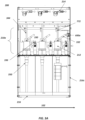
- a switchgear 200 (which is an example implementation of switchgear 100) also comprises a plurality of disconnector and earthing switches 330, each disconnector and earthing switch associated with a respective one of the plurality of poles 210.
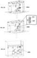
- Each disconnector and earthing switch has a disconnector blade 332 which is pivotably connected, at a first end 342, to the associated switch. The disconnector blade is arranged to pivot at this first end between three different positions, as is further illustrated in Figure 4 .
- the switching compartment described herein is air insulated, however any other insulating medium which fulfils the required dielectric / thermal requirements (such as a vacuum, pressurised air, SF6 (sulphur hexafluoride) or other gaseous dielectric medium, or inert gas) may be provided within the switching compartment.
- any other insulating medium which fulfils the required dielectric / thermal requirements such as a vacuum, pressurised air, SF6 (sulphur hexafluoride) or other gaseous dielectric medium, or inert gas
- the VI housing acts as a support for the hinge or pivot point at the first end 342 of the disconnector blade 332 (see e.g., Figure 3B ).
- the first end of each disconnector blade is pivotably coupled to the respective switch 212.
- the first end of the disconnector blade 342 can be pivotably coupled to the switch between the moveable contact and the shaft 214.
- the first end of the disconnector blade 342 is pivotably coupled to a top of the VI housing which surrounds the fixed and moveable contacts of the switch.
- the disconnector and earthing switch is described with reference to a 3PS disconnector and earthing switch.
- the switchgear architecture described can be implemented without any disconnector and earthing switch, or with any disconnector and earthing switch having two or more positions.
- the disconnector blade 332 is arranged in a first position in which in which the 3PS disconnector and earthing switch is closed and the power supply is connected to the load through the disconnector blade (via a busbar, as discussed further below). This current path is shown further in Figure 3B . In this first position, current flows through the switchgear 200 via the fixed and moveable contacts and the disconnector blade.
- each disconnector and earthing switch comprises two or more disconnector blades. By using two disconnector blades, two parallel paths are created for current flow. This can help to improve thermal performance.
- each disconnector and earthing switch comprises a single disconnector blade.
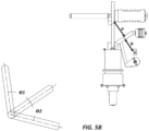
- the offset, d also allows a compression spring to be connected to and placed between the two blades. The compression spring acts to pull both disconnector blades inward toward one another.
- the compression spring is arranged to generate an inward force that will help counter repulsive forces and pull the blades together so they remain in good electrical connection with the one and earth contacts. Electrical contact may therefore be improved.
- the offset allows the total degree of rotation of the disconnector blade of each switch 212 to be greater than 90 degrees.
- theta_1 is between 50 and 80 degrees, optionally between 55 and 75 degrees, optionally between 60 and 70 degrees, optionally about 63 degrees.
- theta_2 is between 30 and 60 degrees, optionally between 35 and 55 degrees, optionally between 40 and 50 degrees, optionally about 48 degrees.
- the clearance a between the first, "on", position and the second, "off” or isolation, position is between 90 and 140 mm, optionally between 100 and 130 mm, optionally between 110 and 120 mm, optionally about 113 mm.
- the clearance b between the second, "off" or isolation, position and the third, earth, position is between 60 and 110 mm, optionally between 70 and 100 mm, optionally between 80 and 90 mm, optionally about 85 mm.
- the particular degrees of rotation theta_1, theta_2 and the particular clearances a , b will depend on the specific configuration and dimensions of the switchgear 100, 200.
- one or more insulating or isolating features may be provided to improve electrical safety during the isolation, second, position. These features may be provided individually, or in combination with one or more other insulating features (including features not described herein). It will be understood that the second end 334 of the disconnector blade 332 can be shaped to accommodate the insulating/isolating features described in Figure 6 whilst still allowing movement of the disconnector blade from the second position to the third, earthed, position of Figure 4C .
- the second side wall 216a of the housing comprises one or more shields 600b.
- the second end 334 of said disconnector blades is disposed between the two shields 600b.
- This shield 600b reduces field end effects at the second end 334 of the disconnector blade 332.
- the use of an insulating core means the high field is partly contained in the insulating material, which improves dielectric performance as compared to a high electric field in air.
- the second side wall 216a of the housing comprises an insulating sheet 600c.
- the insulating sheet 600c can be formed from any suitable insulating material.
- the insulating sheet 600c need not contact the second end 334 of the disconnector blades of the poles disposed proximate to the second side wall (e.g., the poles of the third switching device 208c) are in the second position.
- the presence of the insulating sheet 600c acts as an obstruction to breakdown electrical current paths and can help avoid dielectric failure, thereby improving dielectric performance as compared to an equivalent switchgear with no insulating sheet 600c.
- busbar assembly 700 suitable for use with the switchgear 100, 200 is described.
- the busbar assembly 700 comprises a plurality of cylindrical main busbars 770, each comprising an inner hole extending through a length of the main busbar.
- the busbar assembly also comprises a plurality of branch busbars 772.
- a first end of each branch busbar comprises a hole 774 and a second end of each branch busbar comprises a spherical portion 776.
- the use of a spherical (i.e., curved) portion at the second end of the branch busbar 772 acts to reduce or avoid high fields at the second end of the branch busbar.
- the second end of the disconnector blade contacts a corresponding branch busbar in the first, on, position to connect the power supply and the load.
- the switchgear comprises a housing comprising first 216a and second 216b side walls offset along the first direction 782.
- the first side wall 216a comprises a first insulating mount 784 configured to threadably engage with the first end of the threaded rod 778.
- the second side wall 216b comprises a second insulating mount 786 configured to threadably engage with the second end of the threaded rod 778.
- the first insulating mount 784 is an insulating bush.
- the second insulating mount 786 is an epoxy insulator.
- other insulating mounts may be used, as required by the size and use/application of the switchgear.
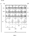
- FIG. 8 a plan view of a switchgear 100, 200 in accordance with the current disclosure and comprising a busbar assembly 700 is described.
- the example of Figure 8 is a three-way switchgear having three switching devices 208: a first switching device 208a, a second switching device 208b, and a third switching device 208c.
- the switching devices are provided between first 216a and second 216b side walls of the switchgear housing, arranged along a first axis 102.
- a distance d1 between the first and second switching devices 208a, 208b is equal to a distance between the second and third switching devices 208b, 208c.
- a distance d2 between the third switching device and the second side wall 216b of the housing is less than d1.
- a distance d3 between the first switching device and the first side wall 216a of the housing is less than d1 and less than d2.
- the dimension d2 is limited by the need to provide sufficient insulation/isolation during the second, "off" position of the 3PS disconnector and earthing switch 330.
- the insulating feature(s) described with reference to Figure 6 facilitate a smaller dimension d2, which helps provide a more compact switchgear.
- each of the first, second and third switching devices comprise three poles 210a, 210b, 210c arranged in a depth-wise or transverse direction 104 (as in Figure 1B ).
- the switching devices 208 are arranged along a first axis (102), and the plurality of poles 210 of each switching device are arranged along a respective second axis (104) perpendicular to the first axis.
- Each of the plurality of poles 210 is associated with a respective switch 212 having a fixed contact and a moveable contact.
- Each of the plurality of poles 210 is also associated with an disconnector and earthing switch 330, as discussed with reference to Figure 3 .
- a plurality of busbar assemblies 700 as described with reference to Figure 7 are arranged between the operating shaft 214 (not shown) and the switches 212.
- the busbar assemblies 700 are insulated at each end and coupled to the housing of the switchgear, as described with reference to Figure 7B .
- Each busbar assembly comprises a plurality of main busbars 770 and a plurality of branch busbars 772 alternately arranged along the first axis 102.
- each busbar assembly 700 comprises two main busbars 770, each main busbar extending parallel to the first axis to electrically connect corresponding poles 210 of adjacent switching devices 208.
- one main busbar connects pole 210a of switch/device 208a and pole 210a of switch/device 208b and another main busbar connects pole 210a of switch/device 208b and pole 210a of switch/device 208c.
- each branch busbar there are three branch busbars per assembly (alternately arranged with the main busbars along the first axis).
- the busbar assemblies 700 are arranged such that, when the disconnector blades are in the first position, the second end 334 of each disconnector blade 332 is electrically connected to the second end of the respective branch busbar 772.
- the branch busbars can each have a partially spherical second end, as described with reference to Figure 7C , to reduce or avoid high fields at the end of the branch busbar.
- Each branch busbar is electrically coupled to the main busbars of the respective assembly to provide a conduction path between adjacent switching devices.
Landscapes
- Engineering & Computer Science (AREA)
- Power Engineering (AREA)
- Gas-Insulated Switchgears (AREA)
Claims (14)
- Schaltanlage (100, 200), umfassend:eine Vielzahl von Schaltvorrichtungen (208), konfiguriert, um eine Stromversorgung von einer Last zu trennen, wobei jede Schaltvorrichtung umfasst:eine Vielzahl von Polen (210), wobei jeder Pol mit einem jeweiligen Schalter (212) verbunden ist, der einen festen Kontakt und einen beweglichen Kontakt aufweist, undeinen Betätigungsmechanismus, der eine Welle (214) umfasst, wobei die Welle so konfiguriert ist, dass sie sich dreht, um eine externe Eingabekraft zu übertragen, um den beweglichen Kontakt zu bewegen und die Schalter der Schaltvorrichtung zu öffnen oder zu schließen;wobei:die Vielzahl der Schaltvorrichtungen entlang einer ersten Achse (102) angeordnet ist,die Vielzahl der Pole jeder Schaltvorrichtung entlang einer jeweiligen zweiten Achse (104) angeordnet ist, die senkrecht zur ersten Achse verläuft, undjede Welle senkrecht zur ersten Achse angeordnet ist und zur Drehung um eine zu den zweiten Achsen parallele Drehachse konfiguriert ist; undeine Vielzahl von Trenn- und Erdungsschaltern (330), wobei jeder Trenn- und Erdungsschalter mit einem entsprechenden der Vielzahl von Polen verbunden ist und jeder Trenn- und Erdungsschalter ein Trennblatt (332) aufweist, die um ein erstes Ende (342) des Trennblattes zwischen drei verschiedenen Positionen schwenkbar ist, wobei die drei Positionen Folgendes umfassen:eine erste Position, in der der Trenn- und Erdungsschalter geschlossen ist und die Stromversorgung über das Trennblatt mit der Last verbunden ist;eine zweite, isolierte Position, in der der Trenn- und Erdungsschalter geöffnet ist und die Stromversorgung von der Last getrennt ist; undeine dritte Position, in der die Stromversorgung von der Last getrennt ist und ein zweites Ende (334) des Trennblattes elektrisch mit einem Erdungskontakt (336) verbunden ist, dadurch gekennzeichnet, dass das erste Ende des Trennblattes schwenkbar mit dem jeweiligen Schalter gekoppelt ist.
- Schaltanlage nach Anspruch 1, ferner umfassend ein Gehäuse (216), das eine erste (216a) und eine zweite (216b) Seitenwand aufweist,
wobei die Schaltvorrichtungen entlang der ersten Achse zwischen der ersten und zweiten Seitenwand des Gehäuses angeordnet sind. - Schaltanlage nach Anspruch 2, wobei das erste jedes Trennblattes schwenkbar mit dem jeweiligen Schalter gekoppelt ist,
und wobei jedes Trennblatt so konfiguriert ist, dass sie sich um den Drehpunkt von der ersten Position zur zweiten Position dreht, wobei die Drehung in Richtung der zweiten Seitenwand des Gehäuses erfolgt. - Schaltanlage nach Anspruch 3, wobei die zweite Seitenwand Folgendes umfasst:einen Endisolator (600a), der so konfiguriert ist, dass er mit dem zweiten Ende der Trennblätter in Kontakt kommt, wenn die Trennblätter der Pole, die in der Nähe der zweiten Seitenwand angeordnet sind, sich in der zweiten Position befinden; und/odereine Isolierlage (600c).
- Schaltanlage nach Anspruch 3, wobei die zweite Seitenwand zwei Abschirmungen (600b) umfasst, wobei jede Abschirmung eine Metallplatte (610) umfasst, die mit einem isolierenden Material (620) bedeckt ist, wobei, wenn die Trennblätter der in der Nähe der zweiten Seitenwand angeordneten Pole in der zweiten Position sind, das zweite Ende der Trennblätter zwischen den beiden Abschirmungen angeordnet ist.
- Schaltanlage nach einem der Ansprüche 1 bis 5, ferner umfassend eine flexible Verbindung (340), die das erste Ende jedes Trennblattes und den beweglichen Kontakt elektrisch miteinander verbindet.
- Schaltanlage nach Anspruch 6, wobei jeder Trenn- und Erdungsschalter zwischen dem jeweiligen Schalter und der Welle entlang einer jeweiligen dritten Achse (106) angeordnet ist, die senkrecht zur ersten und zweiten Achse verläuft.
- Schaltanlage nach einem der Ansprüche 1 bis 7, wobei jedes Trennblatt durch einen viergliedrigen Kurbelwippmechanismus (348) betrieben wird.
- Schaltanlage nach einem der Ansprüche 1 bis 8, wobei eine Ebene (108), in der sich das Trennblatt dreht, von einer Betriebsachse des jeweiligen Schalters versetzt ist.
- Schaltanlage nach einem der Ansprüche 1 bis 9, ferner umfassend eine Vielzahl von Sammelschienenanordnungen (700), wobei jede Sammelschienenanordnung eine Vielzahl von Hauptsammelschienen (770) und eine Vielzahl von Zweigsammelschienen (772) umfasst, die abwechselnd entlang der ersten Achse angeordnet sind,wobei sich jede Hauptsammelschiene parallel zur ersten Achse erstreckt, um entsprechende Pole von benachbarten Schaltvorrichtungen elektrisch zu verbinden,wobei, wenn sich die Trennblätter in der ersten Position befinden, das zweite Ende jedes Trennblattes elektrisch mit einer jeweiligen Zweigsammelschiene verbunden ist,wobei jede Zweigsammelschiene elektrisch mit einer entsprechenden Hauptsammelschiene gekoppelt ist, um einen Leitungspfad zwischen benachbarten Schaltvorrichtungen bereitzustellen.
- Schaltanlage nach Anspruch 10, wobei jede Zweigsammelschiene ein teilweise kugelförmiges Ende umfasst.
- Schaltanlage nach Anspruch 10 oder 11, wobei jede der Vielzahl von Sammelschienenanordnungen an beiden Enden isoliert ist.
- Schaltanlage nach einem der vorstehenden Ansprüche, wobei jeder jeweilige Schalter einen Vakuumschalter umfasst, wobei der bewegliche Kontakt des Vakuumschalters durch den Betätigungsmechanismus bewegt werden kann und zwischen dem festen Kontakt des Vakuumschalters und der Welle des Betätigungsmechanismus angeordnet ist.
- Schaltanlage nach einem der vorstehenden Ansprüche, wobei es sich bei der Schaltanlage um eine Drei-Wege-Schaltanlage handelt und die Vielzahl der Schaltvorrichtungen aus folgenden Elementen besteht:eine erste Schaltvorrichtung (208a);eine zweite Schaltvorrichtung (208b); undeine dritte Schaltvorrichtung (208c),wobei jede der ersten, zweiten und dritten Schaltvorrichtung drei Pole umfasst.
Applications Claiming Priority (2)
| Application Number | Priority Date | Filing Date | Title |
|---|---|---|---|
| IN202311016936 | 2023-03-14 | ||
| GB2306483.5A GB2628190A (en) | 2023-03-14 | 2023-05-02 | Switchgear architecture |
Publications (2)
| Publication Number | Publication Date |
|---|---|
| EP4432324A1 EP4432324A1 (de) | 2024-09-18 |
| EP4432324B1 true EP4432324B1 (de) | 2025-07-09 |
Family
ID=90364248
Family Applications (1)
| Application Number | Title | Priority Date | Filing Date |
|---|---|---|---|
| EP24162508.6A Active EP4432324B1 (de) | 2023-03-14 | 2024-03-08 | Schaltanlagenarchitektur |
Country Status (4)
| Country | Link |
|---|---|
| US (1) | US20240313512A1 (de) |
| EP (1) | EP4432324B1 (de) |
| JP (1) | JP7766127B2 (de) |
| PL (1) | PL4432324T3 (de) |
Family Cites Families (11)
| Publication number | Priority date | Publication date | Assignee | Title |
|---|---|---|---|---|
| JP4439035B2 (ja) | 1999-05-26 | 2010-03-24 | 三菱電機株式会社 | ガス封入開閉装置 |
| DE102005009207A1 (de) * | 2005-02-25 | 2006-08-31 | Abb Technology Ag | Schaltanlage |
| US7854620B2 (en) * | 2007-02-20 | 2010-12-21 | Cooper Technologies Company | Shield housing for a separable connector |
| US8878092B2 (en) * | 2009-06-25 | 2014-11-04 | Mitsubishi Electric Corporation | Gas-insulated switchgear |
| JP5298089B2 (ja) | 2010-08-20 | 2013-09-25 | 株式会社日立製作所 | 開閉器,開閉器ユニット,スイッチギヤ及びスイッチギヤを搭載した風車 |
| US9136077B2 (en) * | 2011-04-14 | 2015-09-15 | Impact Power, Inc. | Three-phase, multi-way vacuum interrupter switchgear with internal ground switches |
| JP5921269B2 (ja) * | 2012-03-14 | 2016-05-24 | 株式会社日立製作所 | スイッチギヤ |
| WO2014154292A1 (en) * | 2013-03-28 | 2014-10-02 | Abb Technology Ltd | A switch assembly, a switching device comprising a switch assembly, a switchgear comprising a switching device and a method for cooling |
| EP2979290B1 (de) * | 2013-03-28 | 2016-07-13 | ABB Technology Ltd | Messerschalter, schaltvorrichtung mit einem messerschalter und schaltanlage |
| CN104254953B (zh) * | 2013-04-26 | 2017-09-12 | 通用电气公司 | 包括释压部件的开关装置壳体 |
| US9622374B2 (en) * | 2014-08-08 | 2017-04-11 | General Electric Company | Electrical equipment and a method of manufacturing |
-
2024
- 2024-03-08 US US18/600,160 patent/US20240313512A1/en active Pending
- 2024-03-08 JP JP2024036241A patent/JP7766127B2/ja active Active
- 2024-03-08 PL PL24162508.6T patent/PL4432324T3/pl unknown
- 2024-03-08 EP EP24162508.6A patent/EP4432324B1/de active Active
Also Published As
| Publication number | Publication date |
|---|---|
| PL4432324T3 (pl) | 2025-09-15 |
| EP4432324A1 (de) | 2024-09-18 |
| JP2024132958A (ja) | 2024-10-01 |
| JP7766127B2 (ja) | 2025-11-07 |
| US20240313512A1 (en) | 2024-09-19 |
Similar Documents
| Publication | Publication Date | Title |
|---|---|---|
| US7829814B2 (en) | Vacuum circuit interrupter grounding assembly | |
| EP2296160B1 (de) | Vakuumisoliertes Schaltgetriebe | |
| CN103367016B (zh) | 电气开关装置、电气设备以及开关柜 | |
| US6259051B1 (en) | Vacuum switch and a vacuum switchgear using the same | |
| CN1237679C (zh) | 一种气体绝缘开关装置 | |
| KR101463374B1 (ko) | 스위칭 디바이스 및 개폐기 | |
| KR101562482B1 (ko) | 스위칭 디바이스 및 개폐기 | |
| JPS6361842B2 (de) | ||
| US7250583B2 (en) | Gas-insulated switchgear device | |
| EP2645378B1 (de) | Elektrische Vorrichtung mit Isolatoren | |
| EP1589625B1 (de) | Gasisolierte Schaltanlage | |
| KR20200029047A (ko) | 가스 절연되는 스위치기어용 회로차단기 | |
| EP3843117B1 (de) | Lasttrennschalter ohne sf6-gas mit einem vakuumleistungsschalter für mittelspannungsschaltanlagen | |
| EP4432324A1 (de) | Schaltanlagenarchitektur | |
| JP3891680B2 (ja) | スイッチギヤ | |
| GB2628189A (en) | Disconnector and Earthing Switch with Telescopic Contact | |
| GB2628190A (en) | Switchgear architecture | |
| US5696364A (en) | Combined interrupter disconnect switch blade for high voltage switch | |
| EP4432323B1 (de) | Trennschalter und erdungsschalter mit teleskopischem kontakt | |
| CN110945613A (zh) | 用于气体绝缘开关设备的隔离开关极 | |
| US4256934A (en) | Disconnecting switch arrangement | |
| KR101279894B1 (ko) | 고체 절연 스위치기어용 개폐기 | |
| CN119171319B (zh) | 一种24kv开关柜 | |
| JPH1189027A (ja) | スイッチギヤ | |
| CN115000817B (zh) | 环网柜及其三工位开关 |
Legal Events
| Date | Code | Title | Description |
|---|---|---|---|
| PUAI | Public reference made under article 153(3) epc to a published international application that has entered the european phase |
Free format text: ORIGINAL CODE: 0009012 |
|
| STAA | Information on the status of an ep patent application or granted ep patent |
Free format text: STATUS: THE APPLICATION HAS BEEN PUBLISHED |
|
| AK | Designated contracting states |
Kind code of ref document: A1 Designated state(s): AL AT BE BG CH CY CZ DE DK EE ES FI FR GB GR HR HU IE IS IT LI LT LU LV MC ME MK MT NL NO PL PT RO RS SE SI SK SM TR |
|
| STAA | Information on the status of an ep patent application or granted ep patent |
Free format text: STATUS: REQUEST FOR EXAMINATION WAS MADE |
|
| 17P | Request for examination filed |
Effective date: 20241216 |
|
| GRAP | Despatch of communication of intention to grant a patent |
Free format text: ORIGINAL CODE: EPIDOSNIGR1 |
|
| STAA | Information on the status of an ep patent application or granted ep patent |
Free format text: STATUS: GRANT OF PATENT IS INTENDED |
|
| INTG | Intention to grant announced |
Effective date: 20250422 |
|
| GRAS | Grant fee paid |
Free format text: ORIGINAL CODE: EPIDOSNIGR3 |
|
| P01 | Opt-out of the competence of the unified patent court (upc) registered |
Free format text: CASE NUMBER: APP_20002/2025 Effective date: 20250426 |
|
| GRAA | (expected) grant |
Free format text: ORIGINAL CODE: 0009210 |
|
| STAA | Information on the status of an ep patent application or granted ep patent |
Free format text: STATUS: THE PATENT HAS BEEN GRANTED |
|
| AK | Designated contracting states |
Kind code of ref document: B1 Designated state(s): AL AT BE BG CH CY CZ DE DK EE ES FI FR GB GR HR HU IE IS IT LI LT LU LV MC ME MK MT NL NO PL PT RO RS SE SI SK SM TR |
|
| REG | Reference to a national code |
Ref country code: GB Ref legal event code: FG4D |
|
| REG | Reference to a national code |
Ref country code: CH Ref legal event code: EP |
|
| REG | Reference to a national code |
Ref country code: IE Ref legal event code: FG4D |
|
| REG | Reference to a national code |
Ref country code: DE Ref legal event code: R096 Ref document number: 602024000282 Country of ref document: DE |
|
| REG | Reference to a national code |
Ref country code: SE Ref legal event code: TRGR |
|
| REG | Reference to a national code |
Ref country code: NL Ref legal event code: FP |
|
| PG25 | Lapsed in a contracting state [announced via postgrant information from national office to epo] |
Ref country code: PT Free format text: LAPSE BECAUSE OF FAILURE TO SUBMIT A TRANSLATION OF THE DESCRIPTION OR TO PAY THE FEE WITHIN THE PRESCRIBED TIME-LIMIT Effective date: 20251110 |
|
| REG | Reference to a national code |
Ref country code: AT Ref legal event code: MK05 Ref document number: 1812707 Country of ref document: AT Kind code of ref document: T Effective date: 20250709 |
|
| PG25 | Lapsed in a contracting state [announced via postgrant information from national office to epo] |
Ref country code: IS Free format text: LAPSE BECAUSE OF FAILURE TO SUBMIT A TRANSLATION OF THE DESCRIPTION OR TO PAY THE FEE WITHIN THE PRESCRIBED TIME-LIMIT Effective date: 20251109 |
|
| PG25 | Lapsed in a contracting state [announced via postgrant information from national office to epo] |
Ref country code: NO Free format text: LAPSE BECAUSE OF FAILURE TO SUBMIT A TRANSLATION OF THE DESCRIPTION OR TO PAY THE FEE WITHIN THE PRESCRIBED TIME-LIMIT Effective date: 20251009 |
|
| REG | Reference to a national code |
Ref country code: LT Ref legal event code: MG9D |
|
| PG25 | Lapsed in a contracting state [announced via postgrant information from national office to epo] |
Ref country code: AT Free format text: LAPSE BECAUSE OF FAILURE TO SUBMIT A TRANSLATION OF THE DESCRIPTION OR TO PAY THE FEE WITHIN THE PRESCRIBED TIME-LIMIT Effective date: 20250709 |
|
| PG25 | Lapsed in a contracting state [announced via postgrant information from national office to epo] |
Ref country code: FI Free format text: LAPSE BECAUSE OF FAILURE TO SUBMIT A TRANSLATION OF THE DESCRIPTION OR TO PAY THE FEE WITHIN THE PRESCRIBED TIME-LIMIT Effective date: 20250709 |
|
| PG25 | Lapsed in a contracting state [announced via postgrant information from national office to epo] |
Ref country code: HR Free format text: LAPSE BECAUSE OF FAILURE TO SUBMIT A TRANSLATION OF THE DESCRIPTION OR TO PAY THE FEE WITHIN THE PRESCRIBED TIME-LIMIT Effective date: 20250709 |
|
| PG25 | Lapsed in a contracting state [announced via postgrant information from national office to epo] |
Ref country code: GR Free format text: LAPSE BECAUSE OF FAILURE TO SUBMIT A TRANSLATION OF THE DESCRIPTION OR TO PAY THE FEE WITHIN THE PRESCRIBED TIME-LIMIT Effective date: 20251010 |
|
| PG25 | Lapsed in a contracting state [announced via postgrant information from national office to epo] |
Ref country code: LV Free format text: LAPSE BECAUSE OF FAILURE TO SUBMIT A TRANSLATION OF THE DESCRIPTION OR TO PAY THE FEE WITHIN THE PRESCRIBED TIME-LIMIT Effective date: 20250709 |
|
| PG25 | Lapsed in a contracting state [announced via postgrant information from national office to epo] |
Ref country code: BG Free format text: LAPSE BECAUSE OF FAILURE TO SUBMIT A TRANSLATION OF THE DESCRIPTION OR TO PAY THE FEE WITHIN THE PRESCRIBED TIME-LIMIT Effective date: 20250709 |
|
| PG25 | Lapsed in a contracting state [announced via postgrant information from national office to epo] |
Ref country code: RS Free format text: LAPSE BECAUSE OF FAILURE TO SUBMIT A TRANSLATION OF THE DESCRIPTION OR TO PAY THE FEE WITHIN THE PRESCRIBED TIME-LIMIT Effective date: 20251009 |
|
| PG25 | Lapsed in a contracting state [announced via postgrant information from national office to epo] |
Ref country code: ES Free format text: LAPSE BECAUSE OF FAILURE TO SUBMIT A TRANSLATION OF THE DESCRIPTION OR TO PAY THE FEE WITHIN THE PRESCRIBED TIME-LIMIT Effective date: 20250709 |
|
| PG25 | Lapsed in a contracting state [announced via postgrant information from national office to epo] |
Ref country code: SM Free format text: LAPSE BECAUSE OF FAILURE TO SUBMIT A TRANSLATION OF THE DESCRIPTION OR TO PAY THE FEE WITHIN THE PRESCRIBED TIME-LIMIT Effective date: 20250709 |
|
| PGFP | Annual fee paid to national office [announced via postgrant information from national office to epo] |
Ref country code: SE Payment date: 20260219 Year of fee payment: 3 |
|
| PG25 | Lapsed in a contracting state [announced via postgrant information from national office to epo] |
Ref country code: DK Free format text: LAPSE BECAUSE OF FAILURE TO SUBMIT A TRANSLATION OF THE DESCRIPTION OR TO PAY THE FEE WITHIN THE PRESCRIBED TIME-LIMIT Effective date: 20250709 |
|
| PGFP | Annual fee paid to national office [announced via postgrant information from national office to epo] |
Ref country code: DE Payment date: 20260219 Year of fee payment: 3 |
|
| PG25 | Lapsed in a contracting state [announced via postgrant information from national office to epo] |
Ref country code: IT Free format text: LAPSE BECAUSE OF FAILURE TO SUBMIT A TRANSLATION OF THE DESCRIPTION OR TO PAY THE FEE WITHIN THE PRESCRIBED TIME-LIMIT Effective date: 20250709 |
|
| PG25 | Lapsed in a contracting state [announced via postgrant information from national office to epo] |
Ref country code: CZ Free format text: LAPSE BECAUSE OF FAILURE TO SUBMIT A TRANSLATION OF THE DESCRIPTION OR TO PAY THE FEE WITHIN THE PRESCRIBED TIME-LIMIT Effective date: 20250709 |
|
| PGFP | Annual fee paid to national office [announced via postgrant information from national office to epo] |
Ref country code: PL Payment date: 20260219 Year of fee payment: 3 |
|
| PG25 | Lapsed in a contracting state [announced via postgrant information from national office to epo] |
Ref country code: SK Free format text: LAPSE BECAUSE OF FAILURE TO SUBMIT A TRANSLATION OF THE DESCRIPTION OR TO PAY THE FEE WITHIN THE PRESCRIBED TIME-LIMIT Effective date: 20250709 Ref country code: EE Free format text: LAPSE BECAUSE OF FAILURE TO SUBMIT A TRANSLATION OF THE DESCRIPTION OR TO PAY THE FEE WITHIN THE PRESCRIBED TIME-LIMIT Effective date: 20250709 |
|
| PLBE | No opposition filed within time limit |
Free format text: ORIGINAL CODE: 0009261 |
|
| STAA | Information on the status of an ep patent application or granted ep patent |
Free format text: STATUS: NO OPPOSITION FILED WITHIN TIME LIMIT |