EP4432421A1 - Gassammelvorrichtung - Google Patents
Gassammelvorrichtung Download PDFInfo
- Publication number
- EP4432421A1 EP4432421A1 EP23872739.0A EP23872739A EP4432421A1 EP 4432421 A1 EP4432421 A1 EP 4432421A1 EP 23872739 A EP23872739 A EP 23872739A EP 4432421 A1 EP4432421 A1 EP 4432421A1
- Authority
- EP
- European Patent Office
- Prior art keywords
- unit
- battery
- jig
- collecting apparatus
- chamber body
- Prior art date
- Legal status (The legal status is an assumption and is not a legal conclusion. Google has not performed a legal analysis and makes no representation as to the accuracy of the status listed.)
- Granted
Links
Images
Classifications
-
- H—ELECTRICITY
- H01—ELECTRIC ELEMENTS
- H01M—PROCESSES OR MEANS, e.g. BATTERIES, FOR THE DIRECT CONVERSION OF CHEMICAL ENERGY INTO ELECTRICAL ENERGY
- H01M10/00—Secondary cells; Manufacture thereof
- H01M10/42—Methods or arrangements for servicing or maintenance of secondary cells or secondary half-cells
-
- G—PHYSICS
- G01—MEASURING; TESTING
- G01N—INVESTIGATING OR ANALYSING MATERIALS BY DETERMINING THEIR CHEMICAL OR PHYSICAL PROPERTIES
- G01N1/00—Sampling; Preparing specimens for investigation
- G01N1/02—Devices for withdrawing samples
- G01N1/22—Devices for withdrawing samples in the gaseous state
- G01N1/2226—Sampling from a closed space, e.g. food package, head space
-
- H—ELECTRICITY
- H01—ELECTRIC ELEMENTS
- H01M—PROCESSES OR MEANS, e.g. BATTERIES, FOR THE DIRECT CONVERSION OF CHEMICAL ENERGY INTO ELECTRICAL ENERGY
- H01M10/00—Secondary cells; Manufacture thereof
- H01M10/42—Methods or arrangements for servicing or maintenance of secondary cells or secondary half-cells
- H01M10/4285—Testing apparatus
-
- H—ELECTRICITY
- H01—ELECTRIC ELEMENTS
- H01M—PROCESSES OR MEANS, e.g. BATTERIES, FOR THE DIRECT CONVERSION OF CHEMICAL ENERGY INTO ELECTRICAL ENERGY
- H01M10/00—Secondary cells; Manufacture thereof
- H01M10/42—Methods or arrangements for servicing or maintenance of secondary cells or secondary half-cells
- H01M10/52—Removing gases inside the secondary cell, e.g. by absorption
-
- H—ELECTRICITY
- H01—ELECTRIC ELEMENTS
- H01M—PROCESSES OR MEANS, e.g. BATTERIES, FOR THE DIRECT CONVERSION OF CHEMICAL ENERGY INTO ELECTRICAL ENERGY
- H01M50/00—Constructional details or processes of manufacture of the non-active parts of electrochemical cells other than fuel cells, e.g. hybrid cells
- H01M50/30—Arrangements for facilitating escape of gases
- H01M50/342—Non-re-sealable arrangements
- H01M50/3425—Non-re-sealable arrangements in the form of rupturable membranes or weakened parts, e.g. pierced with the aid of a sharp member
-
- G—PHYSICS
- G01—MEASURING; TESTING
- G01N—INVESTIGATING OR ANALYSING MATERIALS BY DETERMINING THEIR CHEMICAL OR PHYSICAL PROPERTIES
- G01N1/00—Sampling; Preparing specimens for investigation
- G01N1/02—Devices for withdrawing samples
- G01N1/22—Devices for withdrawing samples in the gaseous state
- G01N1/2226—Sampling from a closed space, e.g. food package, head space
- G01N2001/2238—Sampling from a closed space, e.g. food package, head space the gas being compressed or pressurized
-
- G—PHYSICS
- G01—MEASURING; TESTING
- G01N—INVESTIGATING OR ANALYSING MATERIALS BY DETERMINING THEIR CHEMICAL OR PHYSICAL PROPERTIES
- G01N1/00—Sampling; Preparing specimens for investigation
- G01N1/02—Devices for withdrawing samples
- G01N1/22—Devices for withdrawing samples in the gaseous state
- G01N1/2226—Sampling from a closed space, e.g. food package, head space
- G01N2001/2241—Sampling from a closed space, e.g. food package, head space purpose-built sampling enclosure for emissions
-
- Y—GENERAL TAGGING OF NEW TECHNOLOGICAL DEVELOPMENTS; GENERAL TAGGING OF CROSS-SECTIONAL TECHNOLOGIES SPANNING OVER SEVERAL SECTIONS OF THE IPC; TECHNICAL SUBJECTS COVERED BY FORMER USPC CROSS-REFERENCE ART COLLECTIONS [XRACs] AND DIGESTS
- Y02—TECHNOLOGIES OR APPLICATIONS FOR MITIGATION OR ADAPTATION AGAINST CLIMATE CHANGE
- Y02E—REDUCTION OF GREENHOUSE GAS [GHG] EMISSIONS, RELATED TO ENERGY GENERATION, TRANSMISSION OR DISTRIBUTION
- Y02E60/00—Enabling technologies; Technologies with a potential or indirect contribution to GHG emissions mitigation
- Y02E60/10—Energy storage using batteries
Definitions
- the present disclosure relates to a gas collecting apparatus, and particularly to a gas collecting apparatus capable of accurately and stably delivering collected gas to a gas analysis apparatus by automating loading, unloading, and punching of a battery.
- a secondary battery is a battery which can be used repeatedly through a discharging process in which chemical energy is converted into electrical energy and a charging process in the opposite direction to the discharging process and which includes nickelcadmium (Ni-Cd) batteries, nickel-metal hydride (Ni-MH) batteries, lithium-metal batteries, lithium-ion (Li-ion) batteries, and lithium-ion polymer batteries.
- Ni-Cd nickelcadmium
- Ni-MH nickel-metal hydride
- lithium-metal batteries lithium-ion batteries
- lithium-ion polymer batteries lithium-ion polymer batteries.
- lithium secondary batteries having high energy density and voltage, long cycle life, and a low self-discharge rate have been commercialized and widely used.
- the lithium secondary battery degrades while generating a large amount of gas due to electrolyte decomposition as repeated charging and discharging progresses, and this aspect appears differently depending on the design and use form of the battery. Therefore, it is essential to infer a deterioration mechanism of a battery by analyzing gas generated inside the battery during a battery development process.
- a method for collecting gas generated inside a secondary battery a method in which, when a battery is accommodated in a diffusion chamber with an airtight space formed therein, an opening for gas discharge is formed in the battery case, and then the gas discharged through the opening is diffused into the diffusion chamber, the diffused gas is collected in a separate gas collecting container is used.
- a separate gas collecting container For high-concentration gas collection, it may be most desirable that there is no clearance between the battery and the inner space of the diffusion chamber.
- batteries are used in a wide range of industrial fields, and depending on various battery application environments and conditions, performance required for batteries also varies, and batteries can be designed in various specifications.
- the concentration of the gas delivered to an analyzer or stored in the gas collecting container varies greatly depending on the volume of the diffusion chamber, the size of the battery (target to be analyzed), and the amount of gas generated, which affects the analysis result.
- the present disclosure relates to a gas collecting apparatus, and is to provide a gas collecting apparatus capable of accurately and stably delivering collected gas to a gas analysis apparatus by automating loading, unloading, and punching of a battery.
- a gas collecting apparatus of the present disclosure may include
- a gas collecting apparatus of the present disclosure may be capable of precise and rapid gas collection by automating replacement of a jig unit, loading and unloading of a battery, and punching.
- the gas collecting apparatus of the present disclosure may determine whether punching is completed by measuring movement of a punching needle and an amount of pressure change, thereby preventing accidents such as an internal short circuit of the battery and ensuring safety during gas collection.
- a gas collecting apparatus of the present disclosure may include
- the chamber body unit when a longitudinal direction of the cylindrical battery is referred to as a first direction, the chamber body unit may extend in the first direction, the opening may be formed at the one end of the chamber body unit in the first direction, the boat unit may move linearly in the first direction by the first driving unit, a punching needle may be provided on the one side of the chamber cap unit at a location facing the cylindrical battery, and the first driving unit may move the boat unit toward the chamber cap unit to form a perforated hole in the cylindrical battery by the punching needle.
- the jig unit may be provided in a cylindrical shape extending in the first direction
- the cylindrical battery may be mounted in the jig unit so that an outer circumferential surface of the cylindrical battery is in close contact with an inner circumferential surface of the jig unit
- a needle insertion hole may be formed at one end in the first direction of the jig unit.
- an electrolyte storage groove may be formed on the inner circumferential surface of the jig unit, and the electrolyte storage groove may be located adjacent to a side wall where the needle insertion hole is located in an inner space of the jig unit.
- a first cylindrical battery may be mounted in a part of the plurality of jig units and a second cylindrical battery may be mounted in another part of the plurality of jig units, wherein the first cylindrical battery and the second cylindrical battery may be formed with different outer diameters, and the plurality of jig units may be all provided with the same outer diameter.
- the battery storage unit may include a battery storage track in which the plurality of jig units are stored in an aligned state, a battery discharge hole formed at one end of the battery storage track to discharge the plurality of jig units one by one, and an elastic door mounted on an edge of an inlet of the battery discharge hole to prevent the plurality of jig units from being separated from the battery storage unit with a restoring force, wherein the boat unit may move between an outer space of the chamber body unit and the battery accommodating space by the first driving unit, and the inlet of the battery discharge hole may be provided at a location spaced apart from the boat unit by a predetermined distance so as to face the boat unit in a state of being located in the outer space of the chamber body unit.
- the battery delivery unit may include a gripper configured to grip one jig unit exposed to the battery discharge hole among the plurality of jig units, a rotating member having one end to which the gripper is mounted and extending in a second direction perpendicular to the first direction, and a shaft member which is located between the battery discharge hole and the boat unit in the state of being located in the outer space of the chamber body unit and extends in the first direction, wherein the shaft member may be coupled with the rotating member, and the rotating member may rotate with respect to the shaft member serving as a rotation shaft.
- the first driving unit may include a power transmission bar extending in the first direction and penetrating the other end of the chamber body unit in the first direction to have one end inserted inside the chamber body unit, a moving member, wherein the boat unit is coupled to one side of the moving member and the one end of the power transmission bar is coupled to the other side of the moving member, a first fixing frame to which the chamber body unit is fixed, a first moving frame to which the power transmission bar is fixed and linearly moving in the first direction based on the first fixing frame, a shaft screwed with the first moving frame and coupled to the first fixing frame to be capable of idling, and an electric motor configured to rotate the first shaft.
- a sealing cover surrounding the power transmission bar may be provided inside the chamber body unit, and one end of the sealing cover may be fused to the other side of the moving member and the other end of the sealing cover may be fused to an inner wall of the other end side of the chamber body unit.
- the sealing cover may be provided in a form of bellows.
- the second driving unit may include a second moving frame to which the first fixing frame is fixed, a second fixing frame to which the chamber cap unit is fixed, and a pneumatic actuator configured to move the second moving frame in the first direction based on the second fixing frame.
- the gas collecting apparatus of the present disclosure may further include a pressure sensor unit connected to the gas delivery flow path, wherein the pressure sensor unit may be configured to measure a pressure of the battery accommodating space.
- the gas collecting apparatus of the present disclosure may further include a controller configured to control the first driving unit, wherein the controller may be controlled based on a pressure measured value output from the pressure sensor unit.
- the gas collecting apparatus of the present disclosure may further include
- orientation or positional relationship indicated by the terms “center”, “upper”, “lower”, “left”, “right”, “vertical”, “horizontal”, “inner side”, “outer side”, “one surface”, “other surface” is based on the orientation or positional relationship shown in the drawing or the orientation or positional relationship normally arranged when using the product of the present disclosure, and it is intended only for explanation and brief description of the present disclosure, and is not to be construed as limiting the present disclosure as it does not suggest or imply that the device or element shown must necessarily be configured or operated in a specific orientation with a specific orientation.
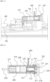
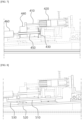
- FIG. 1 is a cross-sectional view illustrating a gas collecting apparatus according of the present disclosure.
- FIG. 2 is an enlarged cross-sectional view of a local region of FIG. 1 .
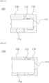
- FIGS. 3a and 3b are cross-sectional views illustrating a jig unit 100.
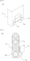
- FIG. 4 is a perspective view illustrating a battery storage unit 710.
- FIG. 5 is a cross-sectional view illustrating a battery storage unit 710.
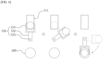
- FIG. 6 is a conceptual diagram illustrating movement of the jig unit 100.
- FIG. 7 is a cross-sectional view illustrating a first driving unit.
- FIG. 8 is a cross-sectional view illustrating a second driving unit 500.
- the gas collecting apparatus of the present disclosure is specialized for collecting gas generated inside the cylindrical battery 11, and may automate most processes for gas collection, such as loading of the battery, perforating of the battery, gas collection, gas delivery, and unloading of the battery.
- the gas collecting apparatus of the present disclosure skips the process of storing the gas generated in the battery in a separate collection container and directly delivers it to the gas analysis unit, it may be capable of real-time analysis as well as preventing phenomena such as deterioration, leakage, and phase change of gas.
- gas collecting apparatus of the present disclosure provides almost the same gas diffusion space for the cylindrical battery 11 of various specifications, it may be advantageous for quantitative analysis.
- the cylindrical battery 11, which is a gas collection target of the gas collecting apparatus of the present disclosure, may accommodate an electrode assembly inside a cylindrical housing made of a rigid material.
- the gas collecting apparatus of the present disclosure may extract gas from the cylindrical battery 11 with an automated system and deliver to the gas analysis unit.
- the gas analysis unit which is to be a gas delivery target may be, for example, a GC-MS device.
- the gas collecting apparatus of the present disclosure may include
- the chamber body unit 310 when a longitudinal direction of the cylindrical battery 11 is referred to as a first direction, the chamber body unit 310 may extend in the first direction, the opening 311 may be formed at the one end of the chamber body unit 310 in the first direction, and the boat unit 200 may move linearly in the first direction by the first driving unit.
- the chamber body unit 310 may be provided in a cylindrical shape with the first direction as a central axis.
- the first direction may be perpendicular to the direction of gravity or a direction forming an acute angle with the direction of gravity.
- one end of the chamber body unit 310 where the opening 311 is formed may be located at a higher location than the other end with respect to the direction of gravity.
- the perforated end is formed higher than the non-perforated end, so that the chamber cap unit 320 and the punching needle 321 located in the chamber cap unit 320 are prevented from being contaminated with the electrolyte.
- the first direction is formed to be inclined with respect to the direction of gravity (not perpendicular to the direction of gravity), so that even if the electrolyte leaks from the cylindrical battery 11, the leaked electrolyte is stored in the electrolyte storage groove 112 of the jig unit 100 to be described later, and the leaked electrolyte can be removed from the apparatus together when the jig unit 100 is unloaded.
- the boat unit 200 may be made of a chemical resistant insulating material.
- the inner space of the chamber body unit 310 may also be provided in a cylindrical shape with the first direction as a central axis.
- the opening 311 may be formed in a circular shape, and the center of the opening 311 and the central axis of the inner space of the chamber body unit 310 may coincide.
- the outer circumferential surface of the chamber body unit 310 at one end side of the chamber body unit 310 may be formed in a tapered shape in which the outer diameter decreases as it approaches one end of the chamber body unit 310.
- a ring-shaped groove 318 into which a sealing member 317 such as an O-ring can be inserted may be formed in a region provided in a tapered shape among the outer circumferential surface of the chamber body unit 310.
- a punching needle 321 may be provided on the one side of the chamber cap unit 320 at a location facing the cylindrical battery 11, and the first driving unit may move the boat unit 200 toward the chamber cap unit 320 side to form a perforated hole in the cylindrical battery 11 by the punching needle 321.
- the chamber cap unit 320 may be provided in a disk shape.
- the punching needle 321 may be located at the center of the chamber cap unit 320, and the center of the chamber cap unit 320 and the center of the opening 311 may be located on a straight line coincident with the central axis of the cylindrical space formed inside the chamber body unit 310.
- a cylindrical sealing frame 322 into which one end of the chamber body unit 310 can be inserted may be formed on one side of the chamber cap unit 320.
- the inner circumferential surface of the sealing frame 322 may be provided in a tapered shape in which the inner diameter increases as it approaches the chamber body unit 310.
- the sealing frame 322 may cover the tapered region of the outer circumferential surface of the chamber body unit 310 when the chamber cap unit 320 and the chamber body unit 310 are coupled.
- the jig unit 100 may be provided in a cylindrical shape extending in the first direction, the cylindrical battery 11 may be mounted in the jig unit 100 so that an outer circumferential surface of the cylindrical battery 11 is in close contact with an inner circumferential surface of the jig unit 100, and a needle insertion hole 111 may be formed at one end in the first direction of the jig unit 100.
- the needle insertion hole 111 may also be located on a straight line where the center of the chamber cap unit 320 and the center of the opening 311 are located.
- the jig unit 100 may include a first jig 110 covering one end of the cylindrical battery 11 and a second jig 120 covering the other end of the cylindrical battery 11.
- the jig unit 100 may be formed of two jigs respectively inserted into both ends of the cylindrical battery 11.
- An electrolyte storage groove 112 may be formed on the inner circumferential surface of the jig unit 100, and the electrolyte storage groove 112 may be located adjacent to a side wall where the needle insertion hole 111 is located in an inner space of the jig unit 100.
- the electrolyte storage groove 112 may be formed in a ring shape along the inner circumferential surface of the jig unit 100.
- the width and depth of the electrolyte storage groove 112 may be determined in consideration of electrolyte injected into the cylindrical battery 11 mounted in the jig unit 100.
- the depth of the electrolyte storage groove 112 may be formed to be 10% to 30% of the outer diameter of the cylindrical battery 11. More preferably, the depth of the electrolyte storage groove 112 may be formed to be 15% to 25% of the outer diameter of the cylindrical battery 11. For example, the depth of the electrolyte storage groove 112 may be formed to be 20% of the outer diameter of the cylindrical battery 11.
- a plurality of the jig units 100 may be provided, and one cylindrical battery 11 may be mounted in each of the plurality of jig units 100.
- the gas collecting apparatus of the present disclosure may sequentially collect gas with an automated system for a plurality of cylindrical batteries 11, and at this time, the jig unit 100 may be individually assigned to each cylindrical battery 11.
- the gas collecting apparatus of the present disclosure may further include a battery storage unit 710 in which the plurality of jig units 100 are accommodated; and a battery delivery unit 720 configured to sequentially deliver the plurality of jig units from the battery storage unit to the boat unit 200 one by one.
- a first cylindrical battery 11a may be mounted in a part of the plurality of jig units 100 and a second cylindrical battery 11b may be mounted in another part of the plurality of jig units 100, and the first cylindrical battery 11a and the second cylindrical battery 1 1b are formed with different outer diameters and the plurality of jig units 100 may be all provided with the same outer diameter.
- the gas collecting apparatus of the present disclosure may include various types of jig units 100 having inner spaces corresponding to cylindrical batteries 11 of various specifications, and by having a plurality of jig units 100 having different shapes and sizes of inner spaces have the same external shape, the entire gas collecting process can be equally applied to cylindrical batteries 11 of various specifications.
- the battery storage unit 710 may include a battery storage track 711 in which the plurality of jig units 100 are stored in an aligned state, a battery discharge hole 712 formed at one end of the battery storage track 711 to discharge the plurality of jig units 100 one by one, and an elastic door 713 mounted on an edge of an inlet of the battery discharge hole 712 to prevent the plurality of jig units 100 from being separated from the battery storage unit 710 with a restoring force.
- the boat unit 200 moves between an outer space of the chamber body unit 310 and the battery accommodating space 312 by the first driving unit, wherein the inlet of the battery discharge hole 712 may be provided at a location spaced apart from the boat unit 200 by a predetermined distance so as to face the boat unit 200 in a state of being located in the outer space of the chamber body unit 310.
- the boat unit 200 and the battery discharge hole 712 may be disposed at locations spaced apart from each other by a predetermined distance in a second direction perpendicular to the first direction.
- the battery delivery unit 720 may include a gripper 721 configured to grip one jig unit 100 exposed to the battery discharge hole 712 among the plurality of jig units 100, a rotating member 722 having one end to which the gripper 721 is mounted and extending in a second direction perpendicular to the first direction, and a shaft member 723 which is located between the battery discharge hole 712 and the boat unit 200 in the state of being located in the outer space of the chamber body unit 310 and extends in the first direction, wherein the shaft member 723 may be coupled with the rotating member 722, and the rotating member 722 may rotate with respect to the shaft member 723 serving as a rotation shaft.
- the gripper 721 applies a force greater than the restoring force by which the elastic door 713 fixes the jig unit 100 to the jig unit 100 to take the jig unit 100 out of the battery storage track 711, and the jig unit 100 may be seated on the boat unit 200 while the shaft member 723 continues to rotate.
- the first driving unit may include a power transmission bar 410 extending in the first direction and penetrating the other end of the chamber body unit 310 in the first direction to have one end inserted inside the chamber body unit 310, a moving member 420, the boat unit 200 being coupled to one side of the moving member 420 and the one end of the power transmission bar 410 being coupled to the other side of the moving member 420, a first fixing frame 430 to which the chamber body unit 310 is fixed, a first moving frame 440 to which the power transmission bar 410 is fixed and linearly moving in the first direction based on the first fixing frame 430, a shaft 450 screwed with the first moving frame 440 and coupled to the first fixing frame 430 to be capable of idling, and an electric motor 460 configured to rotate the first shaft 450.
- a power transmission bar 410 extending in the first direction and penetrating the other end of the chamber body unit 310 in the first direction to have one end inserted inside the chamber body unit 310
- a moving member 420
- the first driving unit is provided in a structure that converts the rotational force of the electric motor 460 into linear motion, so that the distance between the cylindrical battery 11 and the punching needle 321 can be precisely controlled.
- an encoder is mounted on the electric motor 460, and the measured distance between the cylindrical battery 11 and the punching needle 321 can be input as a signal of the encoder to the controller that controls the first driving unit.
- a sealing cover 317 surrounding the power transmission bar 410 may be provided inside the chamber body unit 310, and one end of the sealing cover 317 may be fused to the other side of the moving member 420 and the other end of the sealing cover 317 may be fused to an inner wall of the other end side of the chamber body unit 310.
- the moving member 420 is a chemical-resistant metal material and may be coupled by welding a sealing cover 317 made of a metal material.
- the inner space of the chamber body unit 310 is divided into two spaces around the moving member 420, and a space facing one side of the moving member 420 may be the battery accommodating space 312.
- the sealing cover 317 may be provided in a form of bellows. More specifically, the sealing cover 317 may have a form of bellows made of metal.
- the second driving unit 500 may include a second moving frame 510 to which the first fixing frame 430 is fixed, a second fixing frame 520 to which the chamber cap unit 320 is fixed, and a pneumatic actuator 530 configured to move the second moving frame 510 in the first direction based on the second fixing frame 520.
- the second driving unit 500 may move the entire chamber body unit 310.
- the second driving unit 500 may enhance airtightness by maintaining continuous pressurization during gas collection by coupling the chamber body unit 310 and the chamber cap unit 320 with the power of the pneumatic actuator 530.
- the gas collecting apparatus of the present disclosure may further include an air spraying unit (not shown) located to face the punching needle 321 provided in the chamber cap unit 320 and configured to spray high-pressure gas to the punching needle 321.
- an air spraying unit (not shown) located to face the punching needle 321 provided in the chamber cap unit 320 and configured to spray high-pressure gas to the punching needle 321.
- the second driving unit 500 By the second driving unit 500, the chamber body unit 310 can be completely retracted so as not to be located on an imaginary straight line connecting the punching needle 321 and the nozzle of the air spraying unit.
- the punching needle 321 may be cleaned by spraying high-pressure gas toward the punching needle 321 from a nozzle of the air spraying unit.
- the high-pressure gas sprayed by the air spraying unit may be high-pressure air or an inert gas as a gas for purging.
- the air spraying unit may clean the chamber cap unit 320 contaminated with electrolyte by spraying high-pressure gas to the chamber cap unit 320 for several seconds.
- the gas collecting apparatus of the present disclosure may further include a pressure sensor unit connected to the gas delivery flow path 600, wherein the pressure sensor unit may be configured to measure a pressure of the battery accommodating space 312.
- the gas collecting apparatus of the present disclosure may further include a controller configured to control the first driving unit, wherein the controller may be controlled based on a pressure measured value output from the pressure sensor unit. Specifically, when the pressure measured by the pressure sensor unit is equal to or greater than the set pressure value, the controller may drive the first driving unit to cause the punching needle 321 to retreat from the cylindrical battery 11.
- the set pressure value may be determined in consideration of the type of cylindrical battery 11, charge/discharge state, number of cycles, temperature, and the like.
- the gas collecting apparatus of the present disclosure may further include
- the controller may be configured to control the first valve, the second valve, the third valve, and the fourth valve based on a signal transmitted to the gas analysis unit. Specifically, each valve may be controlled according to a process sequence by receiving information on a gas analysis process.
- Shaft 460...Electric motor, 500...Second driving unit, 510... Second moving frame, 520...Second fixing frame, 530...Pneumatic actuator, 600...Gas delivery flow path, 710...Battery storage unit, 711...Battery storage track, 712...Battery discharge hole, 713...Elastic door, 720...Battery delivery unit, 721...Gripper, 722...Rotating member, 723... Shaft member
- a gas collecting apparatus of the present disclosure may be capable of precise and rapid gas collection by automating the replacement of a jig unit, loading and unloading of a battery, and punching.
- the gas collecting apparatus of the present disclosure may determine whether punching is completed by measuring the movement of the punching needle and the amount of pressure change, thereby preventing accidents such as an internal short circuit of the battery and ensuring safety during gas collection.
Landscapes
- Chemical & Material Sciences (AREA)
- Engineering & Computer Science (AREA)
- Chemical Kinetics & Catalysis (AREA)
- Electrochemistry (AREA)
- General Chemical & Material Sciences (AREA)
- Health & Medical Sciences (AREA)
- Life Sciences & Earth Sciences (AREA)
- Manufacturing & Machinery (AREA)
- Physics & Mathematics (AREA)
- Molecular Biology (AREA)
- Biomedical Technology (AREA)
- Analytical Chemistry (AREA)
- Biochemistry (AREA)
- General Health & Medical Sciences (AREA)
- General Physics & Mathematics (AREA)
- Immunology (AREA)
- Pathology (AREA)
- Battery Mounting, Suspending (AREA)
- Sampling And Sample Adjustment (AREA)
- Gas Exhaust Devices For Batteries (AREA)
- Secondary Cells (AREA)
Applications Claiming Priority (2)
| Application Number | Priority Date | Filing Date | Title |
|---|---|---|---|
| KR1020220121422A KR20240042749A (ko) | 2022-09-26 | 2022-09-26 | 가스 포집 장치 |
| PCT/KR2023/010383 WO2024071614A1 (ko) | 2022-09-26 | 2023-07-19 | 가스 포집 장치 |
Publications (3)
| Publication Number | Publication Date |
|---|---|
| EP4432421A1 true EP4432421A1 (de) | 2024-09-18 |
| EP4432421A4 EP4432421A4 (de) | 2025-01-22 |
| EP4432421B1 EP4432421B1 (de) | 2026-02-18 |
Family
ID=90478266
Family Applications (1)
| Application Number | Title | Priority Date | Filing Date |
|---|---|---|---|
| EP23872739.0A Active EP4432421B1 (de) | 2022-09-26 | 2023-07-19 | Gassammelvorrichtung |
Country Status (6)
| Country | Link |
|---|---|
| US (1) | US20250067635A1 (de) |
| EP (1) | EP4432421B1 (de) |
| JP (1) | JP7749847B2 (de) |
| KR (1) | KR20240042749A (de) |
| CN (1) | CN118435421A (de) |
| WO (1) | WO2024071614A1 (de) |
Family Cites Families (7)
| Publication number | Priority date | Publication date | Assignee | Title |
|---|---|---|---|---|
| KR102268398B1 (ko) * | 2016-10-31 | 2021-06-24 | 주식회사 엘지에너지솔루션 | 이차전지용 가스분석장치 |
| KR102133646B1 (ko) * | 2018-05-21 | 2020-07-13 | 주식회사 엘지화학 | 충방전 겸용 이차전지 발생가스 포집장치 및 포집방법 |
| KR20200004745A (ko) | 2018-07-04 | 2020-01-14 | 주식회사 엘지화학 | 자동화된 이차전지 내부 발생가스 포집장치 및 방법 |
| KR102834731B1 (ko) * | 2019-11-06 | 2025-07-15 | 주식회사 엘지에너지솔루션 | 원통형 전지셀의 가스 분석 장치 및 가스 분석 방법 |
| KR20210125283A (ko) * | 2020-04-08 | 2021-10-18 | (주)이손 | 이차전지 가스 분석 장치 |
| KR102872688B1 (ko) * | 2020-09-22 | 2025-10-21 | 주식회사 엘지에너지솔루션 | 가스 분석 장치 및 방법 |
| KR102439510B1 (ko) | 2021-02-25 | 2022-09-02 | (주)플레이스링크 | 고객 맞춤형 상점 연계할인율 및 상점 추천 시스템 그리고 방법 |
-
2022
- 2022-09-26 KR KR1020220121422A patent/KR20240042749A/ko active Pending
-
2023
- 2023-07-19 WO PCT/KR2023/010383 patent/WO2024071614A1/ko not_active Ceased
- 2023-07-19 JP JP2024536010A patent/JP7749847B2/ja active Active
- 2023-07-19 CN CN202380016225.3A patent/CN118435421A/zh active Pending
- 2023-07-19 EP EP23872739.0A patent/EP4432421B1/de active Active
- 2023-07-19 US US18/723,855 patent/US20250067635A1/en active Pending
Also Published As
| Publication number | Publication date |
|---|---|
| JP7749847B2 (ja) | 2025-10-06 |
| EP4432421A4 (de) | 2025-01-22 |
| EP4432421B1 (de) | 2026-02-18 |
| US20250067635A1 (en) | 2025-02-27 |
| WO2024071614A1 (ko) | 2024-04-04 |
| JP2024546966A (ja) | 2024-12-26 |
| KR20240042749A (ko) | 2024-04-02 |
| CN118435421A (zh) | 2024-08-02 |
Similar Documents
| Publication | Publication Date | Title |
|---|---|---|
| KR102403865B1 (ko) | 가스 포집 장치 및 방법 | |
| EP3809512B1 (de) | Vorrichtung zum sammeln von innengasen einer sekundärbatterie | |
| KR102823069B1 (ko) | 전지 내부가스 포집 장치 | |
| KR102397315B1 (ko) | 이차전지 내부가스 포집 장치 | |
| EP4397953B1 (de) | Gassammelvorrichtung | |
| KR102732786B1 (ko) | 가스 포집 장치 | |
| EP4432421B1 (de) | Gassammelvorrichtung | |
| EP4414683B1 (de) | Gassammelvorrichtung | |
| US20250327827A1 (en) | Gas analysis device | |
| KR102835646B1 (ko) | 가스 포집 장치 | |
| KR102823083B1 (ko) | 가스 분석 장치 | |
| EP4650747A1 (de) | Gassammelvorrichtung und gasanalysevorrichtung damit | |
| KR20250109882A (ko) | 가스 포집 장치 | |
| KR20250030121A (ko) | 가스 포집 장치 |
Legal Events
| Date | Code | Title | Description |
|---|---|---|---|
| STAA | Information on the status of an ep patent application or granted ep patent |
Free format text: STATUS: THE INTERNATIONAL PUBLICATION HAS BEEN MADE |
|
| PUAI | Public reference made under article 153(3) epc to a published international application that has entered the european phase |
Free format text: ORIGINAL CODE: 0009012 |
|
| STAA | Information on the status of an ep patent application or granted ep patent |
Free format text: STATUS: REQUEST FOR EXAMINATION WAS MADE |
|
| 17P | Request for examination filed |
Effective date: 20240612 |
|
| AK | Designated contracting states |
Kind code of ref document: A1 Designated state(s): AL AT BE BG CH CY CZ DE DK EE ES FI FR GB GR HR HU IE IS IT LI LT LU LV MC ME MK MT NL NO PL PT RO RS SE SI SK SM TR |
|
| A4 | Supplementary search report drawn up and despatched |
Effective date: 20250103 |
|
| RIC1 | Information provided on ipc code assigned before grant |
Ipc: G01N 1/22 20060101ALI20241219BHEP Ipc: H01M 10/42 20060101AFI20241219BHEP |
|
| GRAP | Despatch of communication of intention to grant a patent |
Free format text: ORIGINAL CODE: EPIDOSNIGR1 |
|
| STAA | Information on the status of an ep patent application or granted ep patent |
Free format text: STATUS: GRANT OF PATENT IS INTENDED |
|
| DAV | Request for validation of the european patent (deleted) | ||
| DAX | Request for extension of the european patent (deleted) | ||
| INTG | Intention to grant announced |
Effective date: 20251009 |
|
| P01 | Opt-out of the competence of the unified patent court (upc) registered |
Free format text: CASE NUMBER: UPC_APP_0011437_4432421/2025 Effective date: 20251029 |
|
| GRAS | Grant fee paid |
Free format text: ORIGINAL CODE: EPIDOSNIGR3 |
|
| GRAA | (expected) grant |
Free format text: ORIGINAL CODE: 0009210 |
|
| STAA | Information on the status of an ep patent application or granted ep patent |
Free format text: STATUS: THE PATENT HAS BEEN GRANTED |
|
| AK | Designated contracting states |
Kind code of ref document: B1 Designated state(s): AL AT BE BG CH CY CZ DE DK EE ES FI FR GB GR HR HU IE IS IT LI LT LU LV MC ME MK MT NL NO PL PT RO RS SE SI SK SM TR |
|
| REG | Reference to a national code |
Ref country code: CH Ref legal event code: F10 Free format text: ST27 STATUS EVENT CODE: U-0-0-F10-F00 (AS PROVIDED BY THE NATIONAL OFFICE) Effective date: 20260218 Ref country code: GB Ref legal event code: FG4D |
|
| REG | Reference to a national code |
Ref country code: IE Ref legal event code: FG4D |
|
| REG | Reference to a national code |
Ref country code: DE Ref legal event code: R096 Ref document number: 602023012368 Country of ref document: DE |