EP4432433A1 - Zylindrische batterie - Google Patents
Zylindrische batterie Download PDFInfo
- Publication number
- EP4432433A1 EP4432433A1 EP22892530.1A EP22892530A EP4432433A1 EP 4432433 A1 EP4432433 A1 EP 4432433A1 EP 22892530 A EP22892530 A EP 22892530A EP 4432433 A1 EP4432433 A1 EP 4432433A1
- Authority
- EP
- European Patent Office
- Prior art keywords
- bottom portion
- cylindrical battery
- electrode assembly
- negative electrode
- gasket
- Prior art date
- Legal status (The legal status is an assumption and is not a legal conclusion. Google has not performed a legal analysis and makes no representation as to the accuracy of the status listed.)
- Pending
Links
- 238000007789 sealing Methods 0.000 claims abstract description 29
- 230000008878 coupling Effects 0.000 abstract 1
- 238000010168 coupling process Methods 0.000 abstract 1
- 238000005859 coupling reaction Methods 0.000 abstract 1
- 230000002093 peripheral effect Effects 0.000 abstract 1
- 239000000203 mixture Substances 0.000 description 16
- 238000004804 winding Methods 0.000 description 16
- 239000010410 layer Substances 0.000 description 12
- -1 polytetrafluoroethylene Polymers 0.000 description 12
- 229910052751 metal Inorganic materials 0.000 description 10
- 239000002184 metal Substances 0.000 description 9
- OKTJSMMVPCPJKN-UHFFFAOYSA-N Carbon Chemical group [C] OKTJSMMVPCPJKN-UHFFFAOYSA-N 0.000 description 8
- 239000011230 binding agent Substances 0.000 description 8
- 239000011255 nonaqueous electrolyte Substances 0.000 description 8
- 239000007773 negative electrode material Substances 0.000 description 7
- 230000035939 shock Effects 0.000 description 7
- 239000010408 film Substances 0.000 description 6
- 239000000463 material Substances 0.000 description 6
- WHXSMMKQMYFTQS-UHFFFAOYSA-N Lithium Chemical compound [Li] WHXSMMKQMYFTQS-UHFFFAOYSA-N 0.000 description 5
- 229910052782 aluminium Inorganic materials 0.000 description 5
- 239000003792 electrolyte Substances 0.000 description 5
- 229910002804 graphite Inorganic materials 0.000 description 5
- 239000010439 graphite Substances 0.000 description 5
- 229910052744 lithium Inorganic materials 0.000 description 5
- 229920005672 polyolefin resin Polymers 0.000 description 5
- 239000007774 positive electrode material Substances 0.000 description 5
- 229920005989 resin Polymers 0.000 description 5
- 239000011347 resin Substances 0.000 description 5
- 150000003839 salts Chemical class 0.000 description 5
- 239000003125 aqueous solvent Substances 0.000 description 4
- 239000011248 coating agent Substances 0.000 description 4
- 238000000576 coating method Methods 0.000 description 4
- 239000006258 conductive agent Substances 0.000 description 4
- 238000004519 manufacturing process Methods 0.000 description 4
- 229920001343 polytetrafluoroethylene Polymers 0.000 description 4
- 239000004810 polytetrafluoroethylene Substances 0.000 description 4
- 229920002981 polyvinylidene fluoride Polymers 0.000 description 4
- 238000003466 welding Methods 0.000 description 4
- 229920002134 Carboxymethyl cellulose Polymers 0.000 description 3
- 239000004698 Polyethylene Substances 0.000 description 3
- 239000004743 Polypropylene Substances 0.000 description 3
- XAGFODPZIPBFFR-UHFFFAOYSA-N aluminium Chemical compound [Al] XAGFODPZIPBFFR-UHFFFAOYSA-N 0.000 description 3
- 239000003575 carbonaceous material Substances 0.000 description 3
- 239000008151 electrolyte solution Substances 0.000 description 3
- 239000011888 foil Substances 0.000 description 3
- 239000002905 metal composite material Substances 0.000 description 3
- 229920002239 polyacrylonitrile Polymers 0.000 description 3
- 229920000573 polyethylene Polymers 0.000 description 3
- 229920001155 polypropylene Polymers 0.000 description 3
- 229920000178 Acrylic resin Polymers 0.000 description 2
- 239000004925 Acrylic resin Substances 0.000 description 2
- RYGMFSIKBFXOCR-UHFFFAOYSA-N Copper Chemical compound [Cu] RYGMFSIKBFXOCR-UHFFFAOYSA-N 0.000 description 2
- OIFBSDVPJOWBCH-UHFFFAOYSA-N Diethyl carbonate Chemical compound CCOC(=O)OCC OIFBSDVPJOWBCH-UHFFFAOYSA-N 0.000 description 2
- KMTRUDSVKNLOMY-UHFFFAOYSA-N Ethylene carbonate Chemical compound O=C1OCCO1 KMTRUDSVKNLOMY-UHFFFAOYSA-N 0.000 description 2
- YCKRFDGAMUMZLT-UHFFFAOYSA-N Fluorine atom Chemical compound [F] YCKRFDGAMUMZLT-UHFFFAOYSA-N 0.000 description 2
- 229910001290 LiPF6 Inorganic materials 0.000 description 2
- HBBGRARXTFLTSG-UHFFFAOYSA-N Lithium ion Chemical compound [Li+] HBBGRARXTFLTSG-UHFFFAOYSA-N 0.000 description 2
- 239000002033 PVDF binder Substances 0.000 description 2
- 229920003171 Poly (ethylene oxide) Polymers 0.000 description 2
- 239000006230 acetylene black Substances 0.000 description 2
- 229910021383 artificial graphite Inorganic materials 0.000 description 2
- QHIWVLPBUQWDMQ-UHFFFAOYSA-N butyl prop-2-enoate;methyl 2-methylprop-2-enoate;prop-2-enoic acid Chemical compound OC(=O)C=C.COC(=O)C(C)=C.CCCCOC(=O)C=C QHIWVLPBUQWDMQ-UHFFFAOYSA-N 0.000 description 2
- 239000001768 carboxy methyl cellulose Substances 0.000 description 2
- 235000010948 carboxy methyl cellulose Nutrition 0.000 description 2
- 239000008112 carboxymethyl-cellulose Substances 0.000 description 2
- 229920002678 cellulose Polymers 0.000 description 2
- 239000001913 cellulose Substances 0.000 description 2
- 229910052802 copper Inorganic materials 0.000 description 2
- 239000010949 copper Substances 0.000 description 2
- 238000006073 displacement reaction Methods 0.000 description 2
- 238000001035 drying Methods 0.000 description 2
- JBTWLSYIZRCDFO-UHFFFAOYSA-N ethyl methyl carbonate Chemical compound CCOC(=O)OC JBTWLSYIZRCDFO-UHFFFAOYSA-N 0.000 description 2
- 229910052731 fluorine Inorganic materials 0.000 description 2
- 239000011737 fluorine Substances 0.000 description 2
- NBVXSUQYWXRMNV-UHFFFAOYSA-N fluoromethane Chemical compound FC NBVXSUQYWXRMNV-UHFFFAOYSA-N 0.000 description 2
- 239000007789 gas Substances 0.000 description 2
- 229910001416 lithium ion Inorganic materials 0.000 description 2
- 229910052748 manganese Inorganic materials 0.000 description 2
- 239000012046 mixed solvent Substances 0.000 description 2
- 230000004048 modification Effects 0.000 description 2
- 238000012986 modification Methods 0.000 description 2
- 229910052759 nickel Inorganic materials 0.000 description 2
- 229920011301 perfluoro alkoxyl alkane Polymers 0.000 description 2
- 229920001721 polyimide Polymers 0.000 description 2
- 239000009719 polyimide resin Substances 0.000 description 2
- 238000003825 pressing Methods 0.000 description 2
- 239000002002 slurry Substances 0.000 description 2
- 238000009987 spinning Methods 0.000 description 2
- 229920003048 styrene butadiene rubber Polymers 0.000 description 2
- 239000002344 surface layer Substances 0.000 description 2
- 229910000838 Al alloy Inorganic materials 0.000 description 1
- 229910000881 Cu alloy Inorganic materials 0.000 description 1
- 229910002995 LiNi0.8Co0.15Al0.05O2 Inorganic materials 0.000 description 1
- 229910018484 Ni—Cu—Ni Inorganic materials 0.000 description 1
- 239000004372 Polyvinyl alcohol Substances 0.000 description 1
- XUIMIQQOPSSXEZ-UHFFFAOYSA-N Silicon Chemical compound [Si] XUIMIQQOPSSXEZ-UHFFFAOYSA-N 0.000 description 1
- 229920002125 Sokalan® Polymers 0.000 description 1
- 229910000831 Steel Inorganic materials 0.000 description 1
- 239000002174 Styrene-butadiene Substances 0.000 description 1
- 230000002159 abnormal effect Effects 0.000 description 1
- 229910045601 alloy Inorganic materials 0.000 description 1
- 239000000956 alloy Substances 0.000 description 1
- 150000001408 amides Chemical class 0.000 description 1
- 238000005452 bending Methods 0.000 description 1
- 230000008901 benefit Effects 0.000 description 1
- 229910052796 boron Inorganic materials 0.000 description 1
- 229910052799 carbon Inorganic materials 0.000 description 1
- 229910052804 chromium Inorganic materials 0.000 description 1
- 238000005253 cladding Methods 0.000 description 1
- 239000002131 composite material Substances 0.000 description 1
- 150000001875 compounds Chemical class 0.000 description 1
- 239000011889 copper foil Substances 0.000 description 1
- 238000005520 cutting process Methods 0.000 description 1
- 238000010586 diagram Methods 0.000 description 1
- 239000002003 electrode paste Substances 0.000 description 1
- 150000002148 esters Chemical class 0.000 description 1
- 150000002170 ethers Chemical class 0.000 description 1
- 229910021469 graphitizable carbon Inorganic materials 0.000 description 1
- 125000005843 halogen group Chemical group 0.000 description 1
- 230000020169 heat generation Effects 0.000 description 1
- 125000004435 hydrogen atom Chemical group [H]* 0.000 description 1
- 229910052738 indium Inorganic materials 0.000 description 1
- 239000011810 insulating material Substances 0.000 description 1
- 238000009413 insulation Methods 0.000 description 1
- 230000010220 ion permeability Effects 0.000 description 1
- 229910052742 iron Inorganic materials 0.000 description 1
- 239000003273 ketjen black Substances 0.000 description 1
- 239000007788 liquid Substances 0.000 description 1
- 239000011244 liquid electrolyte Substances 0.000 description 1
- 229910003002 lithium salt Inorganic materials 0.000 description 1
- 159000000002 lithium salts Chemical class 0.000 description 1
- 229910052749 magnesium Inorganic materials 0.000 description 1
- 239000011325 microbead Substances 0.000 description 1
- 229910021382 natural graphite Inorganic materials 0.000 description 1
- 229910052758 niobium Inorganic materials 0.000 description 1
- 150000002825 nitriles Chemical class 0.000 description 1
- 239000004745 nonwoven fabric Substances 0.000 description 1
- 229920000642 polymer Polymers 0.000 description 1
- 229920002451 polyvinyl alcohol Polymers 0.000 description 1
- 238000001556 precipitation Methods 0.000 description 1
- 238000002360 preparation method Methods 0.000 description 1
- 229910052710 silicon Inorganic materials 0.000 description 1
- 239000010703 silicon Substances 0.000 description 1
- 239000002356 single layer Substances 0.000 description 1
- 239000007784 solid electrolyte Substances 0.000 description 1
- 239000002904 solvent Substances 0.000 description 1
- 239000010959 steel Substances 0.000 description 1
- 229910052715 tantalum Inorganic materials 0.000 description 1
- 239000002562 thickening agent Substances 0.000 description 1
- 239000010409 thin film Substances 0.000 description 1
- 229910052718 tin Inorganic materials 0.000 description 1
- 229910052719 titanium Inorganic materials 0.000 description 1
- 229910052721 tungsten Inorganic materials 0.000 description 1
- 229910052720 vanadium Inorganic materials 0.000 description 1
- XLYOFNOQVPJJNP-UHFFFAOYSA-N water Substances O XLYOFNOQVPJJNP-UHFFFAOYSA-N 0.000 description 1
- 239000002759 woven fabric Substances 0.000 description 1
- 229910052725 zinc Inorganic materials 0.000 description 1
- 229910052726 zirconium Inorganic materials 0.000 description 1
Images



Classifications
-
- H—ELECTRICITY
- H01—ELECTRIC ELEMENTS
- H01M—PROCESSES OR MEANS, e.g. BATTERIES, FOR THE DIRECT CONVERSION OF CHEMICAL ENERGY INTO ELECTRICAL ENERGY
- H01M10/00—Secondary cells; Manufacture thereof
- H01M10/04—Construction or manufacture in general
- H01M10/0422—Cells or battery with cylindrical casing
-
- H—ELECTRICITY
- H01—ELECTRIC ELEMENTS
- H01M—PROCESSES OR MEANS, e.g. BATTERIES, FOR THE DIRECT CONVERSION OF CHEMICAL ENERGY INTO ELECTRICAL ENERGY
- H01M10/00—Secondary cells; Manufacture thereof
- H01M10/04—Construction or manufacture in general
- H01M10/0431—Cells with wound or folded electrodes
-
- H—ELECTRICITY
- H01—ELECTRIC ELEMENTS
- H01M—PROCESSES OR MEANS, e.g. BATTERIES, FOR THE DIRECT CONVERSION OF CHEMICAL ENERGY INTO ELECTRICAL ENERGY
- H01M50/00—Constructional details or processes of manufacture of the non-active parts of electrochemical cells other than fuel cells, e.g. hybrid cells
- H01M50/10—Primary casings; Jackets or wrappings
- H01M50/147—Lids or covers
- H01M50/148—Lids or covers characterised by their shape
- H01M50/152—Lids or covers characterised by their shape for cells having curved cross-section, e.g. round or elliptic
-
- H—ELECTRICITY
- H01—ELECTRIC ELEMENTS
- H01M—PROCESSES OR MEANS, e.g. BATTERIES, FOR THE DIRECT CONVERSION OF CHEMICAL ENERGY INTO ELECTRICAL ENERGY
- H01M50/00—Constructional details or processes of manufacture of the non-active parts of electrochemical cells other than fuel cells, e.g. hybrid cells
- H01M50/10—Primary casings; Jackets or wrappings
- H01M50/147—Lids or covers
- H01M50/166—Lids or covers characterised by the methods of assembling casings with lids
- H01M50/167—Lids or covers characterised by the methods of assembling casings with lids by crimping
-
- H—ELECTRICITY
- H01—ELECTRIC ELEMENTS
- H01M—PROCESSES OR MEANS, e.g. BATTERIES, FOR THE DIRECT CONVERSION OF CHEMICAL ENERGY INTO ELECTRICAL ENERGY
- H01M50/00—Constructional details or processes of manufacture of the non-active parts of electrochemical cells other than fuel cells, e.g. hybrid cells
- H01M50/10—Primary casings; Jackets or wrappings
- H01M50/183—Sealing members
- H01M50/184—Sealing members characterised by their shape or structure
-
- H—ELECTRICITY
- H01—ELECTRIC ELEMENTS
- H01M—PROCESSES OR MEANS, e.g. BATTERIES, FOR THE DIRECT CONVERSION OF CHEMICAL ENERGY INTO ELECTRICAL ENERGY
- H01M50/00—Constructional details or processes of manufacture of the non-active parts of electrochemical cells other than fuel cells, e.g. hybrid cells
- H01M50/10—Primary casings; Jackets or wrappings
- H01M50/183—Sealing members
- H01M50/186—Sealing members characterised by the disposition of the sealing members
-
- H—ELECTRICITY
- H01—ELECTRIC ELEMENTS
- H01M—PROCESSES OR MEANS, e.g. BATTERIES, FOR THE DIRECT CONVERSION OF CHEMICAL ENERGY INTO ELECTRICAL ENERGY
- H01M50/00—Constructional details or processes of manufacture of the non-active parts of electrochemical cells other than fuel cells, e.g. hybrid cells
- H01M50/50—Current conducting connections for cells or batteries
- H01M50/543—Terminals
- H01M50/552—Terminals characterised by their shape
- H01M50/559—Terminals adapted for cells having curved cross-section, e.g. round, elliptic or button cells
- H01M50/56—Cup shaped terminals
-
- Y—GENERAL TAGGING OF NEW TECHNOLOGICAL DEVELOPMENTS; GENERAL TAGGING OF CROSS-SECTIONAL TECHNOLOGIES SPANNING OVER SEVERAL SECTIONS OF THE IPC; TECHNICAL SUBJECTS COVERED BY FORMER USPC CROSS-REFERENCE ART COLLECTIONS [XRACs] AND DIGESTS
- Y02—TECHNOLOGIES OR APPLICATIONS FOR MITIGATION OR ADAPTATION AGAINST CLIMATE CHANGE
- Y02E—REDUCTION OF GREENHOUSE GAS [GHG] EMISSIONS, RELATED TO ENERGY GENERATION, TRANSMISSION OR DISTRIBUTION
- Y02E60/00—Enabling technologies; Technologies with a potential or indirect contribution to GHG emissions mitigation
- Y02E60/10—Energy storage using batteries
Definitions
- the present disclosure generally relates to a cylindrical battery.
- a cylindrical battery is generally required to have resistance to vibration and shock, and particularly in the case where a cylindrical battery is mounted on a vehicle, the cylindrical battery may be required to meet severe requirements for resistance to vibration and shock.
- PATENT LITERATURE 1 discloses a cylindrical battery in which an annular bottom portion extending in a radial direction in a gasket is brought into contact with an electrode assembly. In this cylindrical battery, when the annular bottom portion appropriately presses on the electrode assembly in an axial direction, the electrode assembly is restrained in the axial direction by the gasket, which makes it difficult to move the electrode assembly in the axial direction. Therefore, this can easily increase the resistance to vibration and shock.
- PATENT LITERATURE 1 Japanese Utility Model Application Publication No. Hei02-049064
- the electrode assembly is pressed by the annular bottom portion of the gasket extending in the radial direction. Accordingly, since a force received by the electrode assembly from the bottom portion greatly changes depending on an axial position of the annular bottom portion, it becomes necessary to perform highly accurate positioning of the annular bottom portion in the axial direction. However, since it is difficult to perform highly accurate positioning of the annular bottom portion in the axial direction, and in addition, dimensional variation of the electrode assembly or the like occurs, it is difficult to press the gasket on the electrode assembly with an appropriate force.
- a cylindrical battery according to the present disclosure comprises an electrode assembly in which a positive electrode and a negative electrode are wound with a separator interposed between the positive electrode and the negative electrode, a bottomed cylindrical exterior housing can that houses the electrode assembly, a sealing assembly with which an opening of the exterior housing can is capped, and a gasket that insulates the sealing assembly from the exterior housing can, wherein the gasket has an annular portion that contacts a bottom surface of the sealing assembly, a bottom portion that is located on a side closer to the electrode assembly than the annular portion and presses on the electrode assembly, and a connecting portion that connects between the annular portion and the bottom portion and is inclined toward a radial center while approaching the bottom portion, and the bottom portion has a first through hole that is located to include the radial center and a plurality of second through holes that are located on an outer circumferential portion.
- an electrode assembly can be easily pressed in an axial direction by a gasket with an appropriate force, and the resistance of the cylindrical battery to vibration and shock can be improved.
- the cylindrical battery of the present disclosure may be a primary battery, or may be a secondary battery. Additionally, the cylindrical battery may be a battery using an aqueous electrolyte, or may be a battery using a non-aqueous electrolyte.
- a non-aqueous electrolyte secondary battery (lithium ion battery) using a non-aqueous electrolyte will be exemplified as a cylindrical battery 10 of an embodiment, but the cylindrical battery of the present disclosure is not limited to this.
- FIG. 1 is an axial sectional view of the cylindrical battery 10 according to an embodiment of the present disclosure
- FIG. 2 is a perspective view of an electrode assembly 14 of the cylindrical battery 10.
- the cylindrical battery 10 comprises a wound-type electrode assembly 14, a non-aqueous electrolyte (not illustrated), and a bottomed cylindrical metal exterior housing can 16 that houses the electrode assembly 14 and the non-aqueous electrolyte, and a sealing assembly 17 with which an opening of the exterior housing can 16 is capped.
- the electrode assembly 14 has a wound structure in which an elongated positive electrode 11 and an elongated negative electrode 12 are wound with two elongated separators 13 each interposed between the positive electrode 11 and the negative electrode 12.
- the negative electrode 12 is formed to be one size larger than the positive electrode 11 in order to prevent precipitation of lithium. That is, the negative electrode 12 is formed to be longer in the longitudinal direction and the width direction (short direction) than the positive electrode 11.
- the two separators 13 are each formed to be at least one size larger than the positive electrode 11, and are disposed so as to interpose, for example, the positive electrode 11 therebetween.
- the negative electrode 12 may include a winding start end of the electrode assembly 14. However, the separator 13 generally extends beyond a winding start side end of the negative electrode 12, and a winding start side end of the separator 13 serves as the winding start end of the electrode assembly 14.
- the non-aqueous electrolyte includes a non-aqueous solvent, and an electrolyte salt dissolved in the non-aqueous solvent.
- the non-aqueous solvent may include esters, ethers, nitriles, amides, and mixed solvents containing two or more selected from the foregoing.
- the non-aqueous solvent may contain a halogen-substituted product obtained by substituting at least some of hydrogen atoms in these solvents with a halogen atom such as fluorine.
- the non-aqueous electrolyte is not limited to a liquid electrolyte and may be a solid electrolyte that uses a gel polymer or the like.
- the electrolyte salt a lithium salt such as LiPF 6 is used.
- the positive electrode 11 has a positive electrode current collector and a positive electrode mixture layer formed on each surface of the positive electrode current collector.
- the positive electrode current collector may include a foil of metal such as aluminum or an aluminum alloy, which is stable within a potential range of the positive electrode 11, and a film in which such a metal is disposed on a surface layer thereof.
- the positive electrode mixture layer includes a positive electrode active material, a conductive agent, and a binder.
- the positive electrode 11 can be produced by, for example, applying a positive electrode mixture slurry including a positive electrode active material, a conductive agent, a binder, and the like on a positive electrode current collector, drying the resulting coating film, and then compressing the coating film to form a positive electrode mixture layer on each surface of the current collector.
- the positive electrode active material is composed of a lithium-containing metal composite oxide as a main component.
- metal elements contained in the lithium-containing metal composite oxide include Ni, Co, Mn, Al, B, Mg, Ti, V, Cr, Fe, Cu, Zn, Ga, Sr, Zr, Nb, In, Sn, Ta, and W.
- An example of a preferable lithium-containing metal composite oxide is a composite oxide containing at least one of Ni, Co, Mn and Al.
- Examples of the conductive agent included in the positive electrode mixture layer may include carbon materials such as carbon black, acetylene black, Ketjen black, and graphite.
- Examples of the binder included in the positive electrode mixture layer may include fluorocarbon resins such as polytetrafluoroethylene (PTFE) and polyvinylidene fluoride (PVdF), polyacrylonitrile (PAN), polyimide resins, acrylic resins, and polyolefin resins. These resins may be used in combination with cellulose derivatives such as carboxymethyl cellulose (CMC) or a salt thereof, a polyethylene oxide (PEO), or the like.
- CMC carboxymethyl cellulose
- PEO polyethylene oxide
- the negative electrode 12 has a negative electrode current collector and a negative electrode mixture layer formed on each surface of the negative electrode current collector.
- the negative electrode current collector may include a foil of a metal such as copper or a copper alloy, which is stable within a potential range of the negative electrode 12, and a film in which such a metal is disposed on a surface layer thereof.
- the negative electrode mixture layer includes a negative electrode active material, and a binder.
- the negative electrode 12 can be produced by, for example, applying a negative electrode mixture slurry including a negative electrode active material, a binder, and the like on a negative electrode current collector, drying the resulting coating film, and then compressing the coating film to form a negative electrode mixture layer on each surface of the current collector.
- the negative electrode active material a carbon material that reversibly occludes and releases lithium ions is generally used.
- a preferable carbon material is graphite including natural graphite such as flaky graphite, massive graphite, and earthy graphite, and artificial graphite such as massive artificial graphite and graphitized mesophase carbon microbeads.
- a silicon (Si) material containing Si may be included in the negative electrode mixture layer.
- a metal alloyed with lithium other than Si an alloy containing such a metal, a compound containing such a metal, and the like may be used.
- fluorocarbon resins PAN, polyimide resins, acrylic resins, polyolefin resins, and the like may be used as in the case of the positive electrode 11, and a styrene-butadiene rubber (SBR) or a modification thereof is preferably used.
- SBR styrene-butadiene rubber
- CMC CMC or a salt thereof
- PAA polyacrylic acid
- polyvinyl alcohol or the like
- a porous sheet having ion permeability and an insulation property is used as the separator 13.
- the porous sheet include a microporous thin film, a woven fabric, and a nonwoven fabric.
- the material of the separator 13 is preferably a polyolefin resin such as polyethylene or polypropylene, or a cellulose.
- the separator 13 may be either a single layer structure or a laminated structure.
- a heat-resistant layer or the like may be formed on a surface of the separator 13.
- a positive electrode lead 20 is bonded to the positive electrode 11, and a negative electrode lead 21 is bonded on a winding finish-side in the longitudinal direction of the negative electrode 12.
- the cylindrical battery 10 has an upper insulating plate 18 above the electrode assembly 14, and has a lower insulating plate 19 below the electrode assembly 14.
- the positive electrode lead 20 extends toward the sealing assembly 17 through a through hole of the upper insulating plate 18, and the negative electrode lead 21 extends toward a bottom portion 68 of the exterior housing can 16 through the outside of the lower insulating plate 19.
- the positive electrode lead 20 is connected to a lower surface of a bottom plate 23 of the sealing assembly 17, by means of welding or the like.
- a terminal cap 27 constituting a top plate of the sealing assembly 17 is electrically connected to the bottom plate 23, and serves as a positive electrode terminal.
- the negative electrode lead 21 is connected to an inner surface of the bottom portion 68 of the metal exterior housing can 16 by means of welding or the like, and the exterior housing can 16 serves as a negative electrode terminal.
- the positive electrode lead 20 is electrically connected to an intermediate portion such as a center portion in the winding direction of the positive electrode current collector, and the negative electrode lead 21 is electrically connected to a winding finish-side end in the winding direction of the negative electrode current collector.
- the negative electrode lead may be electrically connected to a winding start-side end in the winding direction of the negative electrode current collector.
- the electrode assembly may have two negative electrode leads in which one of the negative electrode leads is electrically connected to the winding start side-end in the winding direction of the negative electrode current collector, and the other negative electrode lead is electrically connected to the winding finish-side end in the winding direction of the negative electrode current collector.
- the winding finish-side end in the winding direction of the negative electrode current collector may be brought into contact with an inner surface of the exterior housing can so that the negative electrode and the exterior housing can are electrically connected to each other.
- the cylindrical battery 10 further comprises a resin gasket 28 disposed between the exterior housing can 16 and the sealing assembly 17.
- the sealing assembly 17 is fixed by caulking to the opening of the exterior housing can 16 with the gasket 28 interposed therebetween. In this way, an internal space of the cylindrical battery 10 is closed.
- the gasket 28 is held between the exterior housing can 16 and the sealing assembly 17, and insulates the sealing assembly 17 from the exterior housing can 16.
- the gasket 28 has a role of a seal material for maintaining the airtightness of the inside of the battery, and a role as an insulating material for insulating the sealing assembly 17 from the exterior housing can 16.
- the exterior housing can 16 houses the electrode assembly 14 and the non-aqueous electrolyte, and has a shoulder 38, a grooved portion 34, a cylindrical portion 30, and a bottom portion 68.
- the grooved portion 34 can be formed by, for example, annularly recessing the one part of the side wall of the exterior housing can 16 toward the radially inward side by a radially inward spinning process.
- the shoulder 38 is formed by bending an upper end of the exterior housing can 16 to the inner side toward a circumferential edge 45 of the sealing assembly 17 when the sealing assembly 17 is fixed by caulking to the exterior housing can 16.
- the sealing assembly 17 is fixed by caulking to the exterior housing can 16 with the gasket 28 interposed between the shoulder 38 and the grooved portion 34.
- the gasket 28 is made of materials having elasticity and electrolyte resistance, which, for example, include polyolefin-based resins such as polyethylene (PE) and polypropylene (PP), or fluorine-based resins such as polytetrafluoroethylene (PTFE) and perfluoroalkoxy alkanes (PFA).
- the gasket 28 has an annular portion 31 that contacts a bottom surface of the sealing assembly 17, a bottom portion 32 that presses on the electrode assembly 14, and a connecting portion 33 that connects between the annular portion 31 and the bottom portion 32.
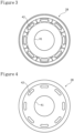
- the bottom portion 32 is located on a side closer to the electrode assembly 14 than the annular portion 31, and has a first through hole 41 that is located to include the radial center and a plurality of second through holes 42 that are located on an outer circumferential portion.
- the plurality of second through holes 42 are arranged along a circumferential direction.
- the connecting portion 33 is inclined toward a center in the radial direction while approaching the bottom portion 32.
- the electrode assembly 14 is directly pressed downward in the axial direction by the gasket 28, thereby suppressing axial movement thereof.
- a shape of the upper insulating plate 18 may be changed so that the gasket 28 presses on the electrode assembly 14 via the upper insulating plate 18.
- the bottom portion 32 is connected to a lower end of the connecting portion 33 that is inclined downward in the axial direction toward a radial center side. Accordingly, the electrode assembly 14 is prevented from receiving excessive pressure from the bottom portion 32 by the elasticity of the connecting portion 33 inclined toward the axial direction. Therefore, the electrode assembly 14 can be easily pressed in the axial direction by the gasket 28 with an appropriate force and the resistance of the cylindrical battery 10 to vibration and shock can be improved.
- the degree of freedom of radial inward displacement of the bottom portion 32 can be increased, and as compared with the case where the first through hole 41 is not provided, the electrode assembly 14 can be easily pressed in the axial direction by the gasket 28 with an appropriate force and in addition, the bottom portion 32 can be prevented from being displaced to become wavy, and the electrode assembly 14 can be efficiently pressed downward.
- the plurality of second through holes 42 are provided on the outer circumferential portion of the bottom portion of the gasket 28.
- the plurality of second through holes 42 are thus provided at a position adjacent to the connecting portion 33, whereby the electrode assembly 14 can be easily pressed in the axial direction by the gasket 28 with an appropriate force.
- the outer circumferential portion of the bottom portion 32 is preferably inclined toward the electrode assembly 14 while approaching the radial center. This can increase the degree of freedom of axial displacement of a portion of the bottom portion 32 by which the electrode assembly 14 is pressed, and therefore, the electrode assembly 14 can be more easily pressed downward with an appropriate force.
- the outer circumferential portion of the bottom portion 32 may be curved toward the electrode assembly 14 while approaching the radial center.
- the thickness of the connecting portion 33 is preferably larger than the thickness of the bottom portion 32, and the inclination angle of the connecting portion 33 with respect to the radial direction is preferably larger than the inclination angle of the outer circumferential portion of the bottom portion 32.
- the sealing assembly 17 has a stacked structure of the bottom plate 23, a lower vent member 24, an insulating member 25, an upper vent member 26, and the terminal cap 27 in this order from the electrode assembly 14 side.
- Each member constituting the sealing assembly 17 has, for example, a disk shape or a ring shape, and each member except for the insulating member 25 is electrically connected to each other.
- the bottom plate 23 has at least one through hole 23a.
- the lower vent member 24 and the upper vent member 26 are connected to each other at respective centers thereof, and the insulating member 25 is interposed between the circumferential edges of the vent members 24 and 26.
- the lower vent member 24 is deformed so as to push the upper vent member 26 upward to the terminal cap 27 side to break, resulting in cutting off of a current path between the lower vent member 24 and the upper vent member 26. If the internal pressure further increases, the upper vent member 26 breaks, and gas is discharged from a through hole 27a in the terminal cap 27. This gas discharge can prevent the cylindrical battery 10 from rupturing due to an excessive increase in internal pressure of the cylindrical battery 10, which makes it possible to improve the safety of the cylindrical battery 10.
- FIG. 3 is a plan view of a single gasket 28 before caulking when seen from an upper side in the axial direction
- FIG. 4 is a plan view of the gasket 28 before caulking when seen from a lower side in the axial direction.
- FIG. 5 is a perspective view illustrating the gasket 28 before caulking so that a cut surface is seen
- FIG. 6 is an axial semi-sectional view of the gasket 28 before caulking.
- each of the first through hole 41 and the plurality of second through holes 42 has the following shape and structure.
- the first through hole 41 is required to be located to include a radial center, but is preferably located at the radial center and has an approximately circular plan shape.
- the plurality of second through holes 42 are arranged at approximately regular intervals in the circumferential direction on the outer circumferential portion of the bottom portion 32, and each second through hole 42 is an elongated hole extending along the circumferential direction.
- An opening area of the first through hole 41 is not limited to a particular value, but for example, is preferably greater than or equal to 10% and less than or equal to 35%, and more preferably greater than or equal to 15% and less than or equal to 25% of an area of an inner diameter portion of the cylindrical portion 30 (see FIG. 1 ).
- the opening area is smaller than 15%, the bottom portion 32 may become wavy, or conversely, when the opening area is larger than 35%, the bottom portion 32 is reduced in area, which may make it difficult to surely press the bottom portion 32 on the electrode assembly 14.
- the opening area of the first through hole is larger than total area of openings of all the second through holes 42.
- the opening area of the first through hole 41 may be smaller than the total area of the openings of all the second through holes 42, and furthermore, the opening area of the first through hole 41 may be smaller than the opening area of the second through hole 42.
- the total area of openings of all the second through holes 42 is, for example, preferably greater than or equal to 5% and less than or equal to 30%, and more preferably greater than or equal to 10% or less than or equal to 20% of the opening area of the first through hole 41.
- the gasket 28 before caulking has a cylindrical portion 60, and the annular portion 31 extends approximately in parallel to the radial direction from a lower end of the cylindrical portion 60.
- the connecting portion 33 is inclined inward in the radial direction and downward in the axial direction from an end on the radially inward side of the annular portion 31 toward the axial direction, and the annular bottom portion 32 extends approximately in parallel to the radial direction from the lower end of the connecting portion 33.
- the thickness of each of the annular portion 31, the connecting portion 33, and the bottom portion 32 is not limited to a particular value. However, as described above, in order to press the bottom portion 32 on the electrode assembly 14 with an appropriate force, as illustrated in FIG.
- the thickness of the annular portion 31 as indicated by an arrow A is preferably larger than the thickness of the connecting portion 33 as indicated by an arrow B
- the thickness of the connecting portion 33 is preferably larger than the thickness of the bottom portion 32 as indicated by an arrow C.
- the thickness of the bottom portion 32 is greater than or equal to 70% and less than or equal to 90% of the thickness of the connecting portion 33, it becomes easy to adjust the pressing force of the bottom portion 32 on the electrode assembly 14 within an appropriate range.
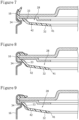
- FIGS. 7 to 9 each are a sectional view explaining deformation of the gasket 28 when caulking is performed.
- a sealing assembly illustrated in each of FIGS. 7 to 9 includes a terminal cap and a bottom plate.
- the connecting portion 33 is deformed downward by a downward force with the upper side of the grooved portion 34 as a fulcrum, and as a result, the bottom portion 32 extending in the radial direction before caulking is deformed to expand to the inside of the battery.
- an inclined portion is formed on the outer circumferential portion of the bottom portion 32.
- the inclination angle of the outer circumferential portion of the bottom portion 32 increases as illustrated in FIGS. 8 and 9 . This can achieve the structure of the gasket 28 after caulking as illustrated in FIG. 1 .
- a gasket having the structure of the gasket 28 after caulking as illustrated in FIG. 1 may be used.
- a positive electrode active material LiNi 0.8 Co 0.15 Al 0.05 O 2 was used as a positive electrode active material. 100 parts by weight of the positive electrode active material, 1.7 parts by weight of poly(vinylidene fluoride) as a binder and 2.5 parts by weight of acetylene black as a conductive agent were mixed to a liquid component to prepare a positive electrode mixture paste. The positive electrode mixture paste was applied to each surface of the positive electrode current collector made of aluminum foil, except for a connection portion of a positive electrode lead, and was dried and then rolled into a predetermined thickness to obtain a positive electrode. The obtained positive electrode was cut into a predetermined size, and the positive electrode lead made of Al was connected to an exposed portion of the current collector by ultrasonic welding.
- a negative electrode active material graphitizable carbon was used. 100 parts by weight of the negative electrode active material, 0.6 parts by weight of poly(vinylidene fluoride) as a binder, 1 part by weight of carboxymethylcellulose as a thickener, and a proper amount of water were stirred by a double-arm kneader to obtain a negative electrode paste.
- the obtained negative electrode mixture paste was applied to each surface of the negative electrode current collector made of copper foil, except for a connection portion of a negative electrode lead, and was dried and then rolled into a predetermined thickness to obtain a negative electrode.
- the negative electrode plate was cut into a predetermined size, and the negative electrode lead made of Ni-Cu-Ni cladding material was connected to an exposed portion of the current collector by ultrasonic welding.
- LiPF 6 lithium hexafluorophosphate
- a thin thickness portion was provided in a circular terminal plate using an aluminum material as a vent member, and a thinnest thickness portion was further formed at a center. Then, a predetermined rupture disc and an insulating plate were connected to produce a sealing assembly.
- the above-described positive electrode and negative electrode were spirally wound with a polyolefin-based resin as the separator interposed therebetween, thereby producing an electrode assembly.
- the electrode assembly was inserted into the exterior housing can produced by drawing a steel plate, and the negative electrode lead was welded to a bottom surface of the exterior housing can and the positive electrode lead was welded to the sealing assembly.
- the above-described spinning was performed on the exterior housing can, and then the exterior housing can was filled with the non-aqueous electrolytic solution.
- the gasket explained using FIGS. 3 to 6 was disposed between the exterior housing can and the sealing assembly, and the caulking explained using FIGS. 7 to 9 was performed in a state in which the electrode assembly was housed in the exterior housing can.
- the cylindrical battery illustrated in FIG. 1 was produced.
- the present disclosure is not limited to the above embodiment and modified examples thereof, and various improvements and changes are possible within the matters described in the claims of the present application and the scope of equivalence of claims.
- the bottom portion 32 of the gasket 28 may be brought into contact with the upper insulating plate 18 to press the upper insulating plate 18 downward.
- the electrode assembly 14 may be pressed downward by the upper insulating plate 18 that has been moved downward by being pressed downward.
- the electrode assembly 14 can be easily pressed in the axial direction with an appropriate force, and the resistance of the electrode assembly 14 to vibration and shock can be easily and securely improved.
Landscapes
- Chemical & Material Sciences (AREA)
- Chemical Kinetics & Catalysis (AREA)
- Electrochemistry (AREA)
- General Chemical & Material Sciences (AREA)
- Engineering & Computer Science (AREA)
- Manufacturing & Machinery (AREA)
- Sealing Battery Cases Or Jackets (AREA)
Applications Claiming Priority (2)
| Application Number | Priority Date | Filing Date | Title |
|---|---|---|---|
| JP2021184257 | 2021-11-11 | ||
| PCT/JP2022/039044 WO2023085030A1 (ja) | 2021-11-11 | 2022-10-20 | 円筒形電池 |
Publications (2)
| Publication Number | Publication Date |
|---|---|
| EP4432433A1 true EP4432433A1 (de) | 2024-09-18 |
| EP4432433A4 EP4432433A4 (de) | 2025-03-19 |
Family
ID=86335637
Family Applications (1)
| Application Number | Title | Priority Date | Filing Date |
|---|---|---|---|
| EP22892530.1A Pending EP4432433A4 (de) | 2021-11-11 | 2022-10-20 | Zylindrische batterie |
Country Status (4)
| Country | Link |
|---|---|
| EP (1) | EP4432433A4 (de) |
| JP (1) | JPWO2023085030A1 (de) |
| CN (1) | CN118541858A (de) |
| WO (1) | WO2023085030A1 (de) |
Families Citing this family (9)
| Publication number | Priority date | Publication date | Assignee | Title |
|---|---|---|---|---|
| CA3239391A1 (en) * | 2022-02-04 | 2023-08-10 | Lg Energy Solution, Ltd. | Battery, battery pack and vehicle including the same |
| CA3242419A1 (en) * | 2022-02-04 | 2023-08-10 | Lg Energy Solution, Ltd. | BATTERY MODULE AND BATTERY BLOCK, AND VEHICLE INCLUDING THEM |
| WO2025094682A1 (ja) * | 2023-10-31 | 2025-05-08 | パナソニックIpマネジメント株式会社 | 密閉型電池 |
| WO2025142268A1 (ja) * | 2023-12-27 | 2025-07-03 | パナソニックIpマネジメント株式会社 | 円筒形電池 |
| KR20250108988A (ko) * | 2024-01-09 | 2025-07-16 | 삼성에스디아이 주식회사 | 배터리 셀 및 배터리 셀 제조방법 |
| EP4621931A1 (de) | 2024-02-02 | 2025-09-24 | Hamedata Technology Co., Limited | Buck-schaltungsanordnung für eine lithiumbatterie und 1,5-v-lithiumbatterie |
| EP4621903A1 (de) | 2024-02-02 | 2025-09-24 | Hamedata Technology Co., Limited | 1.5 v-lithiumbatterie und herstellungsverfahren dafür |
| CN117673498B (zh) | 2024-02-02 | 2024-04-12 | 深圳市华美兴泰科技股份有限公司 | 一种低压锂电池 |
| WO2025161218A1 (zh) | 2024-02-02 | 2025-08-07 | 深圳市华美兴泰科技股份有限公司 | 一种1.5v锂电池及其制造方法 |
Family Cites Families (7)
| Publication number | Priority date | Publication date | Assignee | Title |
|---|---|---|---|---|
| JPH0610624Y2 (ja) | 1988-09-29 | 1994-03-16 | 富士電気化学株式会社 | 筒形非水電解液電池 |
| JPH11260331A (ja) * | 1998-03-05 | 1999-09-24 | Toshiba Battery Co Ltd | 電 池 |
| JP5279341B2 (ja) * | 2008-05-20 | 2013-09-04 | Fdkエナジー株式会社 | 筒形非水電解液電池 |
| KR102007702B1 (ko) * | 2013-01-03 | 2019-10-21 | 삼성에스디아이 주식회사 | 이차 전지 |
| JP2015156307A (ja) * | 2014-02-20 | 2015-08-27 | ソニー株式会社 | 電池ならびに電池パック、電子機器、蓄電装置、電力システムおよび電動車両 |
| KR101947477B1 (ko) * | 2015-07-21 | 2019-02-13 | 주식회사 엘지화학 | 안정성이 향상된 캡 어셈블리 및 이를 포함하는 원형 이차전지 |
| CN113632272A (zh) * | 2019-03-29 | 2021-11-09 | 松下知识产权经营株式会社 | 电池及其制造方法 |
-
2022
- 2022-10-20 JP JP2023559522A patent/JPWO2023085030A1/ja active Pending
- 2022-10-20 WO PCT/JP2022/039044 patent/WO2023085030A1/ja not_active Ceased
- 2022-10-20 CN CN202280072426.0A patent/CN118541858A/zh active Pending
- 2022-10-20 EP EP22892530.1A patent/EP4432433A4/de active Pending
Also Published As
| Publication number | Publication date |
|---|---|
| WO2023085030A1 (ja) | 2023-05-19 |
| JPWO2023085030A1 (de) | 2023-05-19 |
| EP4432433A4 (de) | 2025-03-19 |
| CN118541858A (zh) | 2024-08-23 |
Similar Documents
| Publication | Publication Date | Title |
|---|---|---|
| EP4432433A1 (de) | Zylindrische batterie | |
| JP7799470B2 (ja) | 円筒形電池、及び円筒形電池の製造方法 | |
| JP7709293B2 (ja) | 円筒形電池 | |
| EP3905364B1 (de) | Zylinderförmige batterie | |
| JPWO2018173899A1 (ja) | 非水電解質二次電池 | |
| EP4471927A1 (de) | Zylindrische sekundärbatterie mit nichtwässrigem elektrolyten | |
| US20240178522A1 (en) | Cylindrical battery | |
| EP4318768A1 (de) | Verschlossene batterie | |
| US20240145883A1 (en) | Cylindrical battery and manufacturing method for same | |
| EP4411979A1 (de) | Zylindrische batterie | |
| EP4303974A1 (de) | Zylindrische batterie | |
| EP4300644A1 (de) | Zylindrische batterie | |
| WO2020137716A1 (ja) | 円筒形電池 | |
| US20230079288A1 (en) | Nonaqueous electrolyte secondary battery and electrode for nonaqueous electrolyte secondary batteries | |
| US20220302508A1 (en) | Non-aqueous electrolyte secondary battery and method for producing non-aqueous electrolyte secondary battery | |
| US20250273834A1 (en) | Cylindrical battery | |
| US20250210763A1 (en) | Cylindrical battery | |
| JP7793532B2 (ja) | 円筒形電池 | |
| WO2023176511A1 (ja) | 円筒形電池 | |
| EP4270613A1 (de) | Hermetisch verschlossene batterie | |
| EP4629406A1 (de) | Zylindrische batterie | |
| US20250309422A1 (en) | Cylindrical battery | |
| US20250055159A1 (en) | Cylindrical battery | |
| EP4693639A1 (de) | Zylindrische batterie | |
| EP4597735A1 (de) | Zylindrische batterie |
Legal Events
| Date | Code | Title | Description |
|---|---|---|---|
| STAA | Information on the status of an ep patent application or granted ep patent |
Free format text: STATUS: THE INTERNATIONAL PUBLICATION HAS BEEN MADE |
|
| PUAI | Public reference made under article 153(3) epc to a published international application that has entered the european phase |
Free format text: ORIGINAL CODE: 0009012 |
|
| STAA | Information on the status of an ep patent application or granted ep patent |
Free format text: STATUS: REQUEST FOR EXAMINATION WAS MADE |
|
| 17P | Request for examination filed |
Effective date: 20240425 |
|
| AK | Designated contracting states |
Kind code of ref document: A1 Designated state(s): AL AT BE BG CH CY CZ DE DK EE ES FI FR GB GR HR HU IE IS IT LI LT LU LV MC ME MK MT NL NO PL PT RO RS SE SI SK SM TR |
|
| DAV | Request for validation of the european patent (deleted) | ||
| DAX | Request for extension of the european patent (deleted) | ||
| A4 | Supplementary search report drawn up and despatched |
Effective date: 20250213 |
|
| RIC1 | Information provided on ipc code assigned before grant |
Ipc: H01M 50/167 20210101ALI20250207BHEP Ipc: H01M 10/04 20060101ALI20250207BHEP Ipc: H01M 50/477 20210101ALI20250207BHEP Ipc: H01M 50/474 20210101ALI20250207BHEP Ipc: H01M 50/186 20210101ALI20250207BHEP Ipc: H01M 50/152 20210101ALI20250207BHEP Ipc: H01M 50/14 20210101ALI20250207BHEP Ipc: H01M 50/107 20210101ALI20250207BHEP Ipc: H01M 50/184 20210101AFI20250207BHEP |