EP4432434A1 - Véhicule automobile doté d'une batterie haute tension - Google Patents
Véhicule automobile doté d'une batterie haute tension Download PDFInfo
- Publication number
- EP4432434A1 EP4432434A1 EP23161464.5A EP23161464A EP4432434A1 EP 4432434 A1 EP4432434 A1 EP 4432434A1 EP 23161464 A EP23161464 A EP 23161464A EP 4432434 A1 EP4432434 A1 EP 4432434A1
- Authority
- EP
- European Patent Office
- Prior art keywords
- motor vehicle
- tub
- battery
- vehicle according
- carrier plate
- Prior art date
- Legal status (The legal status is an assumption and is not a legal conclusion. Google has not performed a legal analysis and makes no representation as to the accuracy of the status listed.)
- Pending
Links
- 238000004519 manufacturing process Methods 0.000 claims abstract description 8
- 238000001816 cooling Methods 0.000 claims description 7
- 238000000034 method Methods 0.000 claims description 6
- 101150114468 TUB1 gene Proteins 0.000 description 11
- 239000000853 adhesive Substances 0.000 description 8
- 230000001070 adhesive effect Effects 0.000 description 8
- 238000005304 joining Methods 0.000 description 5
- 238000009434 installation Methods 0.000 description 4
- 239000000463 material Substances 0.000 description 3
- 229910052782 aluminium Inorganic materials 0.000 description 2
- XAGFODPZIPBFFR-UHFFFAOYSA-N aluminium Chemical compound [Al] XAGFODPZIPBFFR-UHFFFAOYSA-N 0.000 description 2
- 238000010276 construction Methods 0.000 description 2
- 238000010924 continuous production Methods 0.000 description 2
- 238000012423 maintenance Methods 0.000 description 2
- 238000003860 storage Methods 0.000 description 2
- 238000005266 casting Methods 0.000 description 1
- 238000005260 corrosion Methods 0.000 description 1
- 230000007797 corrosion Effects 0.000 description 1
- 230000001419 dependent effect Effects 0.000 description 1
- 238000011161 development Methods 0.000 description 1
- 230000018109 developmental process Effects 0.000 description 1
- 238000005516 engineering process Methods 0.000 description 1
- 230000010354 integration Effects 0.000 description 1
- 229910052751 metal Inorganic materials 0.000 description 1
- 239000002184 metal Substances 0.000 description 1
- 239000003351 stiffener Substances 0.000 description 1
Images


Classifications
-
- B—PERFORMING OPERATIONS; TRANSPORTING
- B60—VEHICLES IN GENERAL
- B60K—ARRANGEMENT OR MOUNTING OF PROPULSION UNITS OR OF TRANSMISSIONS IN VEHICLES; ARRANGEMENT OR MOUNTING OF PLURAL DIVERSE PRIME-MOVERS IN VEHICLES; AUXILIARY DRIVES FOR VEHICLES; INSTRUMENTATION OR DASHBOARDS FOR VEHICLES; ARRANGEMENTS IN CONNECTION WITH COOLING, AIR INTAKE, GAS EXHAUST OR FUEL SUPPLY OF PROPULSION UNITS IN VEHICLES
- B60K1/00—Arrangement or mounting of electrical propulsion units
- B60K1/04—Arrangement or mounting of electrical propulsion units of the electric storage means for propulsion
-
- H—ELECTRICITY
- H01—ELECTRIC ELEMENTS
- H01M—PROCESSES OR MEANS, e.g. BATTERIES, FOR THE DIRECT CONVERSION OF CHEMICAL ENERGY INTO ELECTRICAL ENERGY
- H01M50/00—Constructional details or processes of manufacture of the non-active parts of electrochemical cells other than fuel cells, e.g. hybrid cells
- H01M50/20—Mountings; Secondary casings or frames; Racks, modules or packs; Suspension devices; Shock absorbers; Transport or carrying devices; Holders
- H01M50/204—Racks, modules or packs for multiple batteries or multiple cells
-
- B—PERFORMING OPERATIONS; TRANSPORTING
- B60—VEHICLES IN GENERAL
- B60L—PROPULSION OF ELECTRICALLY-PROPELLED VEHICLES; SUPPLYING ELECTRIC POWER FOR AUXILIARY EQUIPMENT OF ELECTRICALLY-PROPELLED VEHICLES; ELECTRODYNAMIC BRAKE SYSTEMS FOR VEHICLES IN GENERAL; MAGNETIC SUSPENSION OR LEVITATION FOR VEHICLES; MONITORING OPERATING VARIABLES OF ELECTRICALLY-PROPELLED VEHICLES; ELECTRIC SAFETY DEVICES FOR ELECTRICALLY-PROPELLED VEHICLES
- B60L50/00—Electric propulsion with power supplied within the vehicle
- B60L50/50—Electric propulsion with power supplied within the vehicle using propulsion power supplied by batteries or fuel cells
- B60L50/60—Electric propulsion with power supplied within the vehicle using propulsion power supplied by batteries or fuel cells using power supplied by batteries
- B60L50/64—Constructional details of batteries specially adapted for electric vehicles
-
- B—PERFORMING OPERATIONS; TRANSPORTING
- B60—VEHICLES IN GENERAL
- B60L—PROPULSION OF ELECTRICALLY-PROPELLED VEHICLES; SUPPLYING ELECTRIC POWER FOR AUXILIARY EQUIPMENT OF ELECTRICALLY-PROPELLED VEHICLES; ELECTRODYNAMIC BRAKE SYSTEMS FOR VEHICLES IN GENERAL; MAGNETIC SUSPENSION OR LEVITATION FOR VEHICLES; MONITORING OPERATING VARIABLES OF ELECTRICALLY-PROPELLED VEHICLES; ELECTRIC SAFETY DEVICES FOR ELECTRICALLY-PROPELLED VEHICLES
- B60L50/00—Electric propulsion with power supplied within the vehicle
- B60L50/50—Electric propulsion with power supplied within the vehicle using propulsion power supplied by batteries or fuel cells
- B60L50/60—Electric propulsion with power supplied within the vehicle using propulsion power supplied by batteries or fuel cells using power supplied by batteries
- B60L50/66—Arrangements of batteries
-
- B—PERFORMING OPERATIONS; TRANSPORTING
- B60—VEHICLES IN GENERAL
- B60L—PROPULSION OF ELECTRICALLY-PROPELLED VEHICLES; SUPPLYING ELECTRIC POWER FOR AUXILIARY EQUIPMENT OF ELECTRICALLY-PROPELLED VEHICLES; ELECTRODYNAMIC BRAKE SYSTEMS FOR VEHICLES IN GENERAL; MAGNETIC SUSPENSION OR LEVITATION FOR VEHICLES; MONITORING OPERATING VARIABLES OF ELECTRICALLY-PROPELLED VEHICLES; ELECTRIC SAFETY DEVICES FOR ELECTRICALLY-PROPELLED VEHICLES
- B60L53/00—Methods of charging batteries, specially adapted for electric vehicles; Charging stations or on-board charging equipment therefor; Exchange of energy storage elements in electric vehicles
- B60L53/80—Exchanging energy storage elements, e.g. removable batteries
-
- H—ELECTRICITY
- H01—ELECTRIC ELEMENTS
- H01M—PROCESSES OR MEANS, e.g. BATTERIES, FOR THE DIRECT CONVERSION OF CHEMICAL ENERGY INTO ELECTRICAL ENERGY
- H01M10/00—Secondary cells; Manufacture thereof
- H01M10/60—Heating or cooling; Temperature control
- H01M10/61—Types of temperature control
- H01M10/613—Cooling or keeping cold
-
- H—ELECTRICITY
- H01—ELECTRIC ELEMENTS
- H01M—PROCESSES OR MEANS, e.g. BATTERIES, FOR THE DIRECT CONVERSION OF CHEMICAL ENERGY INTO ELECTRICAL ENERGY
- H01M10/00—Secondary cells; Manufacture thereof
- H01M10/60—Heating or cooling; Temperature control
- H01M10/62—Heating or cooling; Temperature control specially adapted for specific applications
- H01M10/625—Vehicles
-
- H—ELECTRICITY
- H01—ELECTRIC ELEMENTS
- H01M—PROCESSES OR MEANS, e.g. BATTERIES, FOR THE DIRECT CONVERSION OF CHEMICAL ENERGY INTO ELECTRICAL ENERGY
- H01M10/00—Secondary cells; Manufacture thereof
- H01M10/60—Heating or cooling; Temperature control
- H01M10/65—Means for temperature control structurally associated with the cells
- H01M10/655—Solid structures for heat exchange or heat conduction
- H01M10/6554—Rods or plates
-
- H—ELECTRICITY
- H01—ELECTRIC ELEMENTS
- H01M—PROCESSES OR MEANS, e.g. BATTERIES, FOR THE DIRECT CONVERSION OF CHEMICAL ENERGY INTO ELECTRICAL ENERGY
- H01M50/00—Constructional details or processes of manufacture of the non-active parts of electrochemical cells other than fuel cells, e.g. hybrid cells
- H01M50/20—Mountings; Secondary casings or frames; Racks, modules or packs; Suspension devices; Shock absorbers; Transport or carrying devices; Holders
- H01M50/233—Mountings; Secondary casings or frames; Racks, modules or packs; Suspension devices; Shock absorbers; Transport or carrying devices; Holders characterised by physical properties of casings or racks, e.g. dimensions
-
- H—ELECTRICITY
- H01—ELECTRIC ELEMENTS
- H01M—PROCESSES OR MEANS, e.g. BATTERIES, FOR THE DIRECT CONVERSION OF CHEMICAL ENERGY INTO ELECTRICAL ENERGY
- H01M50/00—Constructional details or processes of manufacture of the non-active parts of electrochemical cells other than fuel cells, e.g. hybrid cells
- H01M50/20—Mountings; Secondary casings or frames; Racks, modules or packs; Suspension devices; Shock absorbers; Transport or carrying devices; Holders
- H01M50/233—Mountings; Secondary casings or frames; Racks, modules or packs; Suspension devices; Shock absorbers; Transport or carrying devices; Holders characterised by physical properties of casings or racks, e.g. dimensions
- H01M50/242—Mountings; Secondary casings or frames; Racks, modules or packs; Suspension devices; Shock absorbers; Transport or carrying devices; Holders characterised by physical properties of casings or racks, e.g. dimensions adapted for protecting batteries against vibrations, collision impact or swelling
-
- H—ELECTRICITY
- H01—ELECTRIC ELEMENTS
- H01M—PROCESSES OR MEANS, e.g. BATTERIES, FOR THE DIRECT CONVERSION OF CHEMICAL ENERGY INTO ELECTRICAL ENERGY
- H01M50/00—Constructional details or processes of manufacture of the non-active parts of electrochemical cells other than fuel cells, e.g. hybrid cells
- H01M50/20—Mountings; Secondary casings or frames; Racks, modules or packs; Suspension devices; Shock absorbers; Transport or carrying devices; Holders
- H01M50/244—Secondary casings; Racks; Suspension devices; Carrying devices; Holders characterised by their mounting method
-
- H—ELECTRICITY
- H01—ELECTRIC ELEMENTS
- H01M—PROCESSES OR MEANS, e.g. BATTERIES, FOR THE DIRECT CONVERSION OF CHEMICAL ENERGY INTO ELECTRICAL ENERGY
- H01M50/00—Constructional details or processes of manufacture of the non-active parts of electrochemical cells other than fuel cells, e.g. hybrid cells
- H01M50/20—Mountings; Secondary casings or frames; Racks, modules or packs; Suspension devices; Shock absorbers; Transport or carrying devices; Holders
- H01M50/249—Mountings; Secondary casings or frames; Racks, modules or packs; Suspension devices; Shock absorbers; Transport or carrying devices; Holders specially adapted for aircraft or vehicles, e.g. cars or trains
-
- H—ELECTRICITY
- H01—ELECTRIC ELEMENTS
- H01M—PROCESSES OR MEANS, e.g. BATTERIES, FOR THE DIRECT CONVERSION OF CHEMICAL ENERGY INTO ELECTRICAL ENERGY
- H01M50/00—Constructional details or processes of manufacture of the non-active parts of electrochemical cells other than fuel cells, e.g. hybrid cells
- H01M50/20—Mountings; Secondary casings or frames; Racks, modules or packs; Suspension devices; Shock absorbers; Transport or carrying devices; Holders
- H01M50/262—Mountings; Secondary casings or frames; Racks, modules or packs; Suspension devices; Shock absorbers; Transport or carrying devices; Holders with fastening means, e.g. locks
- H01M50/264—Mountings; Secondary casings or frames; Racks, modules or packs; Suspension devices; Shock absorbers; Transport or carrying devices; Holders with fastening means, e.g. locks for cells or batteries, e.g. straps, tie rods or peripheral frames
-
- H—ELECTRICITY
- H01—ELECTRIC ELEMENTS
- H01M—PROCESSES OR MEANS, e.g. BATTERIES, FOR THE DIRECT CONVERSION OF CHEMICAL ENERGY INTO ELECTRICAL ENERGY
- H01M50/00—Constructional details or processes of manufacture of the non-active parts of electrochemical cells other than fuel cells, e.g. hybrid cells
- H01M50/20—Mountings; Secondary casings or frames; Racks, modules or packs; Suspension devices; Shock absorbers; Transport or carrying devices; Holders
- H01M50/271—Lids or covers for the racks or secondary casings
-
- H—ELECTRICITY
- H01—ELECTRIC ELEMENTS
- H01M—PROCESSES OR MEANS, e.g. BATTERIES, FOR THE DIRECT CONVERSION OF CHEMICAL ENERGY INTO ELECTRICAL ENERGY
- H01M50/00—Constructional details or processes of manufacture of the non-active parts of electrochemical cells other than fuel cells, e.g. hybrid cells
- H01M50/20—Mountings; Secondary casings or frames; Racks, modules or packs; Suspension devices; Shock absorbers; Transport or carrying devices; Holders
- H01M50/289—Mountings; Secondary casings or frames; Racks, modules or packs; Suspension devices; Shock absorbers; Transport or carrying devices; Holders characterised by spacing elements or positioning means within frames, racks or packs
-
- B—PERFORMING OPERATIONS; TRANSPORTING
- B60—VEHICLES IN GENERAL
- B60K—ARRANGEMENT OR MOUNTING OF PROPULSION UNITS OR OF TRANSMISSIONS IN VEHICLES; ARRANGEMENT OR MOUNTING OF PLURAL DIVERSE PRIME-MOVERS IN VEHICLES; AUXILIARY DRIVES FOR VEHICLES; INSTRUMENTATION OR DASHBOARDS FOR VEHICLES; ARRANGEMENTS IN CONNECTION WITH COOLING, AIR INTAKE, GAS EXHAUST OR FUEL SUPPLY OF PROPULSION UNITS IN VEHICLES
- B60K1/00—Arrangement or mounting of electrical propulsion units
- B60K2001/003—Arrangement or mounting of electrical propulsion units with means for cooling the electrical propulsion units
- B60K2001/005—Arrangement or mounting of electrical propulsion units with means for cooling the electrical propulsion units the electric storage means
-
- B—PERFORMING OPERATIONS; TRANSPORTING
- B60—VEHICLES IN GENERAL
- B60K—ARRANGEMENT OR MOUNTING OF PROPULSION UNITS OR OF TRANSMISSIONS IN VEHICLES; ARRANGEMENT OR MOUNTING OF PLURAL DIVERSE PRIME-MOVERS IN VEHICLES; AUXILIARY DRIVES FOR VEHICLES; INSTRUMENTATION OR DASHBOARDS FOR VEHICLES; ARRANGEMENTS IN CONNECTION WITH COOLING, AIR INTAKE, GAS EXHAUST OR FUEL SUPPLY OF PROPULSION UNITS IN VEHICLES
- B60K1/00—Arrangement or mounting of electrical propulsion units
- B60K1/04—Arrangement or mounting of electrical propulsion units of the electric storage means for propulsion
- B60K2001/0405—Arrangement or mounting of electrical propulsion units of the electric storage means for propulsion characterised by their position
- B60K2001/0438—Arrangement under the floor
-
- B—PERFORMING OPERATIONS; TRANSPORTING
- B60—VEHICLES IN GENERAL
- B60K—ARRANGEMENT OR MOUNTING OF PROPULSION UNITS OR OF TRANSMISSIONS IN VEHICLES; ARRANGEMENT OR MOUNTING OF PLURAL DIVERSE PRIME-MOVERS IN VEHICLES; AUXILIARY DRIVES FOR VEHICLES; INSTRUMENTATION OR DASHBOARDS FOR VEHICLES; ARRANGEMENTS IN CONNECTION WITH COOLING, AIR INTAKE, GAS EXHAUST OR FUEL SUPPLY OF PROPULSION UNITS IN VEHICLES
- B60K1/00—Arrangement or mounting of electrical propulsion units
- B60K1/04—Arrangement or mounting of electrical propulsion units of the electric storage means for propulsion
- B60K2001/0455—Removal or replacement of the energy storages
-
- H—ELECTRICITY
- H01—ELECTRIC ELEMENTS
- H01M—PROCESSES OR MEANS, e.g. BATTERIES, FOR THE DIRECT CONVERSION OF CHEMICAL ENERGY INTO ELECTRICAL ENERGY
- H01M2220/00—Batteries for particular applications
- H01M2220/20—Batteries in motive systems, e.g. vehicle, ship, plane
-
- Y—GENERAL TAGGING OF NEW TECHNOLOGICAL DEVELOPMENTS; GENERAL TAGGING OF CROSS-SECTIONAL TECHNOLOGIES SPANNING OVER SEVERAL SECTIONS OF THE IPC; TECHNICAL SUBJECTS COVERED BY FORMER USPC CROSS-REFERENCE ART COLLECTIONS [XRACs] AND DIGESTS
- Y02—TECHNOLOGIES OR APPLICATIONS FOR MITIGATION OR ADAPTATION AGAINST CLIMATE CHANGE
- Y02E—REDUCTION OF GREENHOUSE GAS [GHG] EMISSIONS, RELATED TO ENERGY GENERATION, TRANSMISSION OR DISTRIBUTION
- Y02E60/00—Enabling technologies; Technologies with a potential or indirect contribution to GHG emissions mitigation
- Y02E60/10—Energy storage using batteries
Definitions
- the present invention relates to a motor vehicle with a high-voltage battery and a method for producing such a motor vehicle.
- high-voltage batteries can be installed in motor vehicles, particularly as a drive battery to provide electrical energy to drive the motor vehicle.
- the battery then has a battery housing that houses the cell modules.
- Battery housings are usually made up of various individual parts.
- the battery housing is installed in an underbody using screws and can be removed.
- the tightness of the vehicle body is ensured by corresponding components in the floor assembly and is independent of the battery housing.
- the entire battery unit must be removed from the vehicle for maintenance or repair.
- a further object is to provide a simple and cost-effective method for producing such a motor vehicle.
- the high-voltage battery comprises a battery housing, wherein the battery housing comprises at least side walls and a cover covering the side walls at the top, wherein a plurality of battery cells are arranged in the battery housing, wherein the side walls and the cover are formed in one piece by a tray that is open at the bottom, wherein a carrier plate forms the base of the high-voltage battery that covers the tray on its underside, wherein the battery cells are mounted upright on the carrier plate so that the electrical contacts of the battery cells are directed upwards and the cell bases are directed downwards.
- a high-voltage storage device has a battery housing which, in contrast to conventional designs, does not use separate side housing or frame components and no separate cover, but rather a tray which forms the side walls and the cover of the battery housing which is on top when installed in the motor vehicle.
- This inverted tray can be easily and inexpensively equipped with other battery components, such as battery cells in particular, and can be structurally integrated into the vehicle body.
- This tray can also close off the floor assembly from below.
- the tray can close off directly onto the floor panel of the motor vehicle and/or form the floor panel in some areas, for example.
- a key advantage of this solution is the increase in installation space in the Z direction, since the air gap which is usually between the battery cover and the floor panel must be complied with, can be omitted here.
- separate components such as a separate battery cover or separate side panels or frame components, can also represent a cost and weight advantage.
- the battery cells can be mounted in a simple and cost-effective manner on a carrier plate that forms the base of the battery housing. After the carrier plate has been fitted with the battery cells, and preferably after the battery cells have been electrically connected, the fully assembled carrier plate can be joined to the tray, in particular screwed, to close the battery housing.
- the finished high-voltage battery can then be installed in a vehicle body, preferably using mechanical joining elements such as screws or rivets, in addition to an assembly adhesive, so that continuous production of the vehicles is possible without the vehicle having to be removed for the adhesive to harden.
- the battery cells are mounted upright on a cell carrier, wherein the cell carrier is formed as one piece from the carrier plate or is joined to the carrier plate.
- the battery cells are thus mounted indirectly on the carrier plate via the cell carrier.
- At least one or more flat cooling plates are arranged on the cell carrier, below the battery cells.
- the carrier plate preferably forms an underrun protection plate of the vehicle. Access to the battery cells can be ensured from below via the preferably removable carrier plate, which also serves as underrun protection.
- the cover of the tub forms a floor panel of the motor vehicle and/or the cover of the tub is attached to a floor panel from below, in particular screwed and/or glued.
- the cover of the tub can, for example, form the floor panel in some areas and, for example, be joined to a floor panel in other areas, in particular at edges.
- the cover of the tub can have fastening points for seat cross members.
- Seat cross members are preferably attached to the tub, in particular glued and/or screwed to the cover of the tub.
- the tub is preferably mounted from below on another supporting structure of the motor vehicle, preferably on the side sills of the motor vehicle, preferably glued and screwed.
- the sill can be made in a shell construction, for example.
- the tub can then be joined to one or more shells of the sill, preferably glued and/or screwed.
- the tub in particular side walls of the tub, can form part of the supporting structure of the motor vehicle, preferably the side sills of the motor vehicle.
- a shell of the sill can be formed by a side wall of the tub.
- a plurality of cross members of the supporting structure of the motor vehicle are arranged within the tray of the high-voltage battery.
- the cross members can be welded to the cell carrier or formed as a single piece.
- the battery cells are mounted upright on the cross members in the spaces between the cross members, so that several parallel rows of battery cells run between the cross members.
- the battery cells can be mounted individually in the tray or assembled into battery cell modules.
- the high-voltage battery can therefore have battery modules mounted vertically.
- a method according to the invention for producing a motor vehicle can provide that the tub is produced as a die-cast component, in particular in a so-called “megacasting" process, wherein fastening points for seat cross members are preferably already integrated into the tub during production of the tub.
- a method according to the invention for producing a motor vehicle can provide that in a pre-assembly process the battery cells are placed on the carrier plate, in particular are inserted into the cell carrier, then the carrier plate is joined to the tray to produce the high-voltage battery, and then the pre-assembled high-voltage battery is mounted from below in another support structure of the motor vehicle, preferably fastened to side sills of the motor vehicle.
- At least one flat cooling element i.e. a cooling plate
- a cooling plate can be arranged on the carrier plate before the battery cells are mounted, for example inserted.
- the battery cells are then placed on the carrier plate, especially in the cell carrier.
- the battery cells can then be connected.
- the carrier plate and tray can then be screwed together.
- the cell carrier can be designed as a one-piece cast part together with the carrier plate, or as a multi-part welded assembly or as a combination of materials - for example, the carrier plate made of fiber-reinforced material such as GRP and the cell carrier made of metal, particularly aluminum.
- the cells After screwing the carrier plate to the tray to form the housing, the cells can be connected to plug connections on one end of the housing through a recess.
- a locking plate which also contains the plug connections, can then be screwed to the housing in a gas-tight manner.
- the pre-assembly of the battery housing can be carried out in the removed state, outside the motor vehicle to be manufactured.
- the pre-assembled battery can be brought to an assembly line and installed into the vehicle from below using conventional manipulation devices.
- the pre-assembled high-voltage battery can be mounted from below in another supporting structure of the motor vehicle, preferably attached to the side sills of the motor vehicle, for example by screwing.
- Fig.1 is a schematic representation of a high-voltage battery in a tray 1 of a motor vehicle according to the invention, in the transverse direction. The vehicle is therefore seen from the front.
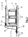
- Fig.2 is the same vehicle in a section normal to the section of the Fig.1 i.e. in the longitudinal direction of the vehicle, seen from the side.
- the motor vehicle shown in detail comprises a high-voltage battery which comprises a battery housing, wherein the battery housing has side walls 1.1 and a cover covering the side walls 1.1 at the top. 1.2.
- the side walls 1.1 and the lid 1.2 are formed in one piece by a tray 1 that is open at the bottom.
- a plurality of battery cells 2 are arranged in the battery housing, i.e. in the tray 1.
- the battery cells 2 are mounted upright within the tray 1 on a carrier plate 4, so that the electrical contacts of the battery cells 2 are directed upwards and the cell bottoms are directed downwards.
- the battery cells 2 are mounted on a cell carrier 6, which is joined to the carrier plate 4 or formed in one piece.
- Flat cooling plates 7 are arranged on the cell carrier 6, below the battery cells 2.
- the cover 1.2 of the tub 1 forms a floor panel 3 of the motor vehicle and is attached at the side edges from below to another, edge-side floor panel 3, namely screwed via screw connections 11 and additionally glued, by means of adhesive 13, between the edge-side floor panel 3 and the cover 1.2 of the tub 1.
- the edge-side floor panel 3 can be formed by the sill 9, in particular by a shell of the sill inside at the top 9.2.
- the cover 1.2 of the tub 1 has fastening points 14 for seat cross members.
- Seat cross members can be attached directly to the tub 1, in particular screwed to the cover 1.2.
- the tray 1 is attached to a side sill 9 of the motor vehicle, namely mounted from below.
- the tray 1 is attached to the sill 9 using adhesive 13 and screw connection 11.
- the Fastening to the sill 9 can be carried out at a side edge of the tray 1, which forms a flange parallel to the roadway and the cover 1.2.
- the tray 1 is in Fig.1 attached to a shell 9.1 of the sill 9 which forms the outside of the sill 9.
- An additional attachment of the tub 1 takes place, as previously described, with a shell 9.2 of the sill 9, which can be located inside and can form an upper part of the sill 9.
- a lower part of the inside of the sill 9 can be formed by the side walls 1.1 of the tub 1.
- the sill 9 can also have a central stiffener or shell 9.3.
- the central shell 9.3 can also be attached to the tub 1.
- the tub 1, in particular side walls 1.1 of the tub 1, thus form part of the supporting structure of the motor vehicle, namely the side sills 9 of the motor vehicle.
- a plurality of cross members 5 of the supporting structure of the motor vehicle are arranged within the tray 1 of the high-voltage battery, wherein the cross members 5 can be formed integrally with the cell carrier 6.
- the battery cells 2 are each mounted on the cross members 5 in the spaces between the cross members 5, so that several parallel rows of battery cells 2 run between the cross members 5.
- the battery cells 2 can be attached to the cross members 5 via mechanical joining elements 11, such as screws, for example by screwing.
- the carrier plate 4 forms the base of the high-voltage battery, covering the underside of the tray 1.
- the fastening points 16 of the carrier plate 4 are at the same Y position as the fastening points 15 of the tub 1, in particular the cast tub.
- the carrier plate 4 has recesses at the screw positions of the tub 1 so that it can be joined.
- the advantage of this design is the better flow of force in the event of a side impact, and in an even larger interior space of the battery housing.
- the fastening points 16 of the support plate are located in the Y direction between the fastening points 15 of the tub.
- a battery housing is structurally integrated into a vehicle body like an inverted tray 1 and at the same time closes off a floor assembly from below.
- An assembly adhesive system with adhesive 13 is used to join the tray 1, in combination with mechanical joining elements 11, such as screws, rivets, etc.
- the mechanical joining points 11 enable continuous production of the vehicles without the vehicle having to be removed for the adhesive 13 to harden.
- the battery modules 2 are arranged on a carrier plate 4 with an integrated cell carrier 6 and are installed from below.
- the carrier plate 4 is also designed as underrun protection and can be removed again.
- the pre-assembly of the battery housing takes place in the dismantled state.
- the cooling plates 7 are inserted into the cell carrier 6, then the cells 2 are inserted into the cell carrier from above and electrically connected to one another.
- the carrier plate 4 and the tray 1 are screwed together.
- the cell carrier 6 can be used as one-piece cast part together with the carrier plate 4, or as a multi-part welded assembly or as a combination of materials, for example the carrier plate 4 made of GRP and the cell carrier 6 made of aluminum.
- the cells 2 are connected to plug connections on the front side of the housing through a recess.
- a locking plate which also contains the plug connections, is then screwed to the housing in a gas-tight manner.
- the battery tray 1 can be designed as a one-piece die-cast component (megacasting), which can already have the seat attachment points 14 integrated. In addition, necessary connection points for components in the interior can already be included in the casting.
- a key advantage of this arrangement is the increase in installation space in the Y direction around the cross-section that a battery frame usually requires, as well as the integration of several components and the associated savings in individual parts and joining technology.
- the Z-dimension chain also becomes smaller due to the missing air gap between the base plate and the battery housing.
- Eliminating the battery frame further saves costs and weight.
Landscapes
- Engineering & Computer Science (AREA)
- Chemical & Material Sciences (AREA)
- Chemical Kinetics & Catalysis (AREA)
- Electrochemistry (AREA)
- General Chemical & Material Sciences (AREA)
- Mechanical Engineering (AREA)
- Transportation (AREA)
- Manufacturing & Machinery (AREA)
- Power Engineering (AREA)
- Sustainable Energy (AREA)
- Sustainable Development (AREA)
- Life Sciences & Earth Sciences (AREA)
- Combustion & Propulsion (AREA)
- Aviation & Aerospace Engineering (AREA)
- Battery Mounting, Suspending (AREA)
- Arrangement Or Mounting Of Propulsion Units For Vehicles (AREA)
Priority Applications (3)
| Application Number | Priority Date | Filing Date | Title |
|---|---|---|---|
| EP23161464.5A EP4432434A1 (fr) | 2023-03-13 | 2023-03-13 | Véhicule automobile doté d'une batterie haute tension |
| US18/594,071 US20240313324A1 (en) | 2023-03-13 | 2024-03-04 | Motor vehicle with a high voltage battery |
| CN202410276507.3A CN118636644A (zh) | 2023-03-13 | 2024-03-12 | 带有高压电池的机动车 |
Applications Claiming Priority (1)
| Application Number | Priority Date | Filing Date | Title |
|---|---|---|---|
| EP23161464.5A EP4432434A1 (fr) | 2023-03-13 | 2023-03-13 | Véhicule automobile doté d'une batterie haute tension |
Publications (1)
| Publication Number | Publication Date |
|---|---|
| EP4432434A1 true EP4432434A1 (fr) | 2024-09-18 |
Family
ID=85601660
Family Applications (1)
| Application Number | Title | Priority Date | Filing Date |
|---|---|---|---|
| EP23161464.5A Pending EP4432434A1 (fr) | 2023-03-13 | 2023-03-13 | Véhicule automobile doté d'une batterie haute tension |
Country Status (3)
| Country | Link |
|---|---|
| US (1) | US20240313324A1 (fr) |
| EP (1) | EP4432434A1 (fr) |
| CN (1) | CN118636644A (fr) |
Families Citing this family (3)
| Publication number | Priority date | Publication date | Assignee | Title |
|---|---|---|---|---|
| DE102020110744A1 (de) * | 2020-04-21 | 2021-11-18 | Bayerische Motoren Werke Aktiengesellschaft | Verfahren zum Anordnen eines mehrere Batteriemodule aufweisenden Hochvoltspeichers an einer Tragstruktur eines Kraftwagens sowie Hochvoltspeicheranordnung |
| EP4257391B1 (fr) * | 2022-04-06 | 2025-12-10 | Nemak, S.A.B. de C.V. | Porte-batterie monobloc, ainsi que procédé de moulage sous pression d'un porte-batterie monobloc |
| JP2024024758A (ja) * | 2022-08-10 | 2024-02-26 | トヨタ自動車株式会社 | 車両前部構造 |
Citations (3)
| Publication number | Priority date | Publication date | Assignee | Title |
|---|---|---|---|---|
| US20140338999A1 (en) * | 2011-12-09 | 2014-11-20 | Honda Motor Co., Ltd. | Structure for mounting battery pack on vehicle |
| WO2019016081A1 (fr) * | 2017-07-18 | 2019-01-24 | Mahle International Gmbh | Ensemble accumulateur |
| DE102021109394A1 (de) * | 2021-04-14 | 2022-10-20 | Bayerische Motoren Werke Aktiengesellschaft | Antriebsbatteriegehäuse für ein Kraftfahrzeug |
Family Cites Families (4)
| Publication number | Priority date | Publication date | Assignee | Title |
|---|---|---|---|---|
| JP5734453B2 (ja) * | 2011-11-14 | 2015-06-17 | 本田技研工業株式会社 | バッテリの車載構造 |
| DE102016115647B3 (de) * | 2016-08-23 | 2017-12-14 | Benteler Automobiltechnik Gmbh | Batterieträger für ein Elektrokraftfahrzeug sowie Verfahren zum Bestücken und Montieren eines Batterieträgers |
| US10688854B2 (en) * | 2018-03-26 | 2020-06-23 | Ford Global Technologies, Llc | Electric vehicle with integrated battery and floor assembly |
| EP4308398A1 (fr) * | 2021-03-18 | 2024-01-24 | Grouper Acquistition Company, LLC | Plateau de batterie de véhicule et son procédé de fabrication |
-
2023
- 2023-03-13 EP EP23161464.5A patent/EP4432434A1/fr active Pending
-
2024
- 2024-03-04 US US18/594,071 patent/US20240313324A1/en active Pending
- 2024-03-12 CN CN202410276507.3A patent/CN118636644A/zh active Pending
Patent Citations (3)
| Publication number | Priority date | Publication date | Assignee | Title |
|---|---|---|---|---|
| US20140338999A1 (en) * | 2011-12-09 | 2014-11-20 | Honda Motor Co., Ltd. | Structure for mounting battery pack on vehicle |
| WO2019016081A1 (fr) * | 2017-07-18 | 2019-01-24 | Mahle International Gmbh | Ensemble accumulateur |
| DE102021109394A1 (de) * | 2021-04-14 | 2022-10-20 | Bayerische Motoren Werke Aktiengesellschaft | Antriebsbatteriegehäuse für ein Kraftfahrzeug |
Also Published As
| Publication number | Publication date |
|---|---|
| CN118636644A (zh) | 2024-09-13 |
| US20240313324A1 (en) | 2024-09-19 |
Similar Documents
| Publication | Publication Date | Title |
|---|---|---|
| DE102017205447B4 (de) | Bodenstruktur für ein elektrisch angetriebenes Kraftfahrzeug | |
| EP4432434A1 (fr) | Véhicule automobile doté d'une batterie haute tension | |
| DE102017118120B4 (de) | Verfahren zur Herstellung eines elektrisch angetriebenen Fahrzeugs | |
| DE102017011994B3 (de) | Energiespeichereinheit für ein Kraftfahrzeug, Befestigungsanordnung einer solchen Energiespeichereinheit an einem Aufbau eines Kraftfahrzeugs, sowie Kraftfahrzeug mit einer solchen Energiespeichereinheit | |
| DE102017217814B4 (de) | Batteriegehäuse für ein Fahrzeug | |
| DE102017105709A1 (de) | Batterieaufnahme mit Verstärkungsstruktur und Verwendung | |
| DE102016115037A1 (de) | Batteriekasten mit seitlicher Verstärkung | |
| WO2021043562A1 (fr) | Groupe de plancher accumulateur d'énergie pour un véhicule à moteur | |
| WO2013053433A1 (fr) | Structure de châssis pour voiture particulière à propulsion électrique | |
| DE102016203209A1 (de) | Zumindest teilweise elektrisch betreibbares Kraftfahrzeug | |
| DE102018215954B4 (de) | Kraftfahrzeug und Batterie | |
| WO2017207502A1 (fr) | Logement de batterie et utilisation d'un logement de batterie | |
| DE102020133961A1 (de) | Energiespeicher-Bodengruppe für einen elektrisch antreibbaren Kraftwagen | |
| DE102018113812A1 (de) | Verfahren zur Herstellung einer Karosseriestruktur eines Kraftfahrzeugs | |
| DE102015117654A1 (de) | Fahrzeug | |
| DE102008014829A1 (de) | Schutzgehäuse für eine galvanische Zelle in einem Kraftfahrzeug | |
| DE102020214105A1 (de) | Fahrzeuglängsträger | |
| DE102021119166A1 (de) | Kraftfahrzeug mit einer Karosserie und einem Antriebsenergiespeicher | |
| EP4431325B1 (fr) | Véhicule automobile doté d'une batterie haute tension | |
| DE102016203210A1 (de) | Zumindest teilweise elektrisch betreibbares Kraftfahrzeug | |
| WO2020007779A1 (fr) | Module pour véhicule à moteur | |
| DE102020114935B3 (de) | Kraftfahrzeug mit unterteiltem Aggregateraum | |
| EP4631774A1 (fr) | Véhicule automobile doté d'une batterie haute tension | |
| DE102018124541A1 (de) | Kraftfahrzeug mit einer Kraftfahrzeugkarosserie und einer Speicherzellenbaugruppe | |
| DE102023002333A1 (de) | Batteriegehäuse und Batterieanordnung |
Legal Events
| Date | Code | Title | Description |
|---|---|---|---|
| PUAI | Public reference made under article 153(3) epc to a published international application that has entered the european phase |
Free format text: ORIGINAL CODE: 0009012 |
|
| STAA | Information on the status of an ep patent application or granted ep patent |
Free format text: STATUS: THE APPLICATION HAS BEEN PUBLISHED |
|
| STAA | Information on the status of an ep patent application or granted ep patent |
Free format text: STATUS: REQUEST FOR EXAMINATION WAS MADE |
|
| AK | Designated contracting states |
Kind code of ref document: A1 Designated state(s): AL AT BE BG CH CY CZ DE DK EE ES FI FR GB GR HR HU IE IS IT LI LT LU LV MC ME MK MT NL NO PL PT RO RS SE SI SK SM TR |
|
| 17P | Request for examination filed |
Effective date: 20240906 |
|
| RBV | Designated contracting states (corrected) |
Designated state(s): AL AT BE BG CH CY CZ DE DK EE ES FI FR GB GR HR HU IE IS IT LI LT LU LV MC ME MK MT NL NO PL PT RO RS SE SI SK SM TR |