EP4432468A2 - Integrierte ekg-elektrode und antennenstrahler - Google Patents
Integrierte ekg-elektrode und antennenstrahler Download PDFInfo
- Publication number
- EP4432468A2 EP4432468A2 EP24192702.9A EP24192702A EP4432468A2 EP 4432468 A2 EP4432468 A2 EP 4432468A2 EP 24192702 A EP24192702 A EP 24192702A EP 4432468 A2 EP4432468 A2 EP 4432468A2
- Authority
- EP
- European Patent Office
- Prior art keywords
- antenna
- circuitry
- conductive element
- biometric
- decoupling
- Prior art date
- Legal status (The legal status is an assumption and is not a legal conclusion. Google has not performed a legal analysis and makes no representation as to the accuracy of the status listed.)
- Pending
Links
Images



Classifications
-
- A—HUMAN NECESSITIES
- A61—MEDICAL OR VETERINARY SCIENCE; HYGIENE
- A61B—DIAGNOSIS; SURGERY; IDENTIFICATION
- A61B5/00—Measuring for diagnostic purposes; Identification of persons
- A61B5/24—Detecting, measuring or recording bioelectric or biomagnetic signals of the body or parts thereof
- A61B5/30—Input circuits therefor
- A61B5/307—Input circuits therefor specially adapted for particular uses
- A61B5/308—Input circuits therefor specially adapted for particular uses for electrocardiography [ECG]
-
- A—HUMAN NECESSITIES
- A61—MEDICAL OR VETERINARY SCIENCE; HYGIENE
- A61B—DIAGNOSIS; SURGERY; IDENTIFICATION
- A61B5/00—Measuring for diagnostic purposes; Identification of persons
- A61B5/0002—Remote monitoring of patients using telemetry, e.g. transmission of vital signals via a communication network
- A61B5/0004—Remote monitoring of patients using telemetry, e.g. transmission of vital signals via a communication network characterised by the type of physiological signal transmitted
- A61B5/0006—ECG or EEG signals
-
- A—HUMAN NECESSITIES
- A61—MEDICAL OR VETERINARY SCIENCE; HYGIENE
- A61B—DIAGNOSIS; SURGERY; IDENTIFICATION
- A61B5/00—Measuring for diagnostic purposes; Identification of persons
- A61B5/0002—Remote monitoring of patients using telemetry, e.g. transmission of vital signals via a communication network
- A61B5/0015—Remote monitoring of patients using telemetry, e.g. transmission of vital signals via a communication network characterised by features of the telemetry system
- A61B5/002—Monitoring the patient using a local or closed circuit, e.g. in a room or building
-
- A—HUMAN NECESSITIES
- A61—MEDICAL OR VETERINARY SCIENCE; HYGIENE
- A61B—DIAGNOSIS; SURGERY; IDENTIFICATION
- A61B5/00—Measuring for diagnostic purposes; Identification of persons
- A61B5/24—Detecting, measuring or recording bioelectric or biomagnetic signals of the body or parts thereof
- A61B5/25—Bioelectric electrodes therefor
- A61B5/279—Bioelectric electrodes therefor specially adapted for particular uses
- A61B5/28—Bioelectric electrodes therefor specially adapted for particular uses for electrocardiography [ECG]
-
- A—HUMAN NECESSITIES
- A61—MEDICAL OR VETERINARY SCIENCE; HYGIENE
- A61B—DIAGNOSIS; SURGERY; IDENTIFICATION
- A61B5/00—Measuring for diagnostic purposes; Identification of persons
- A61B5/24—Detecting, measuring or recording bioelectric or biomagnetic signals of the body or parts thereof
- A61B5/316—Modalities, i.e. specific diagnostic methods
- A61B5/318—Heart-related electrical modalities, e.g. electrocardiography [ECG]
- A61B5/332—Portable devices specially adapted therefor
-
- A—HUMAN NECESSITIES
- A61—MEDICAL OR VETERINARY SCIENCE; HYGIENE
- A61B—DIAGNOSIS; SURGERY; IDENTIFICATION
- A61B5/00—Measuring for diagnostic purposes; Identification of persons
- A61B5/68—Arrangements of detecting, measuring or recording means, e.g. sensors, in relation to patient
- A61B5/6801—Arrangements of detecting, measuring or recording means, e.g. sensors, in relation to patient specially adapted to be attached to or worn on the body surface
- A61B5/6802—Sensor mounted on worn items
- A61B5/681—Wristwatch-type devices
-
- H—ELECTRICITY
- H01—ELECTRIC ELEMENTS
- H01Q—ANTENNAS, i.e. RADIO AERIALS
- H01Q1/00—Details of, or arrangements associated with, antennas
- H01Q1/27—Adaptation for use in or on movable bodies
- H01Q1/273—Adaptation for carrying or wearing by persons or animals
-
- H—ELECTRICITY
- H01—ELECTRIC ELEMENTS
- H01Q—ANTENNAS, i.e. RADIO AERIALS
- H01Q1/00—Details of, or arrangements associated with, antennas
- H01Q1/44—Details of, or arrangements associated with, antennas using equipment having another main function to serve additionally as an antenna, e.g. means for giving an antenna an aesthetic aspect
-
- H—ELECTRICITY
- H01—ELECTRIC ELEMENTS
- H01Q—ANTENNAS, i.e. RADIO AERIALS
- H01Q1/00—Details of, or arrangements associated with, antennas
- H01Q1/50—Structural association of antennas with earthing switches, lead-in devices or lightning protectors
-
- H—ELECTRICITY
- H01—ELECTRIC ELEMENTS
- H01Q—ANTENNAS, i.e. RADIO AERIALS
- H01Q1/00—Details of, or arrangements associated with, antennas
- H01Q1/52—Means for reducing coupling between antennas; Means for reducing coupling between an antenna and another structure
- H01Q1/526—Electromagnetic shields
-
- H—ELECTRICITY
- H01—ELECTRIC ELEMENTS
- H01Q—ANTENNAS, i.e. RADIO AERIALS
- H01Q13/00—Waveguide horns or mouths; Slot antennas; Leaky-waveguide antennas; Equivalent structures causing radiation along the transmission path of a guided wave
- H01Q13/10—Resonant slot antennas
-
- H—ELECTRICITY
- H01—ELECTRIC ELEMENTS
- H01Q—ANTENNAS, i.e. RADIO AERIALS
- H01Q5/00—Arrangements for simultaneous operation of antennas on two or more different wavebands, e.g. dual-band or multi-band arrangements
- H01Q5/30—Arrangements for providing operation on different wavebands
- H01Q5/378—Combination of fed elements with parasitic elements
-
- H—ELECTRICITY
- H03—ELECTRONIC CIRCUITRY
- H03H—IMPEDANCE NETWORKS, e.g. RESONANT CIRCUITS; RESONATORS
- H03H7/00—Multiple-port networks comprising only passive electrical elements as network components
- H03H7/38—Impedance-matching networks
-
- A—HUMAN NECESSITIES
- A61—MEDICAL OR VETERINARY SCIENCE; HYGIENE
- A61B—DIAGNOSIS; SURGERY; IDENTIFICATION
- A61B2505/00—Evaluating, monitoring or diagnosing in the context of a particular type of medical care
- A61B2505/07—Home care
-
- A—HUMAN NECESSITIES
- A61—MEDICAL OR VETERINARY SCIENCE; HYGIENE
- A61B—DIAGNOSIS; SURGERY; IDENTIFICATION
- A61B2505/00—Evaluating, monitoring or diagnosing in the context of a particular type of medical care
- A61B2505/09—Rehabilitation or training
-
- H—ELECTRICITY
- H01—ELECTRIC ELEMENTS
- H01Q—ANTENNAS, i.e. RADIO AERIALS
- H01Q7/00—Loop antennas with a substantially uniform current distribution around the loop and having a directional radiation pattern in a plane perpendicular to the plane of the loop
-
- H—ELECTRICITY
- H01—ELECTRIC ELEMENTS
- H01Q—ANTENNAS, i.e. RADIO AERIALS
- H01Q9/00—Electrically-short antennas having dimensions not more than twice the operating wavelength and consisting of conductive active radiating elements
- H01Q9/04—Resonant antennas
- H01Q9/0407—Substantially flat resonant element parallel to ground plane, e.g. patch antenna
- H01Q9/0421—Substantially flat resonant element parallel to ground plane, e.g. patch antenna with a shorting wall or a shorting pin at one end of the element
Definitions
- circuits of a computing device that share at least one conductive element.
- These can include circuits for communication, such as antenna circuits, as well as circuits for making biometric or physiological measurements for a user.
- the use of the conductive element can vary by circuit, such as an antenna radiator for a radio frequency (RF) circuit or a dry electrode for an electrocardiography (ECG) circuit.
- the circuitry sharing a conductive element can utilize signals obtained over different frequency ranges. Those ranges can be used to select decoupling circuitry (or elements) that can enable the respective circuits to obtain signals over a respective frequency range and exclude signals over one or more other frequency ranges corresponding to other circuitry sharing the circuit.
- Such an approach allows for concurrent independent operation of the various circuits sharing a conductive element.
- FIG. 1 illustrates an example wearable device 100 that can be utilized in accordance with various embodiments.
- the device is a smart watch, although fitness trackers and other types of devices can be utilized as well.
- this device is shown to be worn on a user's wrist there can be other types of devices worn on, or proximate to, other portions of a user's body as well, such as on a finger, in an ear, around a chest, etc.
- wireless connectivity enabling data transfer between a networked device or computing device and the wearable device.
- a cellular or Wi-Fi connection can be used to transmit data across at least one network such as the Internet or a cellular network, among other such options.
- ECG electrocardiography
- a conductive electrode is often brought into contact with the skin of the person to be monitored.
- a person is wearing a wearable device 100 on his or her arm 102, and can bring one or more fingers 106 (or palm, etc.) into contact with an exposed electrode of the device.
- the electrode is at least a portion of a metallic ring 104 that is part of the housing around a display screen 108 of the wearable device, although other types and forms of electrodes can be used as well within the scope of the various embodiments.
- the electrode can be connected to an ECG circuit that can detect small changes in electrical charge on the skin that vary with the user's heartbeat. ECG data can be monitored over time to attempt to determine irregularities in heartbeat that might indicate serious cardiac issues. Conventional ECG measurements are obtained by measuring the electrical potential of the heart over a period of time, typically corresponding to multiple cardiac cycles. By a user placing his or her fingers on the exposed electrode for a minimum period of time, during which ECG measurements are taken, an application executing on the wearable device can collect and analyze the ECG data and provide feedback to the user.
- approaches discussed herein can utilize one or more ECG electrodes as communications antenna elements. Such an approach can reduce the number of elements (including separate antenna(s) and electrode(s)) needed to support the same functionality on a specific device.
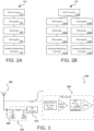
- FIG. 2A illustrates a simplified block diagram 200 of one such implementation that can be utilized in accordance with various embodiments.
- This diagram illustrates antenna matching circuitry 202 and ECG circuitry 210, which each can include any appropriate circuitry known, used, or appropriate for such functionality, including but not limited to those discussed herein.
- the antenna matching circuitry 202 and ECG circuitry 210 can share a single electrode 206 in this example, although other combinations or approaches can be used as well within the scope of the various embodiments.
- at least one electrode 206 must be isolated from extended contact with the skin of the user, such as from the wrist upon which a smart watch or fitness tracking device might be worn.
- An example electrode is metallic and of a sufficiently large size, at least relative to the size of the device, in order to allow for good contact with the skin of the user.
- an electrode has a size on the order of at least 150 mm 2 .
- Such electrode can be made of stainless steel, although any conductive metal material or metal alloy may be considered as long as the contact surface is not subject to oxidation during exposure to air or moisture.
- the antenna radiators may need to occupy a large portion of the volume within or on the device.
- the antenna circuitry is typically placed relatively close to the antenna radiator or electrode, while there may be no restriction or advantage to placing ECG circuitry relatively close to the antenna circuitry.
- the ECG circuitry can be placed at an optimal location for the particular device design.
- An approach such as that illustrated in FIG. 2A enables at least one metallic piece, or other conductive element, to be utilized concurrently as an ECG electrode and an antenna radiator.
- additional circuits that utilize similar conductive elements might share such an element as well, such as where the frequency range to be analyzed for a circuit or application falls sufficiently outside the frequency range of any other circuit or application sharing a particular electrode.
- the ECG circuitry 210 is connected to the shared electrode 206 (also functioning as an antenna radiator) via a decoupling circuit or element 208 that isolates the ECG circuitry 210 over a range of radio frequency (RF) frequencies (around 700MHz to around 3GHz, or above 600MHZ for at least some embodiments utilizing LTE Cat M1, GNSS, Bluetooth, and Wi-Fi protocols, or up to about 6GHz in other embodiments) from the antenna matching circuitry 202, which can be connected to one or more RF systems.
- RF radio frequency
- the antenna matching circuitry 202 can be connected to the shared electrode/radiator 206 via a second decoupling circuit or element 204 that isolates it at a range of low frequencies (around 0Hz (DC) to around 150 kHz for some embodiments, although for sufficient isolation a higher cutoff frequency can be utilized) from the ECG circuitry 210.
- the impact of the ECG circuit on the antenna matching circuit can be reduced by using inductors or ferrite beads that have high impedance at RF frequencies instead of high impedance resistors as discussed elsewhere herein. Since ECG circuitries have high impedance inputs, the relatively lower impedance decoupling component 208 will have a negligible impact on the ECG system in at least some embodiments.
- Additional isolation can be achieved in some embodiments by using a shunt capacitor to ground after the series resistor/inductor that would present a short circuit to ground at RF frequencies.
- a shunt capacitor to ground after the series resistor/inductor that would present a short circuit to ground at RF frequencies.
- Decoupling the circuits also enables them to function independently in at least some embodiments, although in other embodiments the conductive elements might be shared but only operated one at a time for a specific circuit, such as where a specific communication protocol utilizes a frequency range that is relatively close to that of the ECG circuit or other circuit sharing the conductive element. If there are more than two circuits sharing such an element, then any subset of the circuits that are decoupled can concurrently utilize the element at a specific time.
- Decoupling elements can be used to filter or otherwise attenuate signals from one circuitry element to another.
- one decoupling element can cause the ECG signal to not significantly load the communications circuitry (and/or vice versa), providing a few tenths of a decibel of load (e.g., 0.1 dB, 0.2 dB, 0.3 dB, 0.4 dB, or 0.5).
- FIG. 2B illustrates an example alternative to FIG. 2A whereby there are two electrodes 206a and 206b each connected to respective antenna matching circuitry 202a and 202b using respective decouplers 204a, 204b, 208a, and 208b. The two electrodes can then be connected to a single ECG circuitry element 210.
- FIG. 3 illustrates a first example subsystem 300 that can be utilized in accordance with various embodiments.
- a conductive element 302 is shared as an electrode for an ECG circuit 308 and a radiator for an antenna matching circuit 304.
- the ECG circuit and antenna matching circuit can be on the same or different printed circuit boards (PCB), chips, etc., in various embodiments.
- PCB printed circuit boards
- This example represents a monopole antenna concept wherein there is no ground path from the antenna radiator to system PCB ground.
- a first decoupling element 306 is positioned between the shared conductive element 302 and the antenna matching circuit 304, which in turn feeds into an RF chipset 312.
- the first decoupling element 306 is selected based at least in part upon the relative operating frequencies of the ECG circuit and the antenna matching circuit, such that only frequencies within the range for the antenna matching circuit are passed along to the antenna matching circuit 304, or at least that frequencies in the range for the ECG circuit are not significantly passed along to the antenna matching circuit 304.
- Such cross-talk can be digitally attenuated as part of a signal analysis procedure.
- a second decoupling element 310 can be selected based at least in part upon the relative operating frequencies of the ECG circuit and the antenna matching circuit, such that only frequencies within the range for the ECG are passed along to the ECG circuit 308, or at least that frequencies in the range for the antenna matching circuit are not significantly passed along to the ECG circuit 308.
- any appropriate circuitry known, used, or developed for such purposes can be utilized as well within the scope of the various embodiments. As at least some circuits of these types are well known in the art, they will not be discussed in detail herein.
- the first decoupling element 306 (or circuit) is a 33pF capacitor aligned in series for decoupling of the ECG signal, although other capacitors can be used as well in various embodiments, such as capacitors with values between about 20pF and about 100pF, or even values up to 100nF.
- the second decoupling element 310 (or circuit) in this example is a 22k resistor used for RF antenna decoupling, which in various embodiments is preferred to be placed closer to the conductive element 302 in this embodiment.
- This decoupling element can alternatively be a resistor having a value between 5K ohms and 100K ohms, or an inductor with a value between about 30nH to about 1uH in some embodiments, or a ferrite bead which provides 1000ohms or high impedance at the operating frequencies of the antenna matching circuit.
- a second contact point for the ECG circuit 308 as illustrated can be connected to a second electrode that is not shared with the antenna matching circuit 306.
- the capacitor of the first decoupling circuit 306 provides an open circuit for the signals at the ECG frequency, and the resistor of the second decoupling circuit 310 will only allow signals at the antenna frequency to pass to the antenna matching circuit.
- the first and second decoupling elements can be any appropriate decoupling elements capable of filtering out specific frequencies, or allowing only specific frequencies, to be propagated from a shared conductive element.
- the decoupling elements (or circuits) can include elements such as resistors, inductors, capacitors, and ferrite beads, which can have values or ranges as specified herein. As mentioned, the values can be determined based at least in part upon the respective circuit to which a range of frequencies are to pass, and other circuits sharing the conductive element whose frequencies are not to pass via the decoupling element (or circuit).
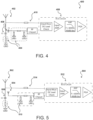
- FIG. 4 illustrates another example subsystem 400 that can be utilized in accordance with various embodiments.
- a conductive element 402 is shared as an electrode for an ECG circuit 408, via a respective decoupling element 410 (or circuit), and a radiator for an antenna matching circuit 404, via a pair of (or multiple) decoupling elements 406 (or decoupling circuits).
- the antenna is of a different type that that of FIG. 3 , being a loop antenna, slot antenna, or inverted-F antenna (IFA), among other such options.
- IFA inverted-F antenna
- Two or more decoupling elements 406 for the antenna matching circuit 404 can be of the same type or different types.
- the two or more decoupling elements 406 can have the same value or different values, such as two or more 33pF capacitors for decoupling to the ECG signal.
- the capacitor range can also be the same as is discussed with respect to the corresponding capacitors of FIG. 3 .
- the ECG circuit in this example cannot be DC grounded, which necessitates the capacitive element in each ground path.
- FIG. 5 illustrates another example subsystem 500 that can be utilized in accordance with various embodiments.
- a conductive element 502 of a pair of conductive elements 502, 504 is shared as an electrode for an ECG circuit 512, via a respective decoupling element 514.
- an electrode 502 can then function as an antenna radiator which is capacitively coupled through a feeding element 504 connected to an antenna matching circuit 510.
- the electrode 502 has one or more ground paths to the system PCB ground each via a decoupling element 508.
- the antenna is of yet a different type, here being a parasitic antenna or capacitive feed antenna that utilizes a ground path to the parasitic radiator or capacitive feed radiator.
- the capacitive feed antenna can be multiple type of antennas, for example a capacitive feed monopole antenna, a capacitive feed loop antenna, or a capacitive feed slot antenna.
- a parasitic antenna or a capacitive feed antenna is also referred to as a passive antenna in some situations as it is not electrically connected to anything else, namely any other circuits on the device.
- the conductive element 502 can function as a passive antenna element.
- at least a decoupling element 508 is utilized along each ground path, which can be a capacitor of 33pF or another such value discussed for such purposes herein.
- the electrode or other capacitive element(s) can take many forms on, or in, the device, although for ECG and various other applications at least a portion of the electrode must be exposed or otherwise accessible to the skin of the user.
- the exposed electrode is utilized with one or more other electrodes that interface with the skin of the wrist or other such location, as may be based upon the type of device or preference of the user.
- the electrode can be part of the device housing, or part of a conductive ring around a screen or element of the device.
- the electrode can also be one or more rods or planar elements positioned at a periphery of the device casing, among other such options.
- surface-mounted stainless steel strip can be utilized as an ECG electrode.
- the electrode strip in one embodiment is adhered to the outside surface of a metal housing but is isolated from the metal housing by one or more layers of adhesive or a non-conductive polybutylene terephthalate (PBT) material manufactured using a process such as nano-molding.
- PBT polybutylene terephthalate
- nano-molding can be utilized to generate a ring or loop design, where there may be one or more conductive elements, or elements of one or more pieces or regions. In some embodiments there might be multiple splits, such as may correspond to four separate elements, each with a different feed point.
- Electrodes can be used as electrodes as well, with each capable of being used for at least one different circuit in some embodiments.
- a top electrode might be used for ECG and Wi-Fi circuitry, while a bottom electrode might be used for LTE communications.
- multiple conductive elements utilized for the ECG are utilized by a single antenna circuit and protocol to take advantage of multipathing of signals received/transmitted by the multiple conductive elements (e.g., multi-stream beamforming, spatial multiplexing, and diversity coding as well as other multiple-in and multiple-out (MIMO) or similar techniques).
- MIMO multiple-in and multiple-out
- measurements can be taken concurrently at any time, as discussed in some embodiments where ECG measurements might be taken infrequently, such as only once per day, it might be beneficial to limit communications during that time for a communications circuit utilizing that electrode as an antenna element.
- the communications circuit can temporarily impose a rate limit or a power limit or otherwise stop communications except for those necessary to maintain the communications link.
- certain frequencies or encoding techniques within a communications specification might not be fully filtered by the ECG decoupling element.
- the communications circuitry can minimize use of such frequencies or encoding techniques. For example, a protocol using adaptive frequency-hopping spread spectrum can be programmed to "skip" over frequencies that cause problems for ECG measurement.
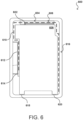
- FIG. 6 illustrates a top view of an example electronic device 600 having a metal plate 608 within a metal housing 616 forming a slot antenna 610 that is excited by a monopole antenna 606.
- the housing (such as a metal housing) 616 may be designed to accommodate a display that will be worn on a person's wrist.
- a wristband (not shown) may be connected to the opposing ends of the metal housing, and the completed unit may be worn on someone's wrist.
- the metal housing may be designed to conform better to the cross-sectional curvature of a person's forearm and the interior of the metal housing may be occupied by various electrical components, including a PCB or FPCB (Flexible Printed Circuit Board) that includes, for example, various sensors, processors, power management components, etc.
- the metal housing may include additional features, such as a metal button bracket 612, to support other elements within the metal housing.
- the slot antenna 610 is structured as a gap between the metal plate 608 and the metal housing 616 (including the metal button bracket 612) stopped at two ends with grounding contacts 614, 620 between the metal plate and the metal housing.
- the slot antenna can be configured as a half-wavelength slot antenna (e.g., a length of about 6.25 cm for Bluetooth communication).
- the slot antenna is not directly driven by any element (e.g., an antenna feed or coaxial cable) coupled to the printed circuit board or other similar component.
- a third grounding pin 618 can be included to improve performance.
- the grounding contacts 614, 620 can be used to tune the slot resonance of the slot antenna (e.g., to resonate within the Bluetooth band).
- the third grounding pin 618 can be used for reducing or preventing unwanted resonances in the remaining gap between the metal housing and the metal plate that may reduce the radiation efficiency of the slot antenna 610.
- the grounding clips can be configured as a spring contact or other type of electrical connection.
- the grounding clips can include elements that terminate in a leaf spring that presses against the metal housing or metal button bracket.
- the example monopole antenna 606 is designed to excite the slot antenna 610 in a targeted mode.
- the monopole antenna includes a flex printed circuit board (FPCB) as the monopole radiator 602 on a monopole antenna carrier 604 made of a plastic mechanical component.
- the FPCB 602 is assembled on the surface of the carrier 604 and the carrier is placed inside the metal housing 616.
- the carrier can be attached to the metal housing or other component of the device.
- Biometric monitoring devices including wrist-worn biometric monitoring devices, can be configured to send and receive biometric and other data to and from one or more separate electronic devices. To wirelessly send and receive data, such monitoring devices require the use of one or more antennas in the device.
- An example antenna architecture for wearable electronic devices includes two portions.
- the antenna architectures include a monopole antenna having a monopole radiator on a plastic carrier implemented at a top of a display area within a metal housing of the device.
- the monopole radiator is connected through an antenna clip on a printed circuit board (PCB) to a radio frequency (RF) engine.
- the monopole antenna can be implemented as a flex film antenna radiator assembled on, for example, a plastic carrier.
- the monopole radiator can generate electromagnetic fields to induce the slot antenna to transmit or receive radio frequency signals.
- the antenna can be designed to be particularly receptive to (or emissive of) radio frequency energy at frequencies within the frequency band(s) for the wireless communications protocol(s) that the antenna is designed to support, and the antenna can also be designed to not be particularly receptive to (or emissive of) radio frequency energy at frequencies outside of the frequency band(s).
- Antennas may achieve such selectivity by virtue of their physical geometry and the dimensions that define that geometry.
- the antenna architectures include a slot antenna formed by a gap between a metal (and/or conductive) plate and the metal housing.
- the slot antenna radiates RF signals from the slot structure through a display module, a touch module, and a glass window.
- the monopole radiator and slot antenna are capacitively coupled such that the monopole radiator generates a varying electric field that induces varying electric fields at the slot antenna, resulting in the reception and/or emission of RF signals.
- This coupling of electric fields between the monopole radiator and the slot antenna allows for RF signals to be transmitted from and received by the device.
- the monopole radiator is positioned within the slot area to excite the slot antenna through electromagnetic field coupling.
- the dimensions of the slot antenna and monopole antenna can be tuned to achieve targeted communication frequency bands.
- the monopole antenna portion can be tuned to have a certain length and a matching circuit on the PCB may be utilized to tune the antenna impedance to achieve targeted performance characteristics.
- the metal plate and/or metal housing can be conductive.
- the metal plate and/or metal housing can include one or more materials that include a conductivity of 1E5 Siemens/m and/or higher.
- the disclosed monopole-excited slot antenna reduces the dead band of the display window or provide a desirably or advantageously small dead band at a top of the display window.
- the monopole antenna component that excites the slot antenna can provide a targeted excitation for the slot antenna with a reduced distance between a top side of the metal housing and a display module relative to a pure monopole antenna or inverted-F antenna (IFA) architecture with similar antenna performance.
- IFA inverted-F antenna
- the disclosed monopole-excited slot antenna accommodates a device architecture having a printed circuit board (PCB) mounted close to the bottom of a metal housing.
- PCB printed circuit board
- the PCB may require the PCB to be mounted above the battery to achieve suitable performance, manufacturing costs, and/or mechanical complexity.
- the battery size is reduced relative to devices that incorporate the antenna architectures disclosed herein that allow the battery to be placed above the PCB.
- the disclosed monopole-excited slot antenna design resides entirely within the metal housing.
- this facilitates manufacturing the device to be water resistant and/or swim proof.
- vias, or holes in the metal housing may be required to send and receive electrical signals to the portion of the antenna outside of the metal housing. These vias or holes may compromise any water-tight capabilities of the device or may undesirably increase the cost of making such a device water resistant and/or swim proof.
- the disclosed monopole-excited slot antenna designs exert no contact pressure force on the glass window.
- this facilitates manufacturing the device to be water resistant and/or swim proof, creating water-tight seals for junctions between components.
- the display window may tend to separate from the metal housing, compromising the water-tight seal.
- Example monopole-excited slot antenna functions by using a capacitively-coupled monopole antenna radiator to excite an antenna slot.
- the disclosed antenna design may be advantageous due at least in part to being mechanically simpler (e.g., not requiring the using of a coaxial cable or other transmission line from the PCB to the antenna) resulting in a lower cost and increased ease of manufacture.
- Various implementations discussed herein may be used, for example, to provide a monopole-excited slot antenna that provides Bluetooth functionality, including Bluetooth Low Energy (Bluetooth LE or BTLE) functionality.
- Bluetooth LE Bluetooth Low Energy
- Such a compact and efficient antenna may be of particular use in highly-integrated devices having a small form factor.
- the disclosed antennas can be used in biometric monitoring devices, e.g., wearable devices that track, report, and communicate various biometric measurements, e.g., distance traveled, steps taken, flights of stairs climbed, etc.
- biometric monitoring devices e.g., wearable devices that track, report, and communicate various biometric measurements, e.g., distance traveled, steps taken, flights of stairs climbed, etc.
- Such devices may take the form of a small device that is clipped to a person's clothing or worn on a person's wrist.
- Such a device may, for example, contain various processors, printed circuit boards, sensors, triaxial accelerometers, triaxial gyroscopes, triaxial magnetometers, an altimeter, a display, a vibramotor, a rechargeable battery, a recharging connector, and an input button all within a metal housing that measures approximately between 1.62" and 2" in length, 0.75" and 0.85" in width, and 0.3" and 0.44" in thickness.
- a monopole-excited slot antenna may be used in such a device to provide RF communication in a water resistant and/or swim-proof wearable device, to reduce the dead band of a display window, and/or to provide a more cost-efficient and mechanically simple device.
- monopole-excited slot antennas may provide the ability to offer a more compact communications solution than might otherwise be possible, allowing additional volume within the metal housing to be made available for other purposes, such as a larger battery.
- Such dimensions may prove to be particularly well-suited to RF communications in the Bluetooth wireless protocol bands, e.g., 2402 MHz to 2480 MHz.
- Monopole-excited slot antenna antennas that support other wireless communications protocols may also be designed using the principles outlined herein.
- the disclosed antenna architectures may be configured or dimensioned to be suitable for use with wireless networks and radio technologies, such as wireless wide area network (WWAN) (e.g., cellular) and/or wireless local area network (WLAN) carriers.
- WWAN wireless wide area network
- WLAN wireless local area network
- wireless networks and radio technologies include but are not limited to Long Term Evolution (LTE) frequency bands or other cellular communications protocol bands, GPS (Global Positioning System) or GNSS (Global Navigation Satellite System) frequency bands, ANT TM , 802.11, and ZigBee TM , for example, as well as frequency bands associated with other communications standards.
- LTE Long Term Evolution
- GPS Global Positioning System
- GNSS Global Navigation Satellite System
- ANT TM TM
- 802.11 Global Navigation Satellite System
- ZigBee TM ZigBee TM
- biometric monitoring device is used herein according to its broad and ordinary meaning, and may be used in various contexts herein to refer to any type of biometric tracking devices, personal health monitoring devices, portable monitoring devices, portable biometric monitoring devices, or the like.
- biometric monitoring devices in accordance with the present disclosure may be wearable devices, such as may be designed to be worn (e.g., continuously) by a person (i.e., "user,” “wearer,” etc.). When worn, such biometric monitoring devices may be configured to gather data regarding activities performed by the wearer, or regarding the wearer's physiological state.
- data may include data representative of the ambient environment around the wearer or the wearer's interaction with the environment.
- the data may comprise motion data regarding the wearer's movements, ambient light, ambient noise, air quality, etc., and/or physiological data obtained by measuring various physiological characteristics of the wearer, such as heart rate, perspiration levels, and the like.
- a biometric monitoring device may leverage other devices external to the biometric monitoring device, such as an external heart rate monitor in the form of an ECG sensor for obtaining cardiovascular information, or a GPS or GNSS receiver in a smartphone may be used to obtain position data, for example.
- the biometric monitoring device may communicate with these external devices using wired or wireless communications connections.
- the concepts disclosed and discussed herein may be applied to both stand-alone biometric monitoring devices as well as biometric monitoring devices that leverage sensors or functionality provided in external devices, e.g., external sensors, sensors or functionality provided by smartphones, etc.
- a battery (not shown).
- the battery can be secured within the metal housing to maintain its relative position within the metal housing. For example, a spacer can be used to maintain a separation between the battery and the metal housing.
- a component layer on a PCB below the battery is positioned a component layer on a PCB.
- the component layer can include microprocessors, RAM (random access memory), ROM (read only memory), ASICs (application specific integrated circuit), FPGAs (field programmable gate array), surface mounted elements, integrated circuits, and the like.
- the PCB provides electrical components and circuitry that directs and interprets electrical signals for the device.
- the PCB is electrically coupled to the display and touch modules to interpret touch input and to provide images or information to display.
- the PCB is coupled to an antenna feed clip that is electrically coupled to the monopole antenna.
- the PCB can include a ground plane area that forms a ground plane for the monopole antenna.
- the PCB can include a feed clip area that does not include conductive elements other than where the antenna feed clip is mounted on and electrically coupled to the PCB.
- the PCB can include a trace that electrically couples the ground plane area to the feed clip area, the feed clip being electrically coupled to the trace in the feed clip area.
- the ground plane for the monopole antenna may be provided by a large metalized area, conductive traces in a printed circuit board (e.g., the PCB) or flexible printed circuit board, a metal plate and/or surface within the metal housing, etc.
- the device can also include a vibrating motor to provide haptic feedback or to otherwise mechanically vibrate the device.
- the PCB can be grounded to the metal housing through one or more grounding screws that electrically couple the PCB to the metal housing.
- a dielectric gap e.g. air or plastic or combination of air and plastic
- the dielectric gap may vary in height, but must insure isolation between the battery to any component on the component layer.
- An alternative configuration includes a slot antenna that is directly fed from the PCB rather than being coupled to a monopole antenna, with the PCB being placed above the battery. In devices with tapered cross-sections, this may undesirably reduce the size of the battery.
- Another alternative configuration includes a slot antenna that is directly fed from the PCB rather than being coupled to a monopole antenna, with the PCB below the battery. This would require the use of a feed line (e.g., coaxial cable) from the PCB to the metal plate or metal housing near the metal plate to excite the fields between the metal housing and the metal plate. Using a coaxial cable complicates the mechanical implementation and increases the cost of the device.
- a feed line e.g., coaxial cable
- the disclosed antenna architectures can be configured to achieve similar performance characteristics as an elevated feed design using a coaxial cable.
- Another alternative configuration includes a monopole or IFA antenna outside the metal housing.
- the antenna feed would typically connect the PCB inside the metal housing to the antenna located outside the metal housing. Accordingly, the disclosed antenna architectures can be housed entirely within the metal housing to facilitate water resistance of the device.
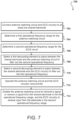
- FIG. 7 illustrates an example process 700 for implementing and utilizing a shared conductive element that can be utilized in accordance with one embodiment. It should be understood for this and other processes discussed herein that there can be additional, alternative, or fewer steps performed in similar or alternative orders, or in parallel, within the scope of the various embodiments unless otherwise stated.
- an antenna matching circuit and ECG circuitry are connected 702 to at least one shared electrode, antenna radiator, or other such conductive element.
- a first operational frequency range is determined 704 for the antenna matching circuit, and a second operational frequency range is determined 706 for the ECG circuit.
- a first decoupling element (or circuitry, etc.) can be selected 708 to be placed between the shared electrode and the antenna matching circuit, in order to filter out the second operational frequency range.
- a second decoupling element (or circuitry, etc.) can be selected 710 to be placed between the shared electrode and the ECG circuit, in order to filter out the first operational frequency range. Taking advantage of these different frequency ranges enables a decoupling circuit, or set of decoupling elements, to be used to pick out the frequency ranges of interest for each circuit, such as where there may be different or other circuits sharing the electrode as well. Once decoupling is in place, the antenna matching circuit and the ECG circuitry can be operated 712 concurrently.
- the antenna matching circuit can then be enabled 714 to transmit a signal and/or receive a signal using the shared electrode in the first operational frequency range, and the ECG circuit can be enabled to receive input from the shared electrode in the second operational frequency range, with minimal cross-talk between the frequency ranges across the decoupling circuitry.
- the ECG circuit can be enabled to receive input from the shared electrode in the second operational frequency range, with minimal cross-talk between the frequency ranges across the decoupling circuitry.
- the various embodiments can be implemented as a system that includes one or more tracking devices for a given user.
- aspects of the embodiments may be provided as a service, which users can utilize for their devices.
- Other tracker providers may also subscribe or utilize such a service for their customers.
- an application programming interface (API) or other such interface may be exposed that enables collected body data, and other information, to be delivered to the service, which can process the information and send the results back down to the tracker, or related computing device, for access by the user.
- API application programming interface
- at least some of the processing may be done on the tracking or computing device itself, but processing by a remote system or service may allow for more robust processing, particularly for tracking devices with limited capacity or processing capability.
- the housing of a device 800 may include a metallic body that forms at least a part of the boundaries of the cavity 862 and a metallic antenna in close proximity to the cavity 862.
- the antenna 852 is located above the metallic body 864.
- a non-metallic material 854 such as a plastic, is illustrated as separating the antenna 852 from the metallic body 864.
- the performance of the antenna may decrease when metallic bodies are positioned within a particular threshold distance or zone from the antenna 852. This may be considered a "keep-out" zone which varies for different antennas.
- the metallic body 864 is positioned and shaped so that it is outside the keep-out zone of the antenna 852.
- the metallic body 864 is described as metallic, in some embodiments this aspect of the housing may not be metallic, but rather a polymer, a plastic, a composite, or other material that can form a portion of the housing with suitable strength and rigidity, for example. It was further discovered that when a metallic body was inserted into the cavity 862 and made contact with the metallic surface of the cavity 862, the inserted metallic body became an electric ground for the metallic body 864 which caused the inserted metallic body to be within the keep-out zone of the antenna 852 and adversely affected the performance of the antenna 852.
- some embodiments of the band latch mechanism disclosed herein are intended to be inserted into the cavity to enable a wristband to be connected to the housing without having a metallic body contact the metallic surfaces of the cavity while still maintaining an adequate connection to the housing and having sufficient robustness, resilience, and strength. Additional detail regarding such an implementation can be found in co-pending U.S. patent application 15/820,928, filed November 22, 2017 , and entitled "Band Latch Mechanism and Housing with Integrated Antenna,” which is hereby incorporated herein in its entirety and for all purposes.
- FIG. 9 illustrates components of an example cycle prediction system 900 that can be utilized in accordance with various embodiments.
- the device includes at least one processor 902, such as a central processing unit (CPU) or graphics processing unit (GPU) for executing instructions that can be stored in a memory device 904, such as may include flash memory or DRAM, among other such options.
- processor 902 such as a central processing unit (CPU) or graphics processing unit (GPU) for executing instructions that can be stored in a memory device 904, such as may include flash memory or DRAM, among other such options.
- the device can include many types of memory, data storage, or computer-readable media, such as data storage for program instructions for execution by a processor. The same or separate storage can be used for images or data, a removable memory can be available for sharing information with other devices, and any number of communication approaches can be available for sharing with other devices.
- the device typically will include some type of display 906, such as a touch screen, organic light emitting diode (OLED) display, or liquid crystal display (
- a tracker or similar device will include at least one motion detection sensor, which as illustrated can include at least one I/O element 910 of the device.
- a sensor can determine and/or detect orientation and/or movement of the device.
- Such an element can include, for example, an accelerometer, inertial sensor, altimeter, or gyroscope operable to detect movement (e.g., rotational movement, angular displacement, tilt, position, orientation, motion along a non-linear path, etc.) of the device.
- An orientation determining element can also include an electronic or digital compass, which can indicate a direction (e.g., north or south) in which the device is determined to be pointing (e.g., with respect to a primary axis or other such aspect).
- a device may also include an I/O element 910 for determining a location of the device (or the user of the device).
- a positioning element can include or comprise a GPS or similar location-determining element(s) operable to determine relative coordinates for a position of the device.
- Positioning elements may include wireless access points, base stations, etc., that may either broadcast location information or enable triangulation of signals to determine the location of the device.
- Other positioning elements may include QR codes, barcodes, RFID tags, NFC tags, etc., that enable the device to detect and receive location information or identifiers that enable the device to obtain the location information (e.g., by mapping the identifiers to a corresponding location).
- Various embodiments can include one or more such elements in any appropriate combination.
- the I/O elements may also include one or more biometric sensors, optical sensors, barometric sensors (e.g., altimeter, etc.), and the like.
- some embodiments use the element(s) to track the location and/or motion of a user.
- the device of some embodiments may keep track of the location of the device by using the element(s), or in some instances, by using the orientation determining element(s) as mentioned above, or a combination thereof.
- the algorithms or mechanisms used for determining a position and/or orientation can depend at least in part upon the selection of elements available to the device.
- the example device also includes one or more wireless components 912 operable to communicate with one or more electronic devices within a communication range of the particular wireless channel.
- the wireless channel can be any appropriate channel used to enable devices to communicate wirelessly, such as Bluetooth, cellular, NFC, or Wi-Fi channels. It should be understood that the device can have one or more conventional wired communications connections as known in the art.
- the device also includes one or more power components 908, such as may include a battery operable to be recharged through conventional plug-in approaches, or through other approaches such as inductive or wireless charging through proximity with a power mat or other such device.
- the device can include at least one additional input/output device 910 able to receive conventional input from a user.
- This conventional input can include, for example, a push button, touch pad, touch screen, wheel, joystick, keyboard, mouse, keypad, or any other such device or element whereby a user can input a command to the device.
- I/O devices could even be connected by a wireless infrared or Bluetooth or other link as well in some embodiments.
- Some devices also can include a microphone or other audio capture element that accepts voice or other audio commands.
- a device might not include any buttons at all, but might be controlled only through a combination of visual and audio commands, such that a user can control the device without having to be in contact with the device.
- many embodiments will include at least some combination of one or more emitters 916 and one or more detectors 918 for measuring data for one or more metrics of a human body, such as for a person wearing the tracker device.
- this may involve at least one imaging element, such as one or more cameras that are able to capture images of the surrounding environment and that are able to image a user, people, or objects in the vicinity of the device.
- the image capture element can include any appropriate technology, such as a CCD image capture element having a sufficient resolution, focal range, and viewable area to capture an image of the user when the user is operating the device. Methods for capturing images using a camera element with a computing device are well known in the art and will not be discussed herein in detail.
- image capture can be performed using a single image, multiple images, periodic imaging, continuous image capturing, image streaming, etc.
- a device can include the ability to start and/or stop image capture, such as when receiving a command from a user, application, or other device.
- the example device includes emitters 916 and detectors 918 capable of being used for obtaining other biometric data, which can be used with example circuitry discussed herein.
- a display 906 may provide an interface for displaying data, such as heart rate (HR), ECG data, blood oxygen saturation (SpO 2 ) levels, and other metrics of the user.
- the device includes a wristband and the display is configured such that the display faces away from the outside of a user's wrist when the user wears the device.
- the display may be omitted and data detected by the device may be transmitted using the wireless networking interface via near-field communication (NFC), Bluetooth, Wi-Fi, or other suitable wireless communication protocols over at least one network 920 to a host computer 922 for analysis, display, reporting, or other such use.
- NFC near-field communication
- Wi-Fi Wireless Fidelity
- the memory 904 may comprise RAM, ROM, FLASH memory, or other non-transitory digital data storage, and may include a control program comprising sequences of instructions which, when loaded from the memory and executed using the processor 902, cause the processor 902 to perform the functions that are described herein.
- the emitters 916 and detectors 918 may be coupled to a bus directly or indirectly using driver circuitry by which the processor 902 may drive the light emitters 916 and obtain signals from the light detectors 918.
- the host computer 922 communicates with the wireless networking components 912 via one or more networks 920, which may include one or more local area networks, wide area networks, and/or internet, using any of terrestrial or satellite links. In some embodiments, the host computer 922 executes control programs and/or application programs that are configured to perform some of the functions described herein.
- approaches discussed herein may be performed by one or more of: firmware operating on a monitoring or tracker device or a secondary device, such as a mobile device paired to the monitoring device, a server, host computer, and the like.
- the monitoring device may execute operations relating to generating signals that are uploaded or otherwise communicated to a server that performs operations for removing the motion components and creating a final estimate value for physiological metrics.
- the monitoring device may execute operations relating to generating the monitoring signals and measuring the motion components to produce a final estimate value for physiological metrics local to the monitoring device.
- the final estimate may be uploaded or otherwise communicated to a server such as host computer that performs other operations using the estimate.
- An example monitoring or tracker device can collect one or more types of physiological and/or environmental data from one or more sensor(s) and/or external devices and communicate or relay such information to other devices (e.g., host computer or another server), thus permitting the collected data to be viewed, for example, using a web browser or network-based application.
- a tracker device may perform biometric monitoring via calculating and storing the user's step count using one or more sensor(s).
- the tracker device may transmit data representative of the user's step count to an account on a web service (e.g., www.fitbit.com), computer, mobile phone, and/or health station where the data may be stored, processed, and/or visualized by the user.
- a web service e.g., www.fitbit.com
- the tracker device may measure or calculate other physiological metric(s) in addition to, or in place of, the user's step count.
- physiological metric(s) may include, but are not limited to: energy expenditure, e.g., calorie burn; floors climbed and/or descended; HR; heartbeat waveform; HR variability; HR recovery; respiration, SpO 2 , blood volume, blood glucose, skin moisture and skin pigmentation level, location and/or heading (e.g., via a GPS, global navigation satellite system (GLONASS), or a similar system); elevation; ambulatory speed and/or distance traveled; swimming lap count; swimming stroke type and count detected; bicycle distance and/or speed; blood glucose; skin conduction; skin and/or body temperature; muscle state measured via electromyography; brain activity as measured by electroencephalography; weight; body fat; caloric intake; nutritional intake from food; medication intake; sleep periods (e.g., clock time, sleep phases, sleep quality and/or duration); pH levels; hydration levels; respiration rate; and/or other
- An example tracker or monitoring device may also measure or calculate metrics related to the environment around the user (e.g., with one or more environmental sensor(s)), such as, for example, barometric pressure, weather conditions (e.g., temperature, humidity, pollen count, air quality, rain/snow conditions, wind speed), light exposure (e.g., ambient light, ultra-violet (UV) light exposure, time and/or duration spent in darkness), noise exposure, radiation exposure, and/or magnetic field exposure.
- a tracker device and/or the host computer and/or another server
- a tracker device may calculate the user's stress or relaxation levels based on a combination of HR variability, skin conduction, noise pollution, and/or sleep quality.
- a tracker device may determine the efficacy of a medical intervention, for example, medication, based on a combination of data relating to medication intake, sleep, and/or activity.
- a tracker device may determine the efficacy of an allergy medication based on a combination of data relating to pollen levels, medication intake, sleep and/or activity.
- An example monitoring device may include a computer-readable storage media reader, a communications device (e.g., a modem, a network card (wireless or wired), an infrared communication device) and working memory as described above.
- the computer-readable storage media reader can be connected with, or configured to receive, a computer-readable storage medium representing remote, local, fixed and/or removable storage devices as well as storage media for temporarily and/or more permanently containing, storing, transmitting and retrieving computer-readable information.
- a monitoring system and various devices also typically will include a number of software applications, modules, services or other elements located within at least one working memory device, including an operating system and application programs such as a client application or Web browser. It should be appreciated that alternate embodiments may have numerous variations from that described above. For example, customized hardware might also be used and/or particular elements might be implemented in hardware, software (including portable software, such as applets) or both. Further, connection to other computing devices such as network input/output devices may be employed.
- Storage media and other non-transitory computer readable media for containing code, or portions of code can include any appropriate media known or used in the art, such as but not limited to volatile and non-volatile, removable and non-removable media implemented in any method or technology for storage of information such as computer readable instructions, data structures, program modules or other data, including RAM, ROM, EEPROM, flash memory or other memory technology, CD-ROM, digital versatile disk (DVD) or other optical storage, magnetic cassettes, magnetic tape, magnetic disk storage or other magnetic storage devices or any other medium which can be used to store the desired information and which can be accessed by a system device.
- RAM random access memory
- ROM read only memory
- EEPROM electrically erasable programmable read-only memory
- flash memory electrically erasable programmable read-only memory
- CD-ROM compact disc read-only memory
- DVD digital versatile disk
- magnetic cassettes magnetic tape
- magnetic disk storage magnetic disk storage devices or any other medium which can be used to store the desired information and which can be
Landscapes
- Health & Medical Sciences (AREA)
- Life Sciences & Earth Sciences (AREA)
- Engineering & Computer Science (AREA)
- Physics & Mathematics (AREA)
- Molecular Biology (AREA)
- General Health & Medical Sciences (AREA)
- Biophysics (AREA)
- Biomedical Technology (AREA)
- Heart & Thoracic Surgery (AREA)
- Medical Informatics (AREA)
- Veterinary Medicine (AREA)
- Surgery (AREA)
- Animal Behavior & Ethology (AREA)
- Pathology (AREA)
- Public Health (AREA)
- Cardiology (AREA)
- Computer Networks & Wireless Communication (AREA)
- Physiology (AREA)
- Electromagnetism (AREA)
- Details Of Aerials (AREA)
- Support Of Aerials (AREA)
- Measurement And Recording Of Electrical Phenomena And Electrical Characteristics Of The Living Body (AREA)
- Variable-Direction Aerials And Aerial Arrays (AREA)
Applications Claiming Priority (3)
| Application Number | Priority Date | Filing Date | Title |
|---|---|---|---|
| US201862697844P | 2018-07-13 | 2018-07-13 | |
| EP19834753.6A EP3821499B1 (de) | 2018-07-13 | 2019-06-28 | Integrierte ekg-elektrode und antennenstrahler |
| PCT/US2019/039975 WO2020014020A1 (en) | 2018-07-13 | 2019-06-28 | Integrated ecg electrode and antenna radiator |
Related Parent Applications (1)
| Application Number | Title | Priority Date | Filing Date |
|---|---|---|---|
| EP19834753.6A Division EP3821499B1 (de) | 2018-07-13 | 2019-06-28 | Integrierte ekg-elektrode und antennenstrahler |
Publications (2)
| Publication Number | Publication Date |
|---|---|
| EP4432468A2 true EP4432468A2 (de) | 2024-09-18 |
| EP4432468A3 EP4432468A3 (de) | 2024-10-02 |
Family
ID=69138148
Family Applications (3)
| Application Number | Title | Priority Date | Filing Date |
|---|---|---|---|
| EP24192699.7A Pending EP4432467A3 (de) | 2018-07-13 | 2019-06-28 | Integrierte ekg-elektrode und antennenstrahler |
| EP19834753.6A Active EP3821499B1 (de) | 2018-07-13 | 2019-06-28 | Integrierte ekg-elektrode und antennenstrahler |
| EP24192702.9A Pending EP4432468A3 (de) | 2018-07-13 | 2019-06-28 | Integrierte ekg-elektrode und antennenstrahler |
Family Applications Before (2)
| Application Number | Title | Priority Date | Filing Date |
|---|---|---|---|
| EP24192699.7A Pending EP4432467A3 (de) | 2018-07-13 | 2019-06-28 | Integrierte ekg-elektrode und antennenstrahler |
| EP19834753.6A Active EP3821499B1 (de) | 2018-07-13 | 2019-06-28 | Integrierte ekg-elektrode und antennenstrahler |
Country Status (5)
| Country | Link |
|---|---|
| US (3) | US10806362B2 (de) |
| EP (3) | EP4432467A3 (de) |
| CN (1) | CN212968034U (de) |
| DE (1) | DE212019000264U1 (de) |
| WO (1) | WO2020014020A1 (de) |
Families Citing this family (16)
| Publication number | Priority date | Publication date | Assignee | Title |
|---|---|---|---|---|
| GB2591434B (en) | 2019-10-29 | 2022-04-20 | Prevayl Innovations Ltd | Wearable article, textile article and method |
| CN113064498B (zh) * | 2020-01-02 | 2023-08-22 | 华为技术有限公司 | 具有天线的触控笔 |
| GB2593949B (en) | 2020-01-21 | 2023-04-26 | Prevayl Innovations Ltd | Electronics module for a wearable article |
| GB2585728B (en) * | 2020-01-21 | 2021-08-18 | Prevayl Ltd | Electronics module for a wearable article |
| US11511177B2 (en) * | 2020-07-06 | 2022-11-29 | Z Enterprises | Pool lap counter |
| KR102928258B1 (ko) * | 2020-08-31 | 2026-02-19 | 삼성전자주식회사 | 생체 신호를 측정 가능한 전자 장치 |
| US12484151B2 (en) | 2020-09-07 | 2025-11-25 | Goertek Technology Co., Ltd. | Electronic device |
| US11128335B1 (en) * | 2020-12-18 | 2021-09-21 | Lifeline SRL | Wrist-wearable satellite communication device |
| EP4266492A4 (de) * | 2021-03-16 | 2024-07-17 | Samsung Electronics Co., Ltd. | Elektronische vorrichtung und verfahren zur verbesserung der antennenleistung einer elektronischen vorrichtung |
| WO2022216093A1 (ko) * | 2021-04-07 | 2022-10-13 | 삼성전자 주식회사 | 안테나를 포함하는 웨어러블 전자 장치 |
| CN117616632A (zh) * | 2021-08-20 | 2024-02-27 | 飞比特有限公司 | 具有多频带缝隙天线和接地寄生元件的可穿戴计算设备 |
| US20250004425A1 (en) * | 2021-10-07 | 2025-01-02 | Fitbit Llc | Wearable computing device having a biometric sensor electrode positioned on a display screen cover and operable as an antenna |
| KR20230082839A (ko) * | 2021-12-02 | 2023-06-09 | 삼성전자주식회사 | 방사체를 포함하는 전자 장치 |
| CN114284704B (zh) * | 2021-12-30 | 2024-12-20 | 上海鸿晔电子科技股份有限公司 | 超宽带天线和通信系统 |
| CN119213630A (zh) * | 2022-06-16 | 2024-12-27 | 谷歌有限责任公司 | 具有集成天线的生物特征传感器组件 |
| US20250219669A1 (en) * | 2023-12-29 | 2025-07-03 | Google Llc | Computing Device Having Sensor with Integrated Antenna |
Family Cites Families (12)
| Publication number | Priority date | Publication date | Assignee | Title |
|---|---|---|---|---|
| JP4588858B2 (ja) | 2000-10-20 | 2010-12-01 | フクダ電子株式会社 | 生体信号ケーブル及び生体信号処理装置 |
| US6647286B1 (en) | 2001-03-02 | 2003-11-11 | Ge Medical Systems Information Technologies, Inc. | Lead and leadset designs for providing medical telemetry antenna |
| US20050027204A1 (en) * | 2003-06-26 | 2005-02-03 | Kligfield Paul D. | ECG diagnostic system and method |
| JP2009296483A (ja) * | 2008-06-09 | 2009-12-17 | Alps Electric Co Ltd | アンテナ装置 |
| US8301232B2 (en) | 2010-06-08 | 2012-10-30 | Alivecor, Inc. | Wireless, ultrasonic personal health monitoring system |
| US8509882B2 (en) | 2010-06-08 | 2013-08-13 | Alivecor, Inc. | Heart monitoring system usable with a smartphone or computer |
| KR101801117B1 (ko) | 2011-07-27 | 2017-11-27 | 삼성전자주식회사 | 휴대용 무선 단말기에서 안테나와 센서용 부재로 병행하는 금속체 및 이와 연동하는 장치 |
| US9722303B2 (en) * | 2013-10-01 | 2017-08-01 | Asustek Computer Inc. | Wearable electronic device |
| TWM493362U (zh) | 2014-08-26 | 2015-01-11 | 華碩電腦股份有限公司 | 穿戴式電子裝置 |
| US9808632B2 (en) | 2015-01-23 | 2017-11-07 | Medtronic, Inc. | Implantable medical device with dual-use communication module |
| CN204971247U (zh) * | 2015-08-21 | 2016-01-20 | 歌尔声学股份有限公司 | 一种智能终端和一种智能腕表 |
| US11688930B2 (en) * | 2018-05-08 | 2023-06-27 | Huawei Technologies Co., Ltd. | Antenna apparatus and mobile terminal |
-
2019
- 2019-06-28 EP EP24192699.7A patent/EP4432467A3/de active Pending
- 2019-06-28 EP EP19834753.6A patent/EP3821499B1/de active Active
- 2019-06-28 CN CN201990000492.0U patent/CN212968034U/zh active Active
- 2019-06-28 EP EP24192702.9A patent/EP4432468A3/de active Pending
- 2019-06-28 WO PCT/US2019/039975 patent/WO2020014020A1/en not_active Ceased
- 2019-06-28 DE DE212019000264.1U patent/DE212019000264U1/de active Active
- 2019-06-28 US US16/457,337 patent/US10806362B2/en active Active
-
2020
- 2020-10-16 US US17/072,561 patent/US11504043B2/en active Active
-
2022
- 2022-11-21 US US17/991,458 patent/US11950914B2/en active Active
Also Published As
| Publication number | Publication date |
|---|---|
| US20210137439A1 (en) | 2021-05-13 |
| US11950914B2 (en) | 2024-04-09 |
| US10806362B2 (en) | 2020-10-20 |
| US20230157610A1 (en) | 2023-05-25 |
| EP4432467A3 (de) | 2024-09-25 |
| EP3821499B1 (de) | 2024-08-07 |
| DE212019000264U1 (de) | 2021-01-28 |
| EP3821499A1 (de) | 2021-05-19 |
| EP3821499A4 (de) | 2022-04-20 |
| EP4432468A3 (de) | 2024-10-02 |
| US20200015701A1 (en) | 2020-01-16 |
| WO2020014020A1 (en) | 2020-01-16 |
| US11504043B2 (en) | 2022-11-22 |
| CN212968034U (zh) | 2021-04-13 |
| EP4432467A2 (de) | 2024-09-18 |
Similar Documents
| Publication | Publication Date | Title |
|---|---|---|
| US11950914B2 (en) | Integrated ECG electrode and antenna radiator | |
| US10892565B2 (en) | Multiple band antenna structures | |
| US11482773B2 (en) | Multiple band antenna structures | |
| US9498129B2 (en) | Method and device for patient monitoring using dynamic multi-function device | |
| US9734315B2 (en) | Wearable terminal | |
| US10367927B2 (en) | Wearable device with an antenna system | |
| US10238288B2 (en) | Direct frequency modulating radio-frequency sensors | |
| US11540136B2 (en) | Device pairing | |
| US20260025211A1 (en) | Network physical layer configurations for ambulatory physiological parameter monitoring and therapeutic intervention systems | |
| AU2015230143B2 (en) | Method of providing antenna by using component in electronic device and the electronic device therefor | |
| US9282909B2 (en) | Measurement device with electroencephalography and electrocardiography functionalities | |
| CN113925481A (zh) | 测量生理信号方法及生理信号测量装置 |
Legal Events
| Date | Code | Title | Description |
|---|---|---|---|
| PUAI | Public reference made under article 153(3) epc to a published international application that has entered the european phase |
Free format text: ORIGINAL CODE: 0009012 |
|
| STAA | Information on the status of an ep patent application or granted ep patent |
Free format text: STATUS: THE APPLICATION HAS BEEN PUBLISHED |
|
| REG | Reference to a national code |
Ref country code: DE Ref legal event code: R079 Free format text: PREVIOUS MAIN CLASS: H01Q0005378000 Ipc: H01Q0001270000 |
|
| PUAL | Search report despatched |
Free format text: ORIGINAL CODE: 0009013 |
|
| AC | Divisional application: reference to earlier application |
Ref document number: 3821499 Country of ref document: EP Kind code of ref document: P |
|
| AK | Designated contracting states |
Kind code of ref document: A2 Designated state(s): AL AT BE BG CH CY CZ DE DK EE ES FI FR GB GR HR HU IE IS IT LI LT LU LV MC MK MT NL NO PL PT RO RS SE SI SK SM TR |
|
| AK | Designated contracting states |
Kind code of ref document: A3 Designated state(s): AL AT BE BG CH CY CZ DE DK EE ES FI FR GB GR HR HU IE IS IT LI LT LU LV MC MK MT NL NO PL PT RO RS SE SI SK SM TR |
|
| RIC1 | Information provided on ipc code assigned before grant |
Ipc: H01Q 5/378 20150101ALI20240829BHEP Ipc: H01Q 7/00 20060101ALI20240829BHEP Ipc: H01Q 1/44 20060101ALI20240829BHEP Ipc: H01Q 13/10 20060101ALI20240829BHEP Ipc: H01Q 1/52 20060101ALI20240829BHEP Ipc: A61B 5/332 20210101ALI20240829BHEP Ipc: A61B 5/00 20060101ALI20240829BHEP Ipc: H01Q 1/24 20060101ALI20240829BHEP Ipc: H01Q 9/04 20060101ALI20240829BHEP Ipc: H01Q 1/27 20060101AFI20240829BHEP |
|
| STAA | Information on the status of an ep patent application or granted ep patent |
Free format text: STATUS: REQUEST FOR EXAMINATION WAS MADE |
|
| 17P | Request for examination filed |
Effective date: 20250319 |
|
| STAA | Information on the status of an ep patent application or granted ep patent |
Free format text: STATUS: EXAMINATION IS IN PROGRESS |
|
| 17Q | First examination report despatched |
Effective date: 20260210 |