EP4432470A1 - Système d'antenne pour cycle d'ordinateur de bicyclette électronique intelligente - Google Patents
Système d'antenne pour cycle d'ordinateur de bicyclette électronique intelligente Download PDFInfo
- Publication number
- EP4432470A1 EP4432470A1 EP23162677.1A EP23162677A EP4432470A1 EP 4432470 A1 EP4432470 A1 EP 4432470A1 EP 23162677 A EP23162677 A EP 23162677A EP 4432470 A1 EP4432470 A1 EP 4432470A1
- Authority
- EP
- European Patent Office
- Prior art keywords
- antenna
- foster
- cycling computer
- bicycle
- metallic
- Prior art date
- Legal status (The legal status is an assumption and is not a legal conclusion. Google has not performed a legal analysis and makes no representation as to the accuracy of the status listed.)
- Pending
Links
Images




Classifications
-
- H—ELECTRICITY
- H01—ELECTRIC ELEMENTS
- H01Q—ANTENNAS, i.e. RADIO AERIALS
- H01Q25/00—Antennas or antenna systems providing at least two radiating patterns
- H01Q25/004—Antennas or antenna systems providing at least two radiating patterns providing two or four symmetrical beams for Janus application
-
- H—ELECTRICITY
- H01—ELECTRIC ELEMENTS
- H01Q—ANTENNAS, i.e. RADIO AERIALS
- H01Q21/00—Antenna arrays or systems
- H01Q21/29—Combinations of different interacting antenna units for giving a desired directional characteristic
- H01Q21/293—Combinations of different interacting antenna units for giving a desired directional characteristic one unit or more being an array of identical aerial elements
-
- H—ELECTRICITY
- H01—ELECTRIC ELEMENTS
- H01Q—ANTENNAS, i.e. RADIO AERIALS
- H01Q9/00—Electrically-short antennas having dimensions not more than twice the operating wavelength and consisting of conductive active radiating elements
- H01Q9/04—Resonant antennas
- H01Q9/16—Resonant antennas with feed intermediate between the extremities of the antenna, e.g. centre-fed dipole
- H01Q9/28—Conical, cylindrical, cage, strip, gauze, or like elements having an extended radiating surface; Elements comprising two conical surfaces having collinear axes and adjacent apices and fed by two-conductor transmission lines
-
- H—ELECTRICITY
- H01—ELECTRIC ELEMENTS
- H01Q—ANTENNAS, i.e. RADIO AERIALS
- H01Q1/00—Details of, or arrangements associated with, antennas
- H01Q1/12—Supports; Mounting means
- H01Q1/22—Supports; Mounting means by structural association with other equipment or articles
- H01Q1/2258—Supports; Mounting means by structural association with other equipment or articles used with computer equipment
-
- H—ELECTRICITY
- H01—ELECTRIC ELEMENTS
- H01Q—ANTENNAS, i.e. RADIO AERIALS
- H01Q1/00—Details of, or arrangements associated with, antennas
- H01Q1/12—Supports; Mounting means
- H01Q1/22—Supports; Mounting means by structural association with other equipment or articles
- H01Q1/2291—Supports; Mounting means by structural association with other equipment or articles used in Bluetooth® or Wi-Fi® devices of Wireless Local Area Networks [WLAN]
-
- H—ELECTRICITY
- H01—ELECTRIC ELEMENTS
- H01Q—ANTENNAS, i.e. RADIO AERIALS
- H01Q1/00—Details of, or arrangements associated with, antennas
- H01Q1/27—Adaptation for use in or on movable bodies
- H01Q1/32—Adaptation for use in or on road or rail vehicles
- H01Q1/325—Adaptation for use in or on road or rail vehicles characterised by the location of the antenna on the vehicle
Definitions
- the Internet of Things is a system of devices connected to the network providing integration between a user and the end product.
- IoT Intelligent Transport System
- ITS Intelligent Transport System
- vehicles are integrated with the user and can communicate either with each other or with their environment.
- This approach offers additional features such as monitoring the user's health, enhanced collision detection and avoidance, and energy-efficient transportation.
- Bicycles as one of the most popular and sustainable means of transportation, can benefit greatly from ITS technology. This is especially true for the so-called e-bicycle.
- the e-bicycle is an electric (or even mechanical) bicycle 100 (shown in FIG. 1 ) equipped with a 'cycling computer' 110, usually mounted under the top tube 130 of a bicycle frame.
- a cycling computer 110 collects raw electrical signals from various sensors (e.g., speed sensor, accelerometer, temperature sensor, camera, etc%) mounted at various locations on the e-bicycle 100.
- the cycling computer 110 may exchange data with the rider's cell phone 120, which is located on the handlebars, via a wireless connection.
- the e-bicycle 100 may also collect various types of navigation data from satellite navigation systems (such as, but not limited to GPS or GLONAS) 160. Cycling computer 110 processes the collected raw sensors signals and provides output information in the form of mileage, speed data, navigation data, physiological parameters of the rider such as heart rate, respiratory rate, etc.
- cycling computer 110 may be mounted behind the saddle of the rider, in the upper tube of the bicycle frame or at any other location on the bicycle 100.
- Processing in a cycling computer 110 produces a large amount of data that is constantly exchanged with some remote computing facilities 180 via cellular networks 140 and 150, such as, but not limited to GSM, UMTS, LTE, or via Wi-Fi hot-spot 170.
- the processed data may be stored in the remote computing facilities 180, or all or part of the processed data may be sent back to cycling computer 110 to be used by the rider.
- Such a smart e-bicycle 100 (or plurality of them), together with the remote computing facilities 180 and associated navigation and communication systems 300, form the cycling-dedicated ITS.
- the internal organization of the cycling computer 110 is shown schematically in FIG. 2 . It comprises a main processing module 205 that receives commands from the user interface module (e.g., keyboard with display or user's cell phone 210) and acquires raw data from the plurality of different sensors 215 mounted at various locations on the bicycle. The processed data are further sent to the radiofrequency (RF) module 220, which comprises one or more radiofrequency transmitters and receivers. In the transmit mode, the data are transmitted in the form of electromagnetic waves via the antenna module 230. It comprises a plurality of antennas and associated feeding networks constructed using inductors and capacitors or segments of transmission lines, as is well known in the art of radio engineering.
- RF radiofrequency
- the antennas in the antenna module 230 can also receive signals from remote computing facilities via cellular networks such as GSM, UMTS, LTE, the Wi-Fi network, or navigation signals from satellite systems such as GNSS. These signals are further processed by the receivers located in the RF module 220, sent to the main processing module 205, and displayed on the user interface module 205.
- cellular networks such as GSM, UMTS, LTE, the Wi-Fi network, or navigation signals from satellite systems such as GNSS.
- the design and fabrication of the antenna system in antenna module 230 is a very challenging engineering task for several reasons.
- broadband passive matching of a small antenna is very difficult.
- the typical fractional bandwidth, defined as the useful bandwidth divided by the center frequency, that can be achieved with passive matching of a small antenna is between 10 and 15%.
- PCB 360 serves as a common ground plane for three different antennas 340, 350, and 370 operating in three different frequency bands. Since the mutual spacing between the antennas is less than one wavelength, the unwanted mutual impedance can be significant. In addition, the size of the ground plane 360 is smaller than the optimal size due to the small space available. Therefore, this small ground plane becomes part of the radiating system, which may also be unintentionally EM coupled to the bicycle frame, degrading the radiation characteristics.
- a bicycle is a dynamic environment that changes its position with respect to the base stations (GSM, UMTS).
- GSM base stations
- UMTS base stations
- the rider's body is in constant motion, which (together with other parts of the bicycle) can cause shadowing of the wireless signal path (so-called 'EM blocking' effect).
- This effect has serious implications for the radiation pattern, path loss and self-impedance, as well as the mutual impedance of the connected antennas.
- the shadowing problem in a realistic blocking scenario 500 is briefly explained in FIG. 4 .
- the cycling computer 410 utilizes wireless communication with various remote navigation and computing systems, either directly or indirectly via the user's cell phone 420.
- the remote systems may be (but are not limited to) satellite navigation systems such as GNSS (460), base stations of various cellular networks such as UMTS (440), LTE (450), or Wi-Fi hotspots (470).
- GNSS GNSS
- UMTS UMTS
- 450 LTE
- 470 Wi-Fi hotspots
- the body of the rider 425 acts as an unwanted "obstacle' that 'blocks' the EM radiation coming from the external systems 460, 440, 450, 470, thus degrading the accuracy of the signal received by the radio module of the cycling computer 410.
- the rider's body also 'blocks" the EM radiation in the opposite direction when the cycling computer 410 is in transmit mode communicating with the external systems 440, 450, 460, 470.
- the phenomenon of blocking is closely related to the radiation pattern of the antennas used, as shown in FIG. 5A . Shown is an 'e-bicycle' with a cycling computer 510 whose antenna system has a main radiation lobe 515 directed upward.
- FIG. 5B The blocking scenario with a rider is shown in FIG 5B .
- a cycling computer 510 mounted to the bicycle frame 512 and a rider 520 are shown essentially 'blocking' the main beam 525.
- the overall size of the antenna is less than one wavelength and the antenna fits into a small space available in typical cycling computer (typically a few cm3), ii) the antenna is less sensitive to the presence of nearby obstacles, such as bicycle frame and rider's body, than existing solutions ii) the antenna has a higher overall efficiency than existing solutions.
- the present disclosure addresses the design that overcomes the aforementioned drawbacks and provides reliable communication of an 'e-bicycle' with remote facilities.
- This application discloses three improvements of the multi-band antennas for a cycling computer of a 'e-bicycle'. Firstly, it mitigates a problem of wireless path blocking by rider's body shown in FIG.4 , FIG.5 (prior art), using specially designed two-antenna array ( FIG. 6 ), for each frequency band of interest. The use of dedicated antenna array also increases realized gain and improves a system back-off factor. Secondly, this patent application introduces a segmented ground-plane of a cycling computer ( FIG. 10 , FIG. 11 ), loaded with 'negative elements', that performs as an antenna. Inclusion of 'negative elements' enables use of a ground plane, dimensions of which are significantly smaller than those used in previous art ( FIG. 8 .
- the third improvement is an active magnetoelectric antenna that comprises a subwavelength metallic plate with a very shallow trench (down to one hundredth of a wavelength), bridged by a negative non-Foster inductor ( FIG. 15A ).
- This ultra-low-profile antenna has a directive cardioid-like radiation with a bandwidth of up to 1:1.3.
- FIGS. 6A, 6B, 6C , 7A and 7B One embodiment that provides a significant mitigation of EM blocking by rider's body is explained with the help of FIGS. 6A, 6B, 6C , 7A and 7B .
- FIG. 6A shows a non-limiting example of dedicated two-element antenna array utilizing inventive concepts presented in this application.
- Two-element antenna array 600 comprises a first antenna 620, a second antenna 630, antenna matching network 640 disposed between them, and external transmitter/receiver 650.
- Said antenna matching network 640 comprises three input/output ports 685, 680, and 690.
- the first antenna 620 is electrically coupled to the first input/output port 690 of said matching network 640 via an electrical connection 660.
- the second antenna 630 is electrically coupled to the second input/output port 680 using an electrical connection 675.
- the third input/output port 685 of the matching network 640 is connected to external transmitter/receiver 650 using an electrical connection 670.
- the electrical connections 660, 675, and 685 may include two electrical conductors, as in a coaxial cable, or may use a microstrip line or a strip line, as is well known in the art of radiofrequency systems.
- matching network 640 does splitting of the transmitting signal generated by transmitter/receiver 650 into two signals with appropriate magnitudes and phases, present at the input/output ports 680 and 690 and subsequently fed to the antennas 630 and 620, via electrical connections 675 and 660.
- the EM radiation from the antennas 620 and 630 forms a radiation pattern with two main lobes, as it is explained in detail in FIGS. 7A and 7B .
- matching network 640 does adjustment of the amplitudes and phases of the signals received by antennas 620 and 630 and combine said signals into the output signal present at the input/output port 685.
- the combined signal presented at the input/output port 685 is further sent to the transmitter/receiver 650, via electrical connection 670.
- the PCB layout of said dedicated two-antenna array is illustrated in Figure 6B . It depicts the cycling computer PCB 610 that acts as a common ground-plane of antennas 620 and 630.
- the antennas 620 and 630 are located at the upper corners of the PCB 610, forming dedicated two-element antenna array 600.
- the side-view of dedicated two-element antenna array 600 is shown in FIG. 6c .
- the antennas 620 and 630 are mounted at the angle of 45 degrees in respect to the PCB surface, assuring inclination of two main antenna radiation lobes.
- FIG. 7A The operation of dedicated two-element antenna array, in the scenario without bicycle rider, is shown in FIG. 7A . It depicts the cycling computer with dedicated antenna array 720, mounted on the bicycle frame 710, together with radiation pattern 730. Due to the operation of matching network (previously explained in Fig 6A ) and the placement of the antennas (previously explained in FIGS. 6B and 6C ), the main lobes point aside from the bicycle, at the angle of 45 degrees in respect to a vertical symmetry line of the bicycle 740. Such orientation of the main beams decreases EM blocking by rider's body, increases antenna gain up to 3 dB, and, therefore, increases the system back-off factor.
- 'antenna booster' which uses a ground plane of some radiofrequency device such as a cell phone, as an antenna
- some radiofrequency device such as a cell phone
- EP2319122A2 European patent EP2319122A2
- J. Anguera A. Andujar, G. Mestre, J. Rahola, and J. Juntunen
- Basic principle of so-called 'antenna booster is illustrated in FIG. 8 ).
- the 'antenna booster' 820 excites one or several characteristic modes of a ground plane 810, and, therefore, enables radiation at one or several frequencies. This way, the 'antenna booster', along with PCB ground plane, make a radiator that is electrically larger and, thus more efficient.
- the matching of such 'antenna system' is achieved by dedicated circuitry ( FIG. 9 ). It comprises an RF transmitter 940 connected to 'antenna booster' 920, via passive matching network 950.
- 'antenna booster' 920 is capacitively (or inductively) coupled to a wireless device ground plane 910.
- passive network 950 By appropriate choice of reactive elements in passive network 950, it is possible to excite desired characteristic mode and assure efficient radiation (the design of matching network is also described in detail in US patent US8203492B2 , European patent EP2319122A2 , and in review journal article J. Anguera, A. Andujar, G. Mestre, J. Rahola, and J. Juntunen, "Design of multiband antenna systems for wireless devices using antenna boosters [application notes]," IEEE Microwave Magazine, vol. 20, no. 12, pp. 102-114, 2019 ).
- FIG. 10 shows a 'segmented ground plane' that forms radiation system 1020. It comprises a very small antenna 1010 ('antenna booster') connected to transmitter/receiver 1030.
- the 'antenna booster' 1010 is capacitively (or inductively) coupled to the cycling computer ground plane, which is cut into three different segments 1005, 1006, and 1007.
- the segments are mutually connected via networks that contain active circuits behaving as negative (so-called non-Foster) reactive elements (negative capacitors and negative inductors) 1008 and 1009.
- active circuits are referred to as non-Foster elements because they do not obey Foster reactance theorem that states that the slope of the reactance or susceptance curve against frequency is positive for every passive network.
- non-Foster elements enable compensation of a frequency dispersion of ordinary reactive network with the 'inverse' dispersion provided by a 'negative' non-Foster network.
- This active compensation yields (theoretically) infinite bandwidth as is well known in the art of radio engineering.
- This property is sometimes used in the antenna technology for broadband matching (for instance, see S. E. Sussman-Fort, R. M. Rudish, "Non-Foster impedance matching of electrically-small Antennas," IEEE Transactions on Antennas and Propagation, pp. 2230-2241, vol 57, Aug 2009 ) and for design of broadband self-oscillating antennas ( S. Hrabar, A. Kiricenko, and I.
- Rojas "Loop-type electrically small antenna loaded with non-foster circuit," in 2014 United States National Committee of URSI National Radio Science Meeting (USNC-URSI NRSM), pp. 1-1, 2014 ., A. M. Elfrgani and R. G. Rojas, "Non-Foster circuit embedded within electrically small antenna,” in 2014 IEEE Antennas and Propagation Society International Symposium (APSURSI), pp. 466-467, 2014 ., L. Batel, J.-F. Pintos, and L. Rudant, "Superdirective and broadband compact antenna array using non-foster elements," in 2019 International Workshop on Antenna Technology (iWAT), pp. 17-20, 2019 ).
- All of aforementioned examples use ordinary, well-known, antennas such as small dipole or loop, but they do not use excited ground plane.
- the inclusion of non-Foster elements 1008 and 1009 are embedded into a segmented ground plane 1020, instead of an ordinary antenna.
- the segmented ground plane is EM coupled to a small primary radiator 1010, connected to the transmitter/receiver 1030.
- the segmentation of ground plane enables resonant excitation of characteristic modes although the overall size of a ground plane can be considerably smaller than a wavelength.
- a ground plane 1160 is segmented in two orthogonal directions that yields four rectangular metallic radiators (1105, 1110, 1120, and 1125), bridged by four non-Foster networks (1130, 1140, 1135, 1150). Since there are two degrees of freedom available for each rectangular radiator (its height and width) it is possible to excite even more characteristic modes (comparing to the embodiment illustrated in FIG. 10 ) (GSM, UMTS, GNSS, and Wi-Fi bands, for instance).
- GSM Global System for Mobile Communications
- FIG. 12 uses the positive and negative circuit elements, shown in FIG. 12 .
- They are: ordinary positive capacitor 1205, ordinary positive inductor 1206, negative non-Foster capacitor 1207, and negative non-Foster inductor 1208.
- These elements are connected in well-known matching and phase shifting circuits such as those discussed in publicity available literature (for instance, see S. Hrabar, "First ten years of active metamaterial structures with "negative” elements," EPJ Applied Metamaterials, vol. 5, no. 9, pp. 1-12, 2018 ., S. Al Mokdad, R. Lababidi, M. Le Roy, S. Sadek, A. Perennec and D.
- the bridging networks in embodiments shown in FIGS. 10 and 11 may also contain a negative resistor 1209 ( FIG. 12 ). Inclusion of the negative resistor 1209 can compensate for losses caused by high current density that can occur for the case of extremely small ground plane segments (significantly smaller than a wavelength of operating signal).
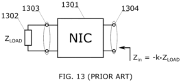
- Negative elements depicted in FIG. 12 can be realized using appropriate electronic circuitry that are generally referred to as “negative impedance converters" (NICs).
- NIC negative impedance converter
- a negative impedance converter (NIC) is a two-port electronic circuit that transforms an ordinary positive load impedance into a negative input impedance, the absolute value of which is substantially equal to the absolute value of the load impedance.
- a load Z LOAD is a capacitor, inductor, or resistor
- the input impedance behaves as a negative capacitance, negative inductance, or negative resistance, respectively.
- the NIC that is stable if its input port is short-circuited is usually designated as the SCS (Short-circuit-stable NIC) or the N type NIC.
- SCS Short-circuit-stable NIC
- OCS Open-circuit-stable NIC
- Huygens antenna is described in many antenna textbooks (for instance, see C. A. Balanis, Antenna Theory: Analysis and Design, 4th ed., Hoboken, NJ: John Wiley & Sons, 2016 ). The brief explanation of operation of basic Huygens antenna is summarized in FIG. 14A .
- a superposition of the fields radiated by an electric dipole (associated with electric current density J) and magnetic dipole (associated with magnetic current density M) forms a cardioid directive pattern 1405 in the x-z plane. Due to the duality, a superposition of the fields radiated by electric dipole (associated with electric current density J) and magnetic dipole (associated with magnetic current density M) also forms a cardioid directive pattern 1406 in the y-z plane.
- the directivity of radiation patterns 1405 and 1406 is 4.77 dB.
- a practical implementation of the basic principle from FIG. 14A is usually rather challenging. While a short electric dipole can be easily constructed, there is no simple implementation of a magnetic dipole.
- a classical solution is to use a subwavelength magnetic loop.
- the Huygens antenna which includes a short dipole and a small loop, is attractive because it can have a small footprint and a low profile.
- the drawback is that the loop current must have a phase shift of 90 degrees with respect to the dipole current. This can be achieved by additional lumped capacitor, as described in: P.A. Turalchuk, D. V. Kholodnyak and O. G. Vendik, "A novel low-profile antenna with hemispherical coverage suitable for wireless and mobile communications applications", 2008 Loughborough Antennas and Propagation Conference, 2008, pp. 337-340 .
- Another possibility of achieving a phase shift of 90 degrees is sing the mutual impedance created when the electric dipole is offset from the loop symmetry line, as discussed in: M.
- FIG. 14B Another well-known solution is the so-called magnetoelectric antenna, originally introduced in K. M. Luk and H. Wong, "A new wideband unidirectional antenna element,” Int. J. Microw. Opt. Tech., vol. 1, no. 1, pp. 35-44, Jun. 2006 .
- This antenna is sketched in FIG. 14B . It consists of a square-shaped electric dipole 1412, a magnetic dipole in the form of narrow metallic 'trench' 1413, and a ground-plane reflector 1414. The electric dipole 1412 and the magnetic dipole 1413 are driven simultaneously by a generator (transmitter) 1411.
- a narrow metallic "trench” has a length and depth of /2 and ⁇ /4, respectively ( ⁇ being a signal wavelength).
- the trench 1411 can be thought of as a quarter-wave shorted patch (or a short-circuited quarter-wave transmission line) with infinite input impedance. It is well-known that an infinite impedance is a property of perfect electric conductor (PMC) behavior. Thus, the opening of the trench 1413 supports a longitudinal flow of the equivalent magnetic current and behaves like a magnetic dipole. Due this thoughtful implementation there is no need for additional network for achieving of 90 degrees phase shift between currents that excite electric anda magnetic dipole. In addition, the antenna in FIG. 13b) has a large reflector ( ⁇ ground plane) that further increases directivity. Unfortunately, both the ⁇ /4 height of the 'trench 1413' and the ⁇ ground plane 1414 make overall antenna size too large for mounting in the most of cycling computers.
- FIG. 15A shows the magnetoelectric antenna 1500 having its thickness and footprint reduced to ⁇ /100 and to ⁇ /2 ⁇ ⁇ /2, respectively.
- This antenna can be fitted in the most cycling computers available in the market.
- antenna 1500 comprises of square-shaped electric dipole 1501 and a magnetic dipole in the form of a narrow metallic 'trench' 1505 whose length is equal to ⁇ /2.
- the depth of the 'trench' 1505 is only ⁇ /100.
- the equivalent input impedance of the 'trench' 1505 behaves like an equivalent inductor.
- the inductance of equivalent inductor is nearly independent of frequency across a wide bandwidth (wider than one octave).
- the equivalent inductor is compensated by a negative inductor 1508, the inductance of which is equal to the impedance at the 'trench' opening at points X and Y of the 'trench' 1505, but with opposite sign. Due to compensation, overall impedance at points X and Y of the 'trench' 1505 is infinite across wide frequency bandwidth, causing PMC behavior and supporting a longitudinal flow of the equivalent magnetic current.
- Described compensation is similar to active non-Foster matching well known in the art of antenna engineering (for instance, one may look at S. E. Sussman-Fort, R. M. Rudish, "Non-Foster impedance matching of electrically-small Antennas," IEEE Transactions on Antennas and Propagation, pp. 2230-2241, vol 57, Aug 2009 ).
- the design of the negative inductor 1508, attached to the 'trench' 1505, can be performed using well-known methods from the art of radio electronics.
- One possible implementation is depicted in the embodiment in FIG. 15B . It comprises of the SCS NIC 1511, whose output port 1513 is loaded with ordinary positive inductor 1514.
- the input port 1512 of the NIC 1511 is connected to the points X and Y of the antenna 1500 from FIG. 15A .
- the antenna 1500 can be configured for operation in both transmitting and receiving modes. If the antenna 1500 is operatively configured to work in transmitting mode, the external transmitter 1516 is connected to the input port 1512 of the NIC 1511.
- the receiver 1518 is connected to the input port 1512 of the NIC 1511. It is assumed that the NIC 1511 is designed to be stable in both transmitting mode (when the external transmitter 1516 is connected to the input port 1512) as well as in the receiving mode (when the receiver 1518 is connected to the input port 1512).
- the design of the negative inductor 1508 can also be modified for operation in the self-oscillating mode, as depicted in the embodiment in FIG. 15C .
- This configuration comprises of the SCS NIC 1521, whose output port 1523 is loaded with ordinary positive inductor 1524.
- the inductance of the inductor 1524 is selected to be smaller than the equivalent inductance of the 'trench' 1505 of the antenna 1500.
- the input port of NIC 1511, the input impedance of which behaves as negative inductance, is connected to the points X and Y of the antenna 1500 from FIG. 15A via an external tuning capacitor 1525.
- FIG. 16 and FIG. 17 present an example of simulation results that compare the FTBR and directivity both in the forward (F) and backward (B) directions of the standard magnetoelectric antenna from prior art from FIG. 14B and the non-Foster magnetoelectric antenna, using the present invention ( FIG. 15A ). Both antennas are designed for operation in the 1 GHz band.
- the standard magnetoelectric antenna from prior art from FIG. 14B
- the standard magnetoelectric antenna from prior art from FIG. 14B
- ⁇ ground-plane reflector and ⁇ /4 thickness has the FTBR > 10 dB across the bandwidth of 1:1.5 (0.65 GHz-1 GHz) ( FIG.
- the simulation results of the non-Foster- magneto-electric antenna 1500 from the embodiment in FIG.15A with ⁇ /2 ⁇ /2 footprint and extremely low profile show the FTBR > 10 dB bandwidth of the 1:1.3 (0.75 GHz-1 GHz) ( FIG. 16 ), while the directivity varies between 5.2 dB and 5.7 dB ( FIG. 17 ).
- These values are significantly better than the values of the of standard magnetoelectric antenna from FIG. 14B , with a thickness of ⁇ /4 and a footprint of ⁇ /2 ⁇ /2 without a ground plane.
- additional two-element array with their own feeding networks may be mounted at the lower left and right corners of the PCB in FIG. 6A , following the methodology depicted in FIG. 6C .
- a radio module of a cycling computer would have a multi-band antenna array that generates two-beam radiation pattern similar to the pattern from Fig7A and Fig 7B , which mitigates the EM blocking problem.
- Another modification may be the addition of beam steering features to antenna based on segmented ground plane loaded with non-Foster elements ( FIG. 10 and FIG. 11 ).
- Yet another modification may include automatic impedance matching, achieved by implementation of tunable non-Foster capacitors for segmented ground plane depicted in FIG. 10 and FIG. 11 . This may be achieved by using varactor didoes as inverting load impedances Z LOAD of the NIC 1301 from FIG. 9 . Changing the DC bias of a varactor would change the negative input capacitance of the NIC 1301 from FIG.13 .
- the varactor diode can also be used as a tuning capacitor 1525 ( FIG. 15C ), for the self-oscillating mode of the non-Foster magnetoelectric antenna 1500 ( FIG. 15A ). If a wider tuning range is needed, an additional inductor may also be connected in series with varactor diode. Furthermore, the use of a varactor diode may also allow the implementation of various types of analog and digital modulations, for the application in cycling computers.
Landscapes
- Variable-Direction Aerials And Aerial Arrays (AREA)
Priority Applications (1)
| Application Number | Priority Date | Filing Date | Title |
|---|---|---|---|
| EP23162677.1A EP4432470A1 (fr) | 2023-03-17 | 2023-03-17 | Système d'antenne pour cycle d'ordinateur de bicyclette électronique intelligente |
Applications Claiming Priority (1)
| Application Number | Priority Date | Filing Date | Title |
|---|---|---|---|
| EP23162677.1A EP4432470A1 (fr) | 2023-03-17 | 2023-03-17 | Système d'antenne pour cycle d'ordinateur de bicyclette électronique intelligente |
Publications (1)
| Publication Number | Publication Date |
|---|---|
| EP4432470A1 true EP4432470A1 (fr) | 2024-09-18 |
Family
ID=85704890
Family Applications (1)
| Application Number | Title | Priority Date | Filing Date |
|---|---|---|---|
| EP23162677.1A Pending EP4432470A1 (fr) | 2023-03-17 | 2023-03-17 | Système d'antenne pour cycle d'ordinateur de bicyclette électronique intelligente |
Country Status (1)
| Country | Link |
|---|---|
| EP (1) | EP4432470A1 (fr) |
Citations (4)
| Publication number | Priority date | Publication date | Assignee | Title |
|---|---|---|---|---|
| FR2807876B1 (fr) * | 2000-04-18 | 2002-06-21 | Ct Regional D Innovation Et De | Antenne plaque micro-onde |
| EP2319122A2 (fr) | 2008-08-04 | 2011-05-11 | Fractus S.A. | Dispositif sans fil sans antenne |
| US20140306846A1 (en) * | 2013-04-16 | 2014-10-16 | Nippon Pillar Packing Co., Ltd. | Microstrip Antenna |
| US10461440B2 (en) | 2017-11-15 | 2019-10-29 | University Of Zagreb Faculty Of Electrical Engineering And Computing | Antenna-transmitter array |
-
2023
- 2023-03-17 EP EP23162677.1A patent/EP4432470A1/fr active Pending
Patent Citations (5)
| Publication number | Priority date | Publication date | Assignee | Title |
|---|---|---|---|---|
| FR2807876B1 (fr) * | 2000-04-18 | 2002-06-21 | Ct Regional D Innovation Et De | Antenne plaque micro-onde |
| EP2319122A2 (fr) | 2008-08-04 | 2011-05-11 | Fractus S.A. | Dispositif sans fil sans antenne |
| US8203492B2 (en) | 2008-08-04 | 2012-06-19 | Fractus, S.A. | Antennaless wireless device |
| US20140306846A1 (en) * | 2013-04-16 | 2014-10-16 | Nippon Pillar Packing Co., Ltd. | Microstrip Antenna |
| US10461440B2 (en) | 2017-11-15 | 2019-10-29 | University Of Zagreb Faculty Of Electrical Engineering And Computing | Antenna-transmitter array |
Non-Patent Citations (23)
| Title |
|---|
| A. ELFRGANIR. G. ROJAS: "Loop-type electrically small antenna loaded with non-foster circuit", 2014 UNITED STATES NATIONAL COMMITTEE OF URSI NATIONAL RADIO SCIENCE MEETING (USNC-URSI NRSM, 2014, pages 1 - 1, XP032662609, DOI: 10.1109/USNC-URSI-NRSM.2014.6927986 |
| A. M. ELFRGANIR. G. ROJAS: "Non-Foster circuit embedded within electrically small antenna", 2014 IEEE ANTENNAS AND PROPAGATION SOCIETY INTERNATIONAL SYMPOSIUM (APSURSI, 2014, pages 466 - 467, XP032644916, DOI: 10.1109/APS.2014.6904564 |
| C. A. BALANIS: "Antenna Theory: Analysis and Design", 2016, JOHN WILEY & SONS |
| D. SEGOVIA-VARGASV. GONZALEZ-POSADASJ.L. JIMENEZE. UGARTE- MUNOZJ. HERRAIZ-MARTINEZL.E. GARCIA-MUNOZ: "Negative Impedance Converters (NICs) in the Design of Small and Multifrequency Antennas", PROCEEDINGS OF THE 5TH EUROPEAN CONFERENCE ON ANTENNAS AND PROPAGATION (EUCAP, 2011, pages 2724 - 272 |
| J. ANGUERAA. ANDUJARG. MESTREJ. RAHOLAJ. JUNTUNEN: "Design of multiband antenna systems for wireless devices using antenna boosters [application notes", IEEE MICROWAVE MAGAZINE, vol. 20, no. 12, 2019, pages 102 - 114, XP011754337, DOI: 10.1109/MMM.2019.2941662 |
| J.G. LINVILL: "Transistor Negative Impedance Converters", PROCEEDINGS IRE, vol. 41, June 1953 (1953-06-01), pages 725 - 729, XP011153907 |
| K. M. LUKH. WONG: "A new wideband unidirectional antenna element", INT. J. MICROW. OPT. TECH., vol. 1, no. 1, June 2006 (2006-06-01), pages 35 - 44 |
| L. BATELJ.-F. PINTOSL. RUDANT: "Superdirective and broadband compact antenna array using non- foster elements", 2019 INTERNATIONAL WORKSHOP ON ANTENNA TECHNOLOGY (IWAT, 2019, pages 17 - 20, XP033558426, DOI: 10.1109/IWAT.2019.8730643 |
| L. GEK. M. LUK: "A low-profile magneto-electric dipole antenna", IEEE TRANS. ANT. AND PROP., vol. 60, no. 4, April 2012 (2012-04-01), pages 1684 - 1689 |
| L. VINCELJI. KROISS. HRABAR: "IEEE Transactions on Antennas and Propagation", vol. 68, 2017, IEEE, article "Toward self-oscillating non-Foster unit cell for future active metasurfaces", pages: 1665 - 1679,875-876 |
| LI MINGJIAN ET AL: "Miniaturization of Magnetoelectric Dipole Antenna by Using Metamaterial Loading", IEEE TRANSACTIONS ON ANTENNAS AND PROPAGATION, IEEE, USA, vol. 64, no. 11, 1 November 2016 (2016-11-01), pages 4914 - 4918, XP011627075, ISSN: 0018-926X, [retrieved on 20161028], DOI: 10.1109/TAP.2016.2599176 * |
| M. -C. TANGH. WANGR. W. ZIOLKOWSKI: "Design and Testing of Simple, Electrically Small, Low-Profile, Huygens Source antennas with broadside radiation performance", IEEE TRANS. ON ANT. AND PROP., vol. 64, no. 11, November 2016 (2016-11-01), pages 4607 - 4617, XP011627099, DOI: 10.1109/TAP.2016.2606552 |
| N. LAIH. KIMS. YOON: "A Wideband Active Phase Shifter using Positive and Negative Inductance/Capacitance", IEEE MICROWAVE AND WIRELESS COMPONENTS LETTERS, vol. 26, no. 11, November 2016 (2016-11-01), pages 927 - 929, XP011633356, DOI: 10.1109/LMWC.2016.2615007 |
| P.A. TURALCHUKD. V. KHOLODNYAKO. G. VENDIK: "A novel low-profile antenna with hemispherical coverage suitable for wireless and mobile communications applications", 2008 LOUGHBOROUGH ANTENNAS AND PROPAGATION CONFERENCE, 2008, pages 337 - 340, XP031250021 |
| R. HARRINGTONJ. MAUTZ: "Computation of characteristic modes for conducting bodies", IEEE TRANSACTIONS ON ANTENNAS AND PROPAGATION, vol. 19, September 1971 (1971-09-01), pages 629 - 639, XP055294265, DOI: 10.1109/TAP.1971.1139990 |
| R. HARRINGTONJ. MAUTZ: "Theory of characteristic modes for conducting bodies", IEEE TRANSACTIONS ON ANTENNAS AND PROPAGATION, vol. 19, September 1971 (1971-09-01), pages 622 - 628, XP002459760, DOI: 10.1109/TAP.1971.1139999 |
| S. AL MOKDADR. LABABIDIM. LE ROYS. SADEKA. PERENNECD. LE JEUNE: "Wideband Active Tunable Phase Shifter Using Improved Non-Foster circuit", 2018 25TH IEEE INTERNATIONAL CONFERENCE ON ELECTRONICS, CIRCUITS AND SYSTEMS (ICECS, 2018, pages 449 - 452, XP033504139, DOI: 10.1109/ICECS.2018.8618011 |
| S. E. SUSSMAN-FORTR. M. RUDISH: "Non-Foster impedance matching of electrically-small Antennas", IEEE TRANSACTIONS ON ANTENNAS AND PROPAGATION, vol. 57, August 2009 (2009-08-01), pages 2230 - 2241, XP011269388, DOI: 10.1109/TAP.2009.2024494 |
| S. HRABAR: "First ten years of active metamaterial structures with ''negative'' elements", EPJ APPLIED METAMATERIALS, vol. 5, no. 9, 2018, pages 1 - 12 |
| S. HRABARA. KIRICENKOI. KROIS: "Antenna-transmitter based on non-Foster source", 2017 IEEE INTERNATIONAL SYMPOSIUM ON ANTENNAS, AND PROPAGATION & USNC/URSI NATIONAL RADIO SCIENCE MEETING |
| STEPHEN E. SUSSMAN-FORT: "Gyrator-Based Biquad Filters and Negative Impedance Converters for MicroWaves", INTERNATIONAL JOURNAL OF RF AND MICROWAVE COMPUTER-AIDED ENGINEERING, vol. 8, no. 2, 1998, pages 86 - 101 |
| VINCELJ LEO ET AL: "Dynamical Behavior of Non-Foster Self-oscillating Antenna", 2020 INTERNATIONAL SYMPOSIUM ELMAR, IEEE, 14 September 2020 (2020-09-14), pages 17 - 20, XP033838447, [retrieved on 20201008], DOI: 10.1109/ELMAR49956.2020.9219037 * |
| ZANIC DOMINIK ET AL: "Multi-band Antenna System for Fully Connected Smart E-bicycle", 2021 INTERNATIONAL SYMPOSIUM ELMAR, IEEE, 13 September 2021 (2021-09-13), pages 43 - 48, XP033981231, [retrieved on 20210927], DOI: 10.1109/ELMAR52657.2021.9550900 * |
Similar Documents
| Publication | Publication Date | Title |
|---|---|---|
| US7286094B2 (en) | Three-dimensional omni-directional antenna designs for ultra-wideband applications | |
| US6483463B2 (en) | Diversity antenna system including two planar inverted F antennas | |
| US6828947B2 (en) | Nested cavity embedded loop mode antenna | |
| TW202203507A (zh) | 雙重頻帶橫向極化5g毫米波相位陣列天線 | |
| US9559422B2 (en) | Communication device and method for designing multi-antenna system thereof | |
| WO2004004068A1 (fr) | Dispositif antenne | |
| US7545339B2 (en) | Planar antenna apparatus for ultra wide band applications | |
| WO2005067549A2 (fr) | Structures d'antennes doublets magnetiques multifrequences | |
| CN115149249A (zh) | 高增益微带天线阵列、毫米波车载雷达传感器及车辆 | |
| US20200203803A1 (en) | Antenna element, antenna array and base station | |
| US12062849B2 (en) | Slanted polarization antenna | |
| EP2375488B1 (fr) | Antenne planaire et dispositif portable | |
| EP4528923A1 (fr) | Système d'antenne et dispositif électronique | |
| US10553944B2 (en) | Slot line volumetric antenna | |
| JP5722731B2 (ja) | アンテナ装置 | |
| EP4432470A1 (fr) | Système d'antenne pour cycle d'ordinateur de bicyclette électronique intelligente | |
| US7262741B2 (en) | Ultra wideband antenna | |
| WO2024097557A1 (fr) | Antennes de type pifa/ifa multiples fonctionnant à la même fréquence comprenant des broches courtes pour réduire au minimum la séparation d'antenne | |
| Kannappan et al. | Sub-6 GHz eight-port 3-D vehicular antenna | |
| WO2008056159A1 (fr) | Antenne multifréquences | |
| CN118920089B (zh) | 一种集成超表面的脊波导天线 | |
| CN115706333B (zh) | 可移动装置及其区块式毫米波阵列天线模块 | |
| Rodriguez-Cano et al. | Radiation pattern reconfigurable mm-wave bow-tie array integrated with PIFA antenna | |
| WO2018156829A1 (fr) | Antenne volumétrique à ligne de fente | |
| Al-Mulla | Master Thesis Implementation and optimization of a phased OAM antenna array |
Legal Events
| Date | Code | Title | Description |
|---|---|---|---|
| PUAI | Public reference made under article 153(3) epc to a published international application that has entered the european phase |
Free format text: ORIGINAL CODE: 0009012 |
|
| STAA | Information on the status of an ep patent application or granted ep patent |
Free format text: STATUS: THE APPLICATION HAS BEEN PUBLISHED |
|
| AK | Designated contracting states |
Kind code of ref document: A1 Designated state(s): AL AT BE BG CH CY CZ DE DK EE ES FI FR GB GR HR HU IE IS IT LI LT LU LV MC ME MK MT NL NO PL PT RO RS SE SI SK SM TR |
|
| STAA | Information on the status of an ep patent application or granted ep patent |
Free format text: STATUS: REQUEST FOR EXAMINATION WAS MADE |
|
| 17P | Request for examination filed |
Effective date: 20250114 |
|
| GRAP | Despatch of communication of intention to grant a patent |
Free format text: ORIGINAL CODE: EPIDOSNIGR1 |
|
| STAA | Information on the status of an ep patent application or granted ep patent |
Free format text: STATUS: GRANT OF PATENT IS INTENDED |
|
| RIC1 | Information provided on ipc code assigned before grant |
Ipc: H01Q 9/28 20060101AFI20260323BHEP Ipc: H01Q 21/29 20060101ALI20260323BHEP Ipc: H01Q 25/00 20060101ALI20260323BHEP Ipc: H01Q 1/22 20060101ALN20260323BHEP Ipc: H01Q 1/32 20060101ALN20260323BHEP |