EP4432484A1 - Prise de communication, en particulier prise rj45, utilisation d'une prise de communication et procédé de fabrication d'une prise de communication - Google Patents
Prise de communication, en particulier prise rj45, utilisation d'une prise de communication et procédé de fabrication d'une prise de communication Download PDFInfo
- Publication number
- EP4432484A1 EP4432484A1 EP24163403.9A EP24163403A EP4432484A1 EP 4432484 A1 EP4432484 A1 EP 4432484A1 EP 24163403 A EP24163403 A EP 24163403A EP 4432484 A1 EP4432484 A1 EP 4432484A1
- Authority
- EP
- European Patent Office
- Prior art keywords
- contact
- contact element
- section
- socket
- communication
- Prior art date
- Legal status (The legal status is an assumption and is not a legal conclusion. Google has not performed a legal analysis and makes no representation as to the accuracy of the status listed.)
- Pending
Links
Images



Classifications
-
- H—ELECTRICITY
- H01—ELECTRIC ELEMENTS
- H01R—ELECTRICALLY-CONDUCTIVE CONNECTIONS; STRUCTURAL ASSOCIATIONS OF A PLURALITY OF MUTUALLY-INSULATED ELECTRICAL CONNECTING ELEMENTS; COUPLING DEVICES; CURRENT COLLECTORS
- H01R24/00—Two-part coupling devices, or either of their cooperating parts, characterised by their overall structure
- H01R24/60—Contacts spaced along planar side wall transverse to longitudinal axis of engagement
- H01R24/62—Sliding engagements with one side only, e.g. modular jack coupling devices
- H01R24/64—Sliding engagements with one side only, e.g. modular jack coupling devices for high frequency, e.g. RJ 45
-
- H—ELECTRICITY
- H01—ELECTRIC ELEMENTS
- H01R—ELECTRICALLY-CONDUCTIVE CONNECTIONS; STRUCTURAL ASSOCIATIONS OF A PLURALITY OF MUTUALLY-INSULATED ELECTRICAL CONNECTING ELEMENTS; COUPLING DEVICES; CURRENT COLLECTORS
- H01R13/00—Details of coupling devices of the kinds covered by groups H01R12/70 or H01R24/00 - H01R33/00
- H01R13/646—Details of coupling devices of the kinds covered by groups H01R12/70 or H01R24/00 - H01R33/00 specially adapted for high-frequency, e.g. structures providing an impedance match or phase match
- H01R13/6461—Means for preventing cross-talk
- H01R13/6467—Means for preventing cross-talk by cross-over of signal conductors
-
- H—ELECTRICITY
- H01—ELECTRIC ELEMENTS
- H01R—ELECTRICALLY-CONDUCTIVE CONNECTIONS; STRUCTURAL ASSOCIATIONS OF A PLURALITY OF MUTUALLY-INSULATED ELECTRICAL CONNECTING ELEMENTS; COUPLING DEVICES; CURRENT COLLECTORS
- H01R12/00—Structural associations of a plurality of mutually-insulated electrical connecting elements, specially adapted for printed circuits, e.g. printed circuit boards [PCB], flat or ribbon cables, or like generally planar structures, e.g. terminal strips, terminal blocks; Coupling devices specially adapted for printed circuits, flat or ribbon cables, or like generally planar structures; Terminals specially adapted for contact with, or insertion into, printed circuits, flat or ribbon cables, or like generally planar structures
- H01R12/70—Coupling devices
- H01R12/71—Coupling devices for rigid printing circuits or like structures
- H01R12/72—Coupling devices for rigid printing circuits or like structures coupling with the edge of the rigid printed circuits or like structures
- H01R12/722—Coupling devices for rigid printing circuits or like structures coupling with the edge of the rigid printed circuits or like structures coupling devices mounted on the edge of the printed circuits
- H01R12/724—Coupling devices for rigid printing circuits or like structures coupling with the edge of the rigid printed circuits or like structures coupling devices mounted on the edge of the printed circuits containing contact members forming a right angle
Definitions
- the present invention relates to a communication socket, in particular an RJ45 socket, for receiving a complementary communication plug, in particular an RJ45 plug, the use of a communication socket, and a method for producing a communication socket.
- RJ45 sockets are known in network technology.
- RJ45 sockets form a physical interface for data and/or voltage transmission and have a plurality of contact elements with which one or more electrical signals, for example a data signal or a voltage, can be transmitted.
- the transmission path of the electrical signals, of which the contact elements of the RJ45 socket represent a section can be susceptible to interference and distortions caused by environmental influences and/or other electrical signals.
- an electrical signal that is transmitted via a contact element of the RJ45 socket can be disturbed by another electrical signal that is transmitted via an adjacent contact element.
- the object of the invention is to provide a communication socket in which interference or distortion of a transmitted electrical signal can be reduced or compensated. Furthermore, the object of the invention is to provide a manufacturing method for a communication socket according to the invention, as well as a method for using a communication socket according to the invention.
- the section-wise guiding of the first contact element and the second contact element along the third contact element allows the compensation of distortions that an electrical signal transmitted on the third contact element causes in the first contact element and the second contact element.
- the first contact element pair transmits a differential signal.
- the first contact element pair i.e. the first contact element and the second contact element, can thus be regarded as a differential pair.
- both the first contact element and the second contact element are sectionally adjacent runs next to the third contact element, both the electrical signal on the first contact element and the electrical signal on the second contact element are exposed to the electromagnetic influences of the electrical signal on the third contact element. Distortions of the electrical signal on the first contact element and the electrical signal on the second contact element that result from this can be compensated for due to the transmission as a differential signal.
- the communication socket can be designed to be connected to another device.
- the communication socket can be connected to a circuit board and the second contact section of the contact elements can be connected to corresponding electrical lines of the circuit board.
- the second contact section of the contact elements can be led out of the housing in order to insert the second contact section into provided contact openings or contact holes in the circuit board, whereby electrical contact can be made between the plurality of socket-side contact elements and the electrical lines of the circuit board.
- the second contact section can be located inside the housing and circuit board-side contact elements of the circuit board can be inserted into the housing in order to establish a connection between an electrical line of the circuit board and the second contact section.
- each of the socket-side contact elements can be designed as an electrical conductor, in particular in one piece.
- the plurality of socket-side contact elements can be arranged such that the first contact sections each lie in an imaginary plane that runs parallel to one another, preferably parallel to an insertion direction in which the communication plug is to be inserted into the plug receiving area in order to connect the communication plug to the communication socket.
- each of the first contact sections of the plurality of socket-side contact elements lies in its own imaginary plane that runs parallel to one another.
- the intermediate sections of the plurality of socket-side contact elements can each lie in an imaginary plane that run parallel to one another and preferably parallel to the insertion direction.
- each of the intermediate sections lies in its own imaginary plane, which run parallel to one another.
- the second contact sections of the plurality of socket-side contact elements can each lie in an imaginary plane, which run parallel to one another and preferably parallel to the insertion direction.
- each of the intermediate sections of the plurality of socket-side contact elements lies in its own imaginary plane, which run parallel to one another.
- the term "adjacent" can be understood to mean that neighboring entities, for example the socket-side contact elements, the first contact sections, the second contact sections and/or the intermediate sections, are immediate neighbors or direct neighbors. This means that no other entity of the same type is arranged between neighboring entities of the same type.
- the first contact section of the second contact element is at least partially a direct neighbor of the first contact section of the third contact element.
- the first contact section of the first contact element is thus at least partially a direct neighbor of the first contact section of the second contact element.
- the intermediate section of the first contact element is at least partially a direct neighbor of the intermediate section of the third contact element.
- the intermediate section of the second contact element is at least partially a direct neighbor of the intermediate section of the first contact element.
- the communication socket can have a second contact element pair, which comprises the third contact element and a further contact element of the plurality of socket-side contact elements.
- the third contact element and the further contact element are not direct neighbors. In other words, other contact elements of the plurality of socket-side contact elements are arranged between the third contact element and the further contact element.
- the communication socket may have a third contact element pair, which is a fourth and fifth contact element of the plurality of socket-side Contact elements, and a fourth contact element pair, which comprises a seventh and eighth contact element of the plurality of socket-side contact elements.
- the further contact element of the second contact element pair can further be a sixth contact element of the plurality of socket-side contact elements.
- the plurality of socket-side contact elements comprises eight (8) contact elements, wherein each contact element pair consists of two (2), preferably of exactly two (2), contact elements.
- the invention is not limited to a communication socket with exactly eight socket-side contact elements.
- further contact elements can be provided, which serve, for example, to electrically contact a shield.
- the eight contact elements of the plurality of socket-side contact elements are arranged in ascending order from left to right according to their numbering when looking in the plug-in direction into the plug-in area and the first contact sections of the contact elements are arranged on an upper side (top side) of the plug-in area.
- the first contact element is the outer left contact element and the eighth contact element is the outer right contact element of the plurality of socket-side contact elements.
- the second to seventh contact elements are arranged in ascending order between the first contact element and the eighth contact element according to their numbering.
- a different number of contact element pairs can be used for communication.
- two contact element pairs can be used for a 10BaseT or a 100BaseTX communication connection.
- two contact element pairs can be used for a 10BaseT or a 100BaseTX communication connection.
- a Gigabit Ethernet connection such as 1000BaseT, or a 100BaseT4 communication connection, however, four contact element pairs can be used.
- the corresponding assignment of the contact elements is specified by the relevant standards.
- the third contact element pair can be arranged between the third contact element and the sixth contact element of the second contact element pair.
- the fourth and fifth contact elements can intersect in their course between the first contact section and the second contact section, so that the first contact section of the fourth contact element runs at least partially adjacent to the first contact section of the third contact element and the intermediate section of the fifth contact element runs at least partially adjacent to the intermediate section of the third contact element.
- the first contact section of the fourth contact element is at least partially a direct neighbor of the first contact section of the third contact element and the intermediate section of the fifth contact element is at least partially a direct neighbor of the intermediate section of the third contact element.
- the first contact section of the fifth contact element runs at least partially adjacent to the first contact section of the sixth contact element.
- the first contact section of the fifth contact element is a direct neighbor of the first contact section of the sixth contact element.
- the intermediate section of the fourth contact element runs at least partially adjacent to the intermediate section of the sixth contact element.
- the intermediate section of the fourth contact element is, at least in sections, a direct neighbor of the intermediate section of the sixth contact element.
- the seventh and eighth contact elements can intersect in their course between the first contact section and the second contact section, so that the first contact section of the seventh contact element runs at least partially adjacent to the first contact section of the sixth contact element and the intermediate section of the eighth contact element runs at least partially adjacent to the intermediate section of the sixth contact element.
- the first contact section of the seventh contact element is at least partially a direct neighbor of the first Contact section of the sixth contact element.
- the intermediate section of the eighth contact element is at least partially a direct neighbor of the intermediate section of the sixth contact element.
- the third and sixth contact elements do not intersect with any of the other contact elements.
- contact element pairs whose contact elements cross each other, the corresponding contact elements cross at an even number of crossing points, preferably at two crossing points.
- a first crossing point can be between the first contact section and the intermediate section and a second crossing point between the intermediate section and the second contact section.
- the corresponding contact elements of a crossed contact element pair are crossed with each other or guided past each other in such a way that the contact element of the contact element pair which runs adjacent to a contact element of another contact element pair before passing through a crossing point along the insertion direction is no longer a direct neighbor of the said contact element of the other contact element pair after passing through said crossing point.
- the other contact element of the crossed contact element pair is not a direct neighbor of the said contact element of the other contact element pair before passing through the said crossing point along the insertion direction and is a direct neighbor of the said contact element of the other contact element pair after passing through the crossing point.
- a crossing point is formed in that one contact element of a crossed contact element pair has an arcuate section in the area of the crossing point and that the other contact element of the crossed contact element pair is guided through the arc thus created by guiding both contact elements against each other in the area of the crossing point transversely to the insertion direction.
- a contact element has an arcuate section at each crossing point.
- the second, fourth and eighth contact elements have an arcuate section at each crossing point has an arched section.
- the intermediate section of the contact elements of a crossed contact element pair lies between two crossing points.
- the contact elements of the plurality of socket-side contact elements have substantially the same length.
- the length relates to the path that must be covered when passing through the contact element from end to end of the contact element.
- the length of the first contact element adjacent to the third contact element is between 80% and 120%, particularly preferably between 90% and 110%, of the length of the second contact element adjacent to the third contact element.
- the length of the first contact element adjacent to the third contact element is substantially the same length as the length of the second contact element adjacent to the third contact element.
- the term "length of the first contact element" can be understood in particular as the total length of the sections of adjacent contact elements that run substantially parallel to one another.
- the length with which the fourth contact element runs adjacent to the third contact element is between 80% and 120%, particularly preferably between 90% and 110%, of the length with which the fifth contact element runs adjacent to the third contact element.
- the length with which the fourth contact element runs adjacent to the third contact element is substantially the same length as the length with which the fifth contact element runs adjacent to the third contact element.
- the length with which the seventh contact element runs adjacent to the sixth contact element is between 80% and 120%, particularly preferably between 90% and 110%, of the length with which the eighth contact element runs adjacent to the sixth contact element.
- the length with which the seventh contact element runs adjacent to the sixth contact element is essentially the same length as the length with which the eighth contact element runs adjacent to the sixth contact element. Whether entities run adjacent is assessed from the course of the entities looking in the direction of insertion.
- Each contact element of the plurality of socket-side contact elements preferably extends from a first end to a second end.
- the first contact section initially extends counter to the insertion direction and, at an angle relative to the insertion direction, towards an edge of the plug receiving area or the housing.
- the first contact section then transitions into a bent section, after which the contact element extends in the insertion direction. For intersecting contact elements, this occurs up to the first crossing point.
- the intermediate section of the contact element follows.
- the intermediate section follows after the bent section.
- the intermediate section runs essentially parallel to the insertion direction.
- the intermediate section then bends by approximately 90°, with the intermediate section being guided along the rear side of the housing in the insertion direction.
- the second crossing point for intersecting contact elements is followed by the second crossing point for intersecting contact elements, with the second contact section following after passing through the second crossing point, which is preferably led out of the housing.
- the second contact section follows after the intermediate section.
- the second contact sections of the contact elements with odd numbers are preferably offset from the second contact sections of the contact elements with even numbers in the opposite direction to the direction of insertion.
- a second aspect specifies a use of a communication socket for a communication connection, wherein the communication connection uses at least two contact element pairs of the communication socket.
- the second aspect can be developed according to the first aspect.
- the communication connection can use the first and second contact element pairs, or the communication connection can use the first to fourth contact element pairs use.
- the third aspect can be developed according to the first and/or second aspect.
- FIG 1 shows a preferred embodiment of a communication socket 10, which is designed as an RJ45 socket.
- the communication socket 10 has a housing 12, which surrounds a plug receiving area 14 for receiving or inserting a complementary communication plug (not shown), in particular an RJ45 plug.
- a complementary communication plug (not shown), in particular an RJ45 plug.
- the communication plug is inserted in the insertion direction E into the plug receiving area 14 in order to establish a communication connection with the communication socket 10.
- Figure 2 shows a representation of the communication socket 10, looking into the plug receiving area 14 in the insertion direction E.
- the communication socket 10 has a plurality of socket-side contact elements 1 to 8.
- the plurality of socket-side contact elements 1 to 8 run at least partially in the plug receiving area 14 and are designed to form complementary to contact the plug-side contact elements of the communication plug in order to establish a communication connection between the communication socket 10 and the communication plug.
- socket-side contact elements 1 to 8 are arranged at least in sections on a first inner side (top side) of the plug receiving area 14 next to one another transversely to the insertion direction E (in the illustration of the Figure 2 in ascending numerical order from left to right).
- the plurality of socket-side contact elements 1 to 8 can form several contact element pairs, wherein each contact element pair has two contact elements, in particular exactly two contact elements, of the plurality of socket-side contact elements 1 to 8.
- a first contact element pair can be formed by the first contact element 1 and the second contact element 2.
- a second contact element pair can be formed by the third contact element 3 and the sixth contact element 6.
- a third contact element pair can be formed by the fourth contact element 4 and the fifth contact element 5.
- a fourth contact element pair can be formed by the seventh contact element 7 and the eighth contact element 8.
- FIG 3 shows an exploded view of the multi-part communication socket 10.
- the housing 12 comprises an outer housing 12-1 into which an inner housing 12-2 is inserted. Furthermore, the plug receiving area 14 is formed in the inner housing 12-2.
- the plug receiving area 14 has the negative shape of a Communication plug, in particular an RJ45 plug.
- the communication socket 10 also has an insulating body 16, which can be formed in one piece or in multiple parts and which holds the first to eighth contact elements 1 to 8 in a predetermined arrangement relative to one another.
- the communication socket 10 can also comprise a support element 18, into which the insulating body 16 with the held contact elements 1 to 8 can be inserted.
- the support element 18 can also be inserted into the inner housing 12-2 in order to mount the communication socket 10.
- the outer housing 12-1 can be arranged over the inner housing 12-2 in order to mount the communication socket 10.
- one or more additional contact elements 20 can be provided in the communication socket 10.
- the one or more additional contact elements 20 can be provided for contacting an electrical shield.
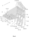
- Each contact element of the first to eighth contact elements 1 to 8 has a first contact section X-1, where X stands for the number of the contact element.
- the reference number 1-1 thus refers to the first contact section of the first contact element 1 and the reference number 8-1 refers to the first contact section of the eighth contact element 8.
- the first contact section X-1 runs at least partially through the plug receiving area 14 and is designed to contact corresponding plug-side contact elements (not shown) when the communication plug is connected to the communication socket 10.
- the first contact section X-1 is preferably resilient and resilient, so that its position can be changed when the communication plug is plugged in and returns to its starting position after the communication plug is removed.
- each contact element of the first to eighth contact elements 1 to 8 has a second contact section X-2, where X stands for the number of the corresponding contact element.
- the reference number 1-2 thus relates to the second contact section of the first contact element 1
- the reference number 8-2 thus relates to the second contact section of the eighth contact element 8.
- the second contact section X-2 is connected to an electrical line.
- a corresponding electrical line can be provided, for example, on a circuit board to which the communication socket 10 is attached.
- the second contact section X-2 can be led out of the housing 12 on a second side (bottom side) of the housing 12, which is preferably opposite the first inner side (see Figure 2 ) to connect the contact element belonging to the contact section X-2 to an electrical line.
- each contact element of the first to eighth contact elements 1 to 8 has an intermediate section X-3 which connects the first contact section X-1 to the second contact section X-2.
- X here again stands for the number of the contact element, so that the reference number 1-3 refers to the intermediate section of the first contact element 1 and the reference number 8-3 refers to the intermediate section of the eighth contact element 8.
- Each first contact section X1 lies in its own imaginary plane, which runs essentially parallel to the insertion direction E. Furthermore, each second contact section X-2 lies in its own imaginary plane, which runs essentially parallel to the insertion direction E. Likewise, each intermediate section X-3 lies in its own imaginary plane, which runs essentially parallel to the insertion direction E.
- the second contact element 2, the fourth contact element 4, the fifth contact element 5 and the seventh contact element 7 extend against the insertion direction E to a first imaginary plane, which runs at an angle of 90° transversely to the insertion direction E
- the first contact element 1, the third contact element 3, the sixth contact element 6 and the eighth contact element 8 extend against the insertion direction E to a second imaginary plane, which runs at an angle of 90° transversely to the insertion direction E, wherein the first imaginary plane of the second imaginary plane, and the first imaginary plane lies relative to the second imaginary plane in the insertion direction E.
- the first and second contact elements 1/2 cross in their course, so that the first contact section 2-1 of the second contact element 2 runs at least partially adjacent to the first contact section 3-1 of the third contact element 3 and the intermediate section 1-3 of the first contact element 1 runs at least partially adjacent to the intermediate section 3-3 of the third contact element 3.
- either the first contact element 1 or the second contact element 2 is guided along one side of the third contact element 3 in sections.
- the first contact section 2-1 of the second contact element is thus arranged between the first contact section 1-1 of the first contact element 1 and the first contact section 3-1 of the third contact element 3.
- the seventh contact element 7 intersects with the eighth contact element 8. Furthermore, the fourth contact element 4 also intersects with the fifth contact element 5.
- the fourth contact element 4 and the fifth contact element 5 intersect in such a way that the first contact section 4-1 of the fourth contact element 4 runs adjacent to the first contact section 3-1 of the third contact element 3 and the intermediate section 5-3 of the fifth contact element 5 runs adjacent to the intermediate section 3-3 of the third contact element 3. Accordingly, the first contact section 5-1 of the fifth contact element runs adjacent to the first contact section 6-1 of the sixth contact element 6 and the intermediate section 4-3 of the fourth contact element runs adjacent to the intermediate section 6-3 of the sixth contact element 6. Accordingly, the intermediate section 4-3 of the fourth contact element runs adjacent to the intermediate section 5-3 of the fifth contact element 5 and between the intermediate section 5-3 of the fifth contact element 5 and the intermediate section 6-3 of the sixth contact element 6.
- the seventh contact element 7 and the eighth contact element 8 are crossed such that the first contact section 7-1 of the seventh contact element 7 runs adjacent to the first contact section 6-1 of the sixth contact element and the intermediate section 8-3 of the eighth contact element 8 runs adjacent to the intermediate section 6-3 of the sixth contact element 6. That is, the intermediate section 8-3 of the eighth contact element 8 runs between the intermediate section 6-3 of the sixth contact element 6 and the intermediate section 7-3 of the seventh contact element 7.
- the first to eighth contact elements 1 to 8 extend in such a way that, viewed opposite to the insertion direction E, the second contact section 2-2 of the second contact element 2 lies between the second contact section 3-2 of the third contact element 3 and the second contact section 1-2 of the first contact element 1. Furthermore, viewed against the insertion direction E, the second contact section 7-2 of the seventh contact element lies between the second contact section 8-2 of the eighth contact element 8 and the second contact section 6-2 of the sixth contact element 6. Furthermore, viewed against the insertion direction E, the second contact section 5-2 of the fifth contact element 5 lies between the second contact section 6-2 of the sixth contact element 6 and the second contact section 4-2 of the fourth contact element 4.
- the second contact section 4-2 of the fourth contact element 4 lies between the second contact section 5-2 of the fifth contact element 5 and the second contact section 3-2 of the third contact element 3. Furthermore, the second contact sections X-2 of the first contact element 1, the third contact element 3, the fifth contact element 5, and the seventh contact element 7 are opposite the second contact sections X-2 of the second contact element 2, the fourth contact element 4, the sixth contact element 6 and the eighth contact element 8 are offset against the insertion direction (see Figure 4 ).
- the contact elements of the crossed contact element pairs each cross at a first Crossing point S1 and a second crossing point S2.
- the first crossing point S1 is located between the first contact section X-1 and the intermediate section X-3 and the second crossing point S2 is located between the intermediate section X-3 and the second contact section X-2.
- a crossing point S1/S2 is formed in that one contact element of the crossing contact elements has an arcuate section S1-22/S2-22 and that the other contact element of the crossing contact elements is guided through the arc formed, preferably in a straight line, in that the two contact elements have a crossing course transverse to the insertion direction E.
- the second contact element 2, the fourth contact element 4 and the eighth contact element 8 can each have an arcuate section S1-22 at the first crossing point S1 and a second arcuate section S2-22 at the second crossing point S2.
- the first arcuate section S1-22 and the second arcuate section S2-22 can be designed to run in the direction of the plug receiving area 14.
- the contact elements 1 to 8 have substantially the same length.
- the length refers to the distance that must be covered when passing through the contact element from end to end of the contact element.
- the length with which the first contact element 1 runs adjacent to the third contact element 3 is between 80% and 120%, particularly preferably between 90% and 110%, of the length with which the second contact element 2 runs adjacent to the third contact element 3.
- the length with which the first contact element 1 runs adjacent to the third contact element 3 is substantially equal to the length with which the second contact element 2 runs adjacent to the third contact element 3.
- the length with which the fourth contact element 4 runs adjacent to the third contact element 3 is between 80% and 120%, particularly preferably between 90% and 110%, of the length with which the fifth Contact element 5 runs adjacent to the third contact element 3.
- the length with which the fourth contact element 4 runs adjacent to the third contact element 3 is substantially equal to the length with which the fifth contact element 5 runs adjacent to the third contact element 3.
- the length with which the seventh contact element 7 runs adjacent to the sixth contact element 6 is between 80% and 120%, particularly preferably between 90% and 110%, of the length with which the eighth contact element 8 runs adjacent to the sixth contact element 6.
- the length with which the seventh contact element 7 runs adjacent to the sixth contact element 6 is substantially equal to the length with which the eighth contact element 8 runs adjacent to the sixth contact element 6.
- each contact element 1 to 8 of the plurality of socket-side contact elements preferably extends from a first end E1 to a second end E2.
- the first contact section X-1 extends, preferably in a straight line, against the insertion direction E and offset from the insertion direction E in the direction of the first inner side of the plug receiving area 14 or the housing 12.
- the first contact section X-1 then changes into a curved section, after which the first contact section X-1 of the contact element extends in the insertion direction E.
- this takes place up to the first crossing point S1.
- the intermediate section X-3 of the contact element follows.
- the intermediate section X-3 follows the bent section approximately at the height of the first crossing point S1.
- the intermediate section X-3 runs essentially parallel to the insertion direction on the top of the housing.
- the intermediate section X-3 is then bent by approximately 90°, with the intermediate section X-3 being guided along the rear side of the housing 12 in the insertion direction E.
- the intermediate section X-3 thus consists of two straight Subsections that are angled at approximately 90° to one another.
- the second crossing point S2 follows for intersecting contact elements, whereby after passing through the second crossing point S2, the second contact section X-2 follows, which is preferably led out of the housing 12.
- the second contact section X-2 follows after the intermediate section X-3 at the level of the second crossing point S2, which is preferably led out of the housing 12.
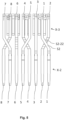
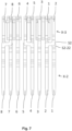
- FIGS. 6 and 7 show a second embodiment of the contact elements 1 to 8 of the communication socket 10, which essentially corresponds to the first embodiment. The differences from the first embodiment are therefore discussed below, with the remaining statements on the first embodiment also applying to the second embodiment.
- the difference between the first embodiment and the second embodiment relates in particular to the design of the arcuate sections S1-22 and S2-22 at the intersection points S1 and S2.
- the intersection points S1 and S2 are formed in that the first contact element 1, the fifth contact element 5 and the seventh contact element 7 each have an arcuate section S1-22 at the first intersection point S1 and a second arcuate section S2-22 at the second intersection point S2.
- the first arcuate section S1-22 and the second arcuate section S2-22 can be designed to run in the direction of the plug receiving area 14 or form an arc pointing in the direction of the plug receiving area 14.
- the second contact element 2 is guided in the area of the first intersection point S1 by means of two bends of approximately 90° each through the first arcuate section S1-22 of the first contact element 1 (see Fig.6 ). As in Fig.7 As can be seen, the second contact element 2 is guided in the region of the second crossing point S2 by means of two bends of approximately 90° each through the second arcuate section S2-22 of the first contact element 1.
- the fourth contact element 4 is connected in the region of the first crossing point S1 by means of two bends of approximately 90° each through the first arc-shaped Section S1-22 of the fifth contact element 5 (see Fig.6 ). As in Fig.7 As can be seen, the fourth contact element 4 is guided in the region of the second crossing point S2 by means of two bends of approximately 90° each through the second arcuate section S2-22 of the fifth contact element 5.
- the eighth contact element 8 is guided in the region of the first crossing point S1 by means of an S-shaped bend through the first curved section S1-22 of the seventh contact element 7 (see Fig.6 ). As in Fig.7 As can be seen, the eighth contact element 8 is guided in the region of the second crossing point S2 by means of two bends of approximately 90° each through the second arcuate section S2-22 of the seventh contact element 7.
Landscapes
- Details Of Connecting Devices For Male And Female Coupling (AREA)
Applications Claiming Priority (1)
| Application Number | Priority Date | Filing Date | Title |
|---|---|---|---|
| DE102023202309.1A DE102023202309A1 (de) | 2023-03-15 | 2023-03-15 | Kommunikationsbuchse, insbesondere eine RJ45-Buchse, Verwendung einer Kommunikationsbuchse und Verfahren zur Herstellung einer Kommunikationsbuchse |
Publications (1)
| Publication Number | Publication Date |
|---|---|
| EP4432484A1 true EP4432484A1 (fr) | 2024-09-18 |
Family
ID=90354496
Family Applications (1)
| Application Number | Title | Priority Date | Filing Date |
|---|---|---|---|
| EP24163403.9A Pending EP4432484A1 (fr) | 2023-03-15 | 2024-03-14 | Prise de communication, en particulier prise rj45, utilisation d'une prise de communication et procédé de fabrication d'une prise de communication |
Country Status (2)
| Country | Link |
|---|---|
| EP (1) | EP4432484A1 (fr) |
| DE (1) | DE102023202309A1 (fr) |
Citations (3)
| Publication number | Priority date | Publication date | Assignee | Title |
|---|---|---|---|---|
| CN103872524A (zh) * | 2014-03-05 | 2014-06-18 | 无锡国丰电子科技有限公司 | 网络连接器插座 |
| US9634433B1 (en) * | 2016-04-13 | 2017-04-25 | Panduit Corp. | Communication jack having a dielectric film between plug interface contacts |
| US9966690B1 (en) * | 2017-01-06 | 2018-05-08 | Kinsun Industries Inc. | Modular electrical connector |
Family Cites Families (1)
| Publication number | Priority date | Publication date | Assignee | Title |
|---|---|---|---|---|
| US5178563A (en) * | 1992-05-12 | 1993-01-12 | Amp Incorporated | Contact assembly and method for making same |
-
2023
- 2023-03-15 DE DE102023202309.1A patent/DE102023202309A1/de active Pending
-
2024
- 2024-03-14 EP EP24163403.9A patent/EP4432484A1/fr active Pending
Patent Citations (3)
| Publication number | Priority date | Publication date | Assignee | Title |
|---|---|---|---|---|
| CN103872524A (zh) * | 2014-03-05 | 2014-06-18 | 无锡国丰电子科技有限公司 | 网络连接器插座 |
| US9634433B1 (en) * | 2016-04-13 | 2017-04-25 | Panduit Corp. | Communication jack having a dielectric film between plug interface contacts |
| US9966690B1 (en) * | 2017-01-06 | 2018-05-08 | Kinsun Industries Inc. | Modular electrical connector |
Also Published As
| Publication number | Publication date |
|---|---|
| DE102023202309A1 (de) | 2024-09-19 |
Similar Documents
| Publication | Publication Date | Title |
|---|---|---|
| DE69417780T2 (de) | Zweiteiliges Abschirmgehäuse für einen Verbinder | |
| EP2476165B1 (fr) | Connecteur pourvu d'un blindage | |
| EP2695249B1 (fr) | Système de mise à la masse à action avancée au moyen d'un élément ressort | |
| EP2783433B1 (fr) | Connecteur avec blindage | |
| DE60002281T2 (de) | Flexibler Verbinder mit integrierter Übertragungsleitung | |
| EP3396793A1 (fr) | Corps de contact pour connecteur à fiche | |
| DE2832243B2 (de) | Mehrreihiger Steckverbinder mit eingepaßtem Schirmblech | |
| DE102007026096A1 (de) | Aderanschlussmodul | |
| EP3323176B1 (fr) | Système de connexion avec codage | |
| EP2510586B1 (fr) | Connecteur en relief et carte de circuits imprimés multicouche | |
| DE102014011903A1 (de) | Verbinder und Verbindervorrichtung | |
| DE602004009268T2 (de) | Verbinder | |
| DE112019006501B4 (de) | Anschlussmodul und Verbinder | |
| CH695034A5 (de) | Steckverbindungsteil einer Steckverbindung fuer hochfrequente Datenuebertragung ueber elektrische Leiter. | |
| DE60307574T2 (de) | Elektrischer Steckverbinder mit kurzer Abstandsanordnung der Kontakte | |
| WO2013029752A1 (fr) | Partie de connecteur enfichable | |
| DE69828552T2 (de) | Modularer Jack-Verbinder | |
| EP4432484A1 (fr) | Prise de communication, en particulier prise rj45, utilisation d'une prise de communication et procédé de fabrication d'une prise de communication | |
| DE2714158C3 (de) | Anschlußvorrichtung für ein vieladriges Rundkabel | |
| DE102014225823A1 (de) | Verfahren zur Herstellung von Verbinderanschlüssen | |
| DE8814033U1 (de) | Elektrische Anschlußgruppe | |
| DE60112139T2 (de) | Aufbau eines abgeschirmten Hochfrequenzkabels | |
| EP3223376B1 (fr) | Prise réseau et procédé de réception et de mise en contact électrique d'un connecteur réseau | |
| DE102024107383B4 (de) | Kombination eines elektrischen verbindungselements mit mindestens zwei kontaktelement-ausrichtungselementen und verfahren zur befestigung eines elektrischen verbindungselements mit einer leiterplatte mittels einer derartigen kombination | |
| LU503495B1 (de) | Steckverbinderteil und Steckverbindersystem |
Legal Events
| Date | Code | Title | Description |
|---|---|---|---|
| PUAI | Public reference made under article 153(3) epc to a published international application that has entered the european phase |
Free format text: ORIGINAL CODE: 0009012 |
|
| STAA | Information on the status of an ep patent application or granted ep patent |
Free format text: STATUS: THE APPLICATION HAS BEEN PUBLISHED |
|
| AK | Designated contracting states |
Kind code of ref document: A1 Designated state(s): AL AT BE BG CH CY CZ DE DK EE ES FI FR GB GR HR HU IE IS IT LI LT LU LV MC ME MK MT NL NO PL PT RO RS SE SI SK SM TR |
|
| STAA | Information on the status of an ep patent application or granted ep patent |
Free format text: STATUS: REQUEST FOR EXAMINATION WAS MADE |
|
| 17P | Request for examination filed |
Effective date: 20250313 |