EP4432503A1 - Commande de l'utilisation de l'énergie d'un panneau solaire - Google Patents
Commande de l'utilisation de l'énergie d'un panneau solaire Download PDFInfo
- Publication number
- EP4432503A1 EP4432503A1 EP23162360.4A EP23162360A EP4432503A1 EP 4432503 A1 EP4432503 A1 EP 4432503A1 EP 23162360 A EP23162360 A EP 23162360A EP 4432503 A1 EP4432503 A1 EP 4432503A1
- Authority
- EP
- European Patent Office
- Prior art keywords
- solar panel
- panel arrangement
- load
- processing unit
- energy
- Prior art date
- Legal status (The legal status is an assumption and is not a legal conclusion. Google has not performed a legal analysis and makes no representation as to the accuracy of the status listed.)
- Pending
Links
Images

Classifications
-
- H—ELECTRICITY
- H02—GENERATION; CONVERSION OR DISTRIBUTION OF ELECTRIC POWER
- H02J—ELECTRIC POWER NETWORKS; CIRCUIT ARRANGEMENTS OR SYSTEMS FOR SUPPLYING OR DISTRIBUTING ELECTRIC POWER; SYSTEMS FOR STORING ELECTRIC ENERGY
- H02J1/00—Circuit arrangements for DC mains or DC distribution networks
- H02J1/14—Balancing load and power generation in DC networks
-
- H—ELECTRICITY
- H02—GENERATION; CONVERSION OR DISTRIBUTION OF ELECTRIC POWER
- H02S—GENERATION OF ELECTRIC POWER BY CONVERSION OF INFRARED RADIATION, VISIBLE LIGHT OR ULTRAVIOLET LIGHT, e.g. USING PHOTOVOLTAIC [PV] MODULES
- H02S50/00—Monitoring or testing of PV systems, e.g. load balancing or fault identification
-
- H—ELECTRICITY
- H02—GENERATION; CONVERSION OR DISTRIBUTION OF ELECTRIC POWER
- H02J—ELECTRIC POWER NETWORKS; CIRCUIT ARRANGEMENTS OR SYSTEMS FOR SUPPLYING OR DISTRIBUTING ELECTRIC POWER; SYSTEMS FOR STORING ELECTRIC ENERGY
- H02J4/00—Circuit arrangements for mains or distribution networks not specified as AC or DC; Circuit arrangements for mains or distribution networks combining AC and DC sections or sub-networks
-
- H—ELECTRICITY
- H02—GENERATION; CONVERSION OR DISTRIBUTION OF ELECTRIC POWER
- H02S—GENERATION OF ELECTRIC POWER BY CONVERSION OF INFRARED RADIATION, VISIBLE LIGHT OR ULTRAVIOLET LIGHT, e.g. USING PHOTOVOLTAIC [PV] MODULES
- H02S40/00—Components or accessories in combination with PV modules, not provided for in groups H02S10/00 - H02S30/00
- H02S40/30—Electrical components
- H02S40/34—Electrical components comprising specially adapted electrical connection means to be structurally associated with the PV module, e.g. junction boxes
-
- H—ELECTRICITY
- H02—GENERATION; CONVERSION OR DISTRIBUTION OF ELECTRIC POWER
- H02S—GENERATION OF ELECTRIC POWER BY CONVERSION OF INFRARED RADIATION, VISIBLE LIGHT OR ULTRAVIOLET LIGHT, e.g. USING PHOTOVOLTAIC [PV] MODULES
- H02S40/00—Components or accessories in combination with PV modules, not provided for in groups H02S10/00 - H02S30/00
- H02S40/30—Electrical components
- H02S40/38—Energy storage means, e.g. batteries, structurally associated with PV modules
-
- H—ELECTRICITY
- H02—GENERATION; CONVERSION OR DISTRIBUTION OF ELECTRIC POWER
- H02J—ELECTRIC POWER NETWORKS; CIRCUIT ARRANGEMENTS OR SYSTEMS FOR SUPPLYING OR DISTRIBUTING ELECTRIC POWER; SYSTEMS FOR STORING ELECTRIC ENERGY
- H02J2101/00—Supply or distribution of decentralised, dispersed or local electric power generation
- H02J2101/20—Dispersed power generation using renewable energy sources
- H02J2101/22—Solar energy
- H02J2101/24—Photovoltaics
-
- H—ELECTRICITY
- H02—GENERATION; CONVERSION OR DISTRIBUTION OF ELECTRIC POWER
- H02J—ELECTRIC POWER NETWORKS; CIRCUIT ARRANGEMENTS OR SYSTEMS FOR SUPPLYING OR DISTRIBUTING ELECTRIC POWER; SYSTEMS FOR STORING ELECTRIC ENERGY
- H02J2101/00—Supply or distribution of decentralised, dispersed or local electric power generation
- H02J2101/20—Dispersed power generation using renewable energy sources
- H02J2101/22—Solar energy
- H02J2101/24—Photovoltaics
- H02J2101/25—Photovoltaics involving maximum power point tracking control for photovoltaic sources
-
- H—ELECTRICITY
- H02—GENERATION; CONVERSION OR DISTRIBUTION OF ELECTRIC POWER
- H02J—ELECTRIC POWER NETWORKS; CIRCUIT ARRANGEMENTS OR SYSTEMS FOR SUPPLYING OR DISTRIBUTING ELECTRIC POWER; SYSTEMS FOR STORING ELECTRIC ENERGY
- H02J2105/00—Networks for supplying or distributing electric power characterised by their spatial reach or by the load
- H02J2105/50—Networks for supplying or distributing electric power characterised by their spatial reach or by the load for selectively controlling the operation of the loads
-
- H—ELECTRICITY
- H02—GENERATION; CONVERSION OR DISTRIBUTION OF ELECTRIC POWER
- H02J—ELECTRIC POWER NETWORKS; CIRCUIT ARRANGEMENTS OR SYSTEMS FOR SUPPLYING OR DISTRIBUTING ELECTRIC POWER; SYSTEMS FOR STORING ELECTRIC ENERGY
- H02J2105/00—Networks for supplying or distributing electric power characterised by their spatial reach or by the load
- H02J2105/50—Networks for supplying or distributing electric power characterised by their spatial reach or by the load for selectively controlling the operation of the loads
- H02J2105/52—Networks for supplying or distributing electric power characterised by their spatial reach or by the load for selectively controlling the operation of the loads for limitation of the power consumption in the networks or in one section of the networks, e.g. load shedding or peak shaving
- H02J2105/53—Networks for supplying or distributing electric power characterised by their spatial reach or by the load for selectively controlling the operation of the loads for limitation of the power consumption in the networks or in one section of the networks, e.g. load shedding or peak shaving for partial power limitation, e.g. entering degraded or current limitation modes
Definitions
- Various embodiments relate to solar panel energy production and monitoring and controlling the usage of energy produced by solar panels.
- renewable energy sources have been under increased study in recent years. Technology related to the generation of renewable energy, such as wind power, wave power, and solar power has developed rapidly. It has been envisaged that the renewable energy can significantly help in fulfilling the constantly increasing demand of electric power.
- the power output of the panel arrangements may vary considerably mainly due to weather or other reasons.
- the actual maximum power output is not known.
- the output power may be large but, for example due to clouds blocking the sun in outside environment or light switched off in indoor environment, in the next moment the output power may drop.
- This variation may have an effect on the services which utilise the power provided by the solar panel arrangement in their operation.
- Fig. 1 illustrates an embodiment of a system for controlling usage of solar panel energy. It should be understood that the system is depicted herein as an example illustrating some embodiments. It is apparent to a person skilled in the art that the system may also comprise other functions and/or structures and not all described functions and structures are required. Different modules of the system may be implemented in one or more physical or logical entities.
- the system may comprise a maximum power point tracking (MPPT) controller 104 connected between a solar panel arrangement (100) and devices acting as a load 102 of the solar panel arrangement.
- MPPT maximum power point tracking
- there may be a DC/DC converter or the like connected between a solar panel arrangement (100) and the devices acting as a load 102
- the system comprises a processing unit 106 controlling the operation of the system.
- the system further comprises a variable load circuitry 108 connected in parallel with the solar panel arrangement 100.
- the processing unit 106 is operationally connected to variable load circuitry and the devices acting as the load 102 of the solar panel arrangement.
- the MPPT controller may be used to optimize power harvesting from the solar panel arrangement as is known in the art. It is a self-controlled device without need for external adjustments.
- the MPPT controller monitors the power provided by the solar panel arrangement in its operation, but it does not provide any indication of the available power.
- variable load may be realized in many various ways as one skilled in the art is aware.
- the load may be realized with various combinations of resistors and semiconductor technology.
- the variable load circuitry 108 is realised with a set of different loading elements, such as resistors, driven by certain order, and controlled by the processing unit.
- the control of resistors may be performed by relays or semiconductor switches or both, for example.
- the variable load circuitry 108 is realised with a single loading element. For example, a field effect transistor, FET, or a transistor which electrical conductivity is adjusted by the processing unit control.
- the system may also comprise an energy storage 110.
- the energy storage may be configured to store energy provided by the solar panel arrangement.
- the energy storage may be a separate unit or in connection with the processing unit.
- the system may also comprise an external controller 112.
- the controller 112 may be operationally connected to the processing unit and to the devices acting as the load 102 of the solar panel arrangement.
- the controller may be a server, or a computing device connected to the rest of the system via Internet, for example.
- the processing unit may communicate with the external controller via a radio connection. Further, the processing unit may also communicate with the devices acting as the load 102 of the solar panel arrangement via a radio connection.
- Fig. 2 illustrates an example of a processing unit. It should be understood that the processing unit is depicted herein as an example illustrating some embodiments. It is apparent to a person skilled in the art that the processing unit may also comprise other functions and/or structures and not all described functions and structures are required. Although the processing unit has been depicted as one entity, different modules and memory may be implemented in one or more physical or logical entities.
- the processing unit 106 comprises a control circuitry 200 configured to control at least part of the operation of the processing unit.
- the control circuitry may be realised with a processor, for example.
- the processing unit may comprise one or more memories 202 for storing data. Furthermore, the memory may store software 204 executable by the control circuitry 200. The memory may be integrated in the control circuitry.
- the processing unit further comprises one or more interfaces 206 for communicating with the system and the devices acting as the load 102 of the solar panel arrangement and other apparatuses, such as the external controller.
- the interfaces may realise a wired or a wireless communication.
- the interfaces may comprise a user interface.
- the user interface may comprise one or more of the following: a display, a speaker, a set of light emitting diodes, for example.
- control circuitry 200 and the memory 202 includes, but is not limited to: logic components, standard integrated circuits, application-specific integrated circuits (ASIC), system-on-a-chip (SoC), application-specific standard products (ASSP), microprocessors, microcontrollers, digital signal processors, special-purpose computer chips, field-programmable gate arrays (FPGA), and other suitable electronics structures.
- ASIC application-specific integrated circuits
- SoC system-on-a-chip
- ASSP application-specific standard products
- microprocessors microcontrollers
- digital signal processors special-purpose computer chips
- FPGA field-programmable gate arrays
- the working memory and the non-volatile memory may be implemented by a random-access memory (RAM), dynamic RAM (DRAM), static RAM (SRAM), a flash memory, a solid state disk (SSD), PROM (programmable read-only memory), a suitable semiconductor, or any other means of implementing an electrical computer memory.
- the software (or computer program code) 204 may be written by a suitable programming language (such as C, C++, assembler or machine language, for example), and the resulting executable code may be stored in the memory 202 and run by the control circuitry 200.
- the software 204 may be in source code form, object code form, executable form, or in some intermediate form, but for use in the control circuitry 200 it is in the executable form.
- There are many ways to structure the computer program code 204 the operations may be divided into modules, subroutines, methods, classes, objects, applets, macros, etc., depending on the software design methodology and the programming language used.
- software libraries i.e. compilations of ready-made functions, which may be utilized by the software 204 for performing a wide variety of standard operations.
- an operating system (such as a general-purpose operating system or a real-time operating system) may provide the software 204 with system services.
- the interfaces 206 of the processing unit may comprise at least one radio transceiver and an antenna operationally connected to the at least one radio transceiver.
- the radio transceiver may operate according to any of the various standard/proprietary technologies utilizing various frequency bands and communication protocols. Standards include, but are not limited to, 802.11 WLAN and various Bluetooth ® standards including Bluetooth ® low energy, BLE.
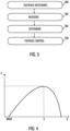
- Fig. 3 is a flowchart illustrating an embodiment for controlling usage of energy provided by a solar panel arrangement.
- step 300 the processing unit is configured to decrease gradually from a given maximum value the resistance of a variable load circuitry connected in parallel with the solar panel arrangement.
- the processing unit is configured to measure the voltage or current output of the solar panel arrangement during the decreasing of the resistance.
- step 304 the processing unit is configured to determine, based on the measurements, the maximum output power provided by the solar panel arrangement.
- the processing unit is configured to provide controlling of the operation of devices acting as the load of the solar panel arrangement based on the determination.
- the processing unit is configured to set the resistance of a variable load circuitry to a given maximum value. Then the processing unit is configured to decrease the resistance of a variable load circuitry gradually from a given maximum value downwards.
- the resistance may be adjusted stepwise.
- the control may be continuous. The control of the resistance may depend on the realisation of the variable load circuitry. For example, if the circuitry is realised with a set of separate resistors, the resistance may be decreased with small steps, while in the case of a semiconductor-based circuitry the control may be continuous.
- the processing unit is configured to measure the voltage or current output of the solar panel arrangement during the decreasing of the resistance.
- the resistance of the variable load As the resistance of the variable load is known and the voltage or current is measured, available power can be calculated. As the resistance is decreased from a given maximum value, the power increases. However, in certain point of the decreasing load, the output power of the solar panel arrangement starts to decrease.
- either voltage or current may be measured to determine the maximum output power provided by the solar panel arrangement.
- Fig. 4 illustrates the variation of the output power.
- resistance R On the x-axis is resistance R and on the y-axis the power P.
- RMAX resistance in decreased starting from the maximum value
- the power increases.
- the resistance reaches the pointy marked as X the power reaches to the maximum power value the solar panel arrangement is able to produce. If the resistance is still decreased beyond the point X, the power starts to decrease.
- the processing unit may stop the measurement process. The processing unit may determine that the maximum output power has been reached.
- the processing unit is configured to perform measurements of the maximum output power provided by the solar panel arrangement at given time intervals.
- the changed maximum available output power can be detected and needed actions taken.
- the processing unit is configured to monitor the voltage output of the solar panel arrangement.
- the processing unit may be configured to initialise measurements of the maximum output power after detecting a predetermined change in the voltage. For example, if the voltage drops a given amount, the measurements may be initialised.
- the processing unit is configured to initiate controlling of the operation of devices acting as the load of the solar panel arrangement based on the determined maximum power value the solar panel arrangement is able to produce.
- the system may comprise the energy storage 110 and the processing unit may determine the amount of energy stored in the energy storage into account when controlling the devices acting as the load of the solar panel arrangement.
- the processing unit may communicate with the external controller 112 which may act as a supervising system.
- the processing unit may transmit information on the maximum output power provided by the solar panel arrangement.
- the external controller may also perform the control of the devices acting as the load instead or in addition to the processing unit.
- the devices acting as the load of the solar panel arrangement may be any kind of devices that operate or utilise electric power.
- the devices may be small wearable devices, indoor or outdoor sensors, location tracking infrastructure devices, such as anchors, routers, and beacons, motors or engines, lights, battery chargers or computing devices, for example.
- the processing unit may act as the load of the solar panel arrangement.
- the devices may also have their own energy harvesting unit. Thus, they may utilise energy they have harvested themselves and energy provided by the solar panel arrangement
- the solar panel arrangement may be of any size, from a small size of smartwatch display to bigger outdoor systems. It may be also bendable for example in wearable band.
- the processing unit can control the devices acting as the load of the solar panel arrangement in various ways.
- the processing unit may, based on the determination of the maximum available output power the solar panel arrangement is able to provide, control operation mode of the devices. Further, the processing unit may control the energy usage of devices.
- the devices may have different operation modes in which the energy consumption of the device is different.
- the devices may have a full operating mode where the energy consumption is largest and reduced functionality modes with reduced energy consumption and a sleep mode with the smallest energy consumption.
- the processing unit may store information of the different modes of the devices and select the suitable mode based on the available output power. As mentioned, the amount of energy stored in an energy storage may be taken into account.
- the devices may be equipped with a radio transceiver.
- the processing unit may change the radio communication mode of the devices from low latency, high data rate communication to simple low power beaconing mode to save power, for example.
- the processing unit may be configured to store information on the maximum output power provided by the solar panel arrangement at given time intervals and control the operation of the devices acting as the load based on the stored information. For example, the processing unit may, after being installed and used for a length of time, determine that at given times of day the available energy is always reduced. This information may be taken into account in the control of the devices. In addition, the information may be utilised in planning maintenance operations of the solar panel arrangement. For example, if it is noticed that the maximum power provided by the solar panel arrangement has been constantly decreasing, cleaning of the panels may be required.
- the processing unit may store operating mode rules which prefer certain modes. Based on the maximum output power the solar panel arrangement is capable of providing and energy stored in the energy storage the processing unit may indicate that the devices acting as the load can perform tasks required from them. A task in practice my mean a certain operating mode can be utilised for a required time, for example.
- the processing unit may communicate with the external controller 112 which may act as a supervising system.
- the processing unit can also indicate that to the supervising system that tasks can or cannot be done.
- the external controller 112 or supervising system may know each device status, and it can control both the processing unit and the devices acting as the load.
- the external controller 112 or supervising system may control more than one system each equipped with a separate processing unit.
- the external controller 112 or supervising system may transmit a command to use a given power mode to execute tasks.
- Supervising system can also generate tasks to devices that some of them are more active and rest of them are sleeping, harvesting mainly energy to storage. After harvesting the supervising can swap tasks to these devices.
- the supervising system or the processing unit stores data about what the devices acting as the load can perform with given available energy levels. If the available energy is reduced, then devices may be controlled to maintain minimum required performance level. In case of the available energy level is high, then the device may be controlled to operate in maximum performance level.
- the supervising system or the processing unit stores data about time instants when high and low performance level is required and can perform system optimization so that requirements are met.
- energy may be stored to the energy storage 110 to be used when high performance level is required.
- measured power level can be also used to optimize device positioning during deployment. For example, if a system with a solar panel arrangement, processing unit and a device acting as a load is attached to lamp or to the wall, the system can inform real time to installing personnel what is harvested power level in numbers or simply if is it above required level which is needed for operation. Indication can be shown visually or audible by system itself, direct radio message like beaconing or by the supervising system.
- the supervising system or the processing unit may provide an indication of situations where the maximum energy the solar panel arrangement can provide is less than normal.
- the supervising system or the processing unit may store normal allowed values for the maximum energy, and if it is determined that the measured values are below normal or stay very low for a given length of time, an alarm may be indicated. It may be that the solar panels need cleaning, for example.
- the operation of the devices acting as the load may be adjusted in a controlled manner.
- the operation of the devices can be maintained, for example in a reduced energy consumption mode of, if need be, in a sleep mode. No abrupt shutting down of devices is required. Further, the operation of the solar panels may be monitored.
Landscapes
- Engineering & Computer Science (AREA)
- Power Engineering (AREA)
- Charge And Discharge Circuits For Batteries Or The Like (AREA)
Priority Applications (2)
| Application Number | Priority Date | Filing Date | Title |
|---|---|---|---|
| EP23162360.4A EP4432503A1 (fr) | 2023-03-16 | 2023-03-16 | Commande de l'utilisation de l'énergie d'un panneau solaire |
| US18/605,467 US20240313703A1 (en) | 2023-03-16 | 2024-03-14 | Controlling usage of solar panel energy |
Applications Claiming Priority (1)
| Application Number | Priority Date | Filing Date | Title |
|---|---|---|---|
| EP23162360.4A EP4432503A1 (fr) | 2023-03-16 | 2023-03-16 | Commande de l'utilisation de l'énergie d'un panneau solaire |
Publications (1)
| Publication Number | Publication Date |
|---|---|
| EP4432503A1 true EP4432503A1 (fr) | 2024-09-18 |
Family
ID=85703929
Family Applications (1)
| Application Number | Title | Priority Date | Filing Date |
|---|---|---|---|
| EP23162360.4A Pending EP4432503A1 (fr) | 2023-03-16 | 2023-03-16 | Commande de l'utilisation de l'énergie d'un panneau solaire |
Country Status (2)
| Country | Link |
|---|---|
| US (1) | US20240313703A1 (fr) |
| EP (1) | EP4432503A1 (fr) |
Citations (3)
| Publication number | Priority date | Publication date | Assignee | Title |
|---|---|---|---|---|
| US20180090939A1 (en) * | 2016-09-29 | 2018-03-29 | Tokitae Llc | Devices and methods for use 5 with refrigeration devices including temperature-controlled container systems |
| US20210057918A1 (en) * | 2016-09-07 | 2021-02-25 | Commissariatá I'Éngergie Atomique et aux Énergies Alternatives | Electric energy transmission circuit |
| US20220190598A1 (en) * | 2020-12-16 | 2022-06-16 | Joseph Azzolini | Maximum power point tracking through load management |
-
2023
- 2023-03-16 EP EP23162360.4A patent/EP4432503A1/fr active Pending
-
2024
- 2024-03-14 US US18/605,467 patent/US20240313703A1/en not_active Abandoned
Patent Citations (3)
| Publication number | Priority date | Publication date | Assignee | Title |
|---|---|---|---|---|
| US20210057918A1 (en) * | 2016-09-07 | 2021-02-25 | Commissariatá I'Éngergie Atomique et aux Énergies Alternatives | Electric energy transmission circuit |
| US20180090939A1 (en) * | 2016-09-29 | 2018-03-29 | Tokitae Llc | Devices and methods for use 5 with refrigeration devices including temperature-controlled container systems |
| US20220190598A1 (en) * | 2020-12-16 | 2022-06-16 | Joseph Azzolini | Maximum power point tracking through load management |
Non-Patent Citations (1)
| Title |
|---|
| SANGSOO PARK ET AL: "Intelligent control for a distributed flexible network photovoltaic system using autonomous control and agent", ELECTRONICS AND COMMUNICATIONS IN JAPAN, WILEY-BLACKWELL PUBLISHING, INC, US, vol. 96, no. 1, 18 December 2012 (2012-12-18), pages 14 - 24, XP072450252, ISSN: 1942-9533, DOI: 10.1002/ECJ.11432 * |
Also Published As
| Publication number | Publication date |
|---|---|
| US20240313703A1 (en) | 2024-09-19 |
Similar Documents
| Publication | Publication Date | Title |
|---|---|---|
| CA2597145C (fr) | Systeme de charge pour dispositif de terrain | |
| JP6122974B2 (ja) | センサノード、及びセンサノードの制御方法 | |
| US8892411B2 (en) | Information processor, power generation determining method, and program | |
| US9651971B2 (en) | Control device, power control system, and power control method | |
| US11199335B2 (en) | Variable air volume diffuser and method of operation | |
| JP5681594B2 (ja) | 無線電力動作型機器 | |
| US20150153714A1 (en) | Renewable energy power generation prediction system and method and power allocation system | |
| US10978876B2 (en) | Maximum power point tracking hybrid control of an energy storage system | |
| JP6115262B2 (ja) | センサ装置およびモニタリングシステム | |
| JP6227189B2 (ja) | 電源システム | |
| JP2010231456A (ja) | 電源システム | |
| JP2009517829A (ja) | 照明システム制御デバイスを充電するシステムおよび方法 | |
| JP2017009305A (ja) | センシング装置及びセンシングシステム | |
| EP4432503A1 (fr) | Commande de l'utilisation de l'énergie d'un panneau solaire | |
| JP6056976B2 (ja) | 電子装置 | |
| KR102358869B1 (ko) | 멀티 인터페이스 통신 기반의 원격제어장치를 활용한 태양광 발전 관리 시스템 | |
| US10326281B2 (en) | Power conditioner, photovoltaic power generation device, and control method | |
| JP2018207551A (ja) | 環境発電型無線装置及びシステム | |
| Kašper et al. | Conceptual design of the power supply for the mobile monitoring unit | |
| JP2022050874A (ja) | 環境情報提供システム、センサ装置、ゲートウェイ装置、センサ装置の制御方法、及びセンサ装置のプログラム | |
| CN120848707B (zh) | 散热控制方法、电子设备 | |
| CN118944291A (zh) | 光伏电站功率控制方法、装置及系统 | |
| WO2016033597A1 (fr) | Commutateur de charge intelligent pour système électrique solaire, et procédé d'utilisation de ce commutateur | |
| CN120159803A (zh) | 风扇控制方法和储能系统 |
Legal Events
| Date | Code | Title | Description |
|---|---|---|---|
| PUAI | Public reference made under article 153(3) epc to a published international application that has entered the european phase |
Free format text: ORIGINAL CODE: 0009012 |
|
| STAA | Information on the status of an ep patent application or granted ep patent |
Free format text: STATUS: THE APPLICATION HAS BEEN PUBLISHED |
|
| AK | Designated contracting states |
Kind code of ref document: A1 Designated state(s): AL AT BE BG CH CY CZ DE DK EE ES FI FR GB GR HR HU IE IS IT LI LT LU LV MC ME MK MT NL NO PL PT RO RS SE SI SK SM TR |
|
| STAA | Information on the status of an ep patent application or granted ep patent |
Free format text: STATUS: REQUEST FOR EXAMINATION WAS MADE |
|
| 17P | Request for examination filed |
Effective date: 20250228 |