EP4434443A1 - Étalonnage de mesures de paramètres de conduit - Google Patents
Étalonnage de mesures de paramètres de conduit Download PDFInfo
- Publication number
- EP4434443A1 EP4434443A1 EP23163671.3A EP23163671A EP4434443A1 EP 4434443 A1 EP4434443 A1 EP 4434443A1 EP 23163671 A EP23163671 A EP 23163671A EP 4434443 A1 EP4434443 A1 EP 4434443A1
- Authority
- EP
- European Patent Office
- Prior art keywords
- duct
- mer
- milk
- cycle
- parameter value
- Prior art date
- Legal status (The legal status is an assumption and is not a legal conclusion. Google has not performed a legal analysis and makes no representation as to the accuracy of the status listed.)
- Withdrawn
Links
Images




Classifications
-
- A—HUMAN NECESSITIES
- A61—MEDICAL OR VETERINARY SCIENCE; HYGIENE
- A61B—DIAGNOSIS; SURGERY; IDENTIFICATION
- A61B5/00—Measuring for diagnostic purposes; Identification of persons
- A61B5/42—Detecting, measuring or recording for evaluating the gastrointestinal, the endocrine or the exocrine systems
- A61B5/4261—Evaluating exocrine secretion production
- A61B5/4288—Evaluating exocrine secretion production mammary secretions
-
- A—HUMAN NECESSITIES
- A61—MEDICAL OR VETERINARY SCIENCE; HYGIENE
- A61B—DIAGNOSIS; SURGERY; IDENTIFICATION
- A61B5/00—Measuring for diagnostic purposes; Identification of persons
- A61B5/43—Detecting, measuring or recording for evaluating the reproductive systems
- A61B5/4306—Detecting, measuring or recording for evaluating the reproductive systems for evaluating the female reproductive systems, e.g. gynaecological evaluations
- A61B5/4312—Breast evaluation or disorder diagnosis
-
- A—HUMAN NECESSITIES
- A61—MEDICAL OR VETERINARY SCIENCE; HYGIENE
- A61B—DIAGNOSIS; SURGERY; IDENTIFICATION
- A61B5/00—Measuring for diagnostic purposes; Identification of persons
- A61B5/0059—Measuring for diagnostic purposes; Identification of persons using light, e.g. diagnosis by transillumination, diascopy, fluorescence
-
- A—HUMAN NECESSITIES
- A61—MEDICAL OR VETERINARY SCIENCE; HYGIENE
- A61M—DEVICES FOR INTRODUCING MEDIA INTO, OR ONTO, THE BODY; DEVICES FOR TRANSDUCING BODY MEDIA OR FOR TAKING MEDIA FROM THE BODY; DEVICES FOR PRODUCING OR ENDING SLEEP OR STUPOR
- A61M1/00—Suction or pumping devices for medical purposes; Devices for carrying-off, for treatment of, or for carrying-over, body-liquids; Drainage systems
- A61M1/06—Milking pumps
-
- A—HUMAN NECESSITIES
- A61—MEDICAL OR VETERINARY SCIENCE; HYGIENE
- A61M—DEVICES FOR INTRODUCING MEDIA INTO, OR ONTO, THE BODY; DEVICES FOR TRANSDUCING BODY MEDIA OR FOR TAKING MEDIA FROM THE BODY; DEVICES FOR PRODUCING OR ENDING SLEEP OR STUPOR
- A61M1/00—Suction or pumping devices for medical purposes; Devices for carrying-off, for treatment of, or for carrying-over, body-liquids; Drainage systems
- A61M1/06—Milking pumps
- A61M1/062—Pump accessories
-
- G—PHYSICS
- G01—MEASURING; TESTING
- G01F—MEASURING VOLUME, VOLUME FLOW, MASS FLOW OR LIQUID LEVEL; METERING BY VOLUME
- G01F1/00—Measuring the volume flow or mass flow of fluid or fluent solid material wherein the fluid passes through a meter in a continuous flow
- G01F1/66—Measuring the volume flow or mass flow of fluid or fluent solid material wherein the fluid passes through a meter in a continuous flow by measuring frequency, phase shift or propagation time of electromagnetic or other waves, e.g. using ultrasonic flowmeters
- G01F1/661—Measuring the volume flow or mass flow of fluid or fluent solid material wherein the fluid passes through a meter in a continuous flow by measuring frequency, phase shift or propagation time of electromagnetic or other waves, e.g. using ultrasonic flowmeters using light
-
- G—PHYSICS
- G01—MEASURING; TESTING
- G01F—MEASURING VOLUME, VOLUME FLOW, MASS FLOW OR LIQUID LEVEL; METERING BY VOLUME
- G01F1/00—Measuring the volume flow or mass flow of fluid or fluent solid material wherein the fluid passes through a meter in a continuous flow
- G01F1/66—Measuring the volume flow or mass flow of fluid or fluent solid material wherein the fluid passes through a meter in a continuous flow by measuring frequency, phase shift or propagation time of electromagnetic or other waves, e.g. using ultrasonic flowmeters
- G01F1/663—Measuring the volume flow or mass flow of fluid or fluent solid material wherein the fluid passes through a meter in a continuous flow by measuring frequency, phase shift or propagation time of electromagnetic or other waves, e.g. using ultrasonic flowmeters by measuring Doppler frequency shift
-
- G—PHYSICS
- G01—MEASURING; TESTING
- G01F—MEASURING VOLUME, VOLUME FLOW, MASS FLOW OR LIQUID LEVEL; METERING BY VOLUME
- G01F25/00—Testing or calibration of apparatus for measuring volume, volume flow or liquid level or for metering by volume
- G01F25/10—Testing or calibration of apparatus for measuring volume, volume flow or liquid level or for metering by volume of flowmeters
-
- A—HUMAN NECESSITIES
- A61—MEDICAL OR VETERINARY SCIENCE; HYGIENE
- A61M—DEVICES FOR INTRODUCING MEDIA INTO, OR ONTO, THE BODY; DEVICES FOR TRANSDUCING BODY MEDIA OR FOR TAKING MEDIA FROM THE BODY; DEVICES FOR PRODUCING OR ENDING SLEEP OR STUPOR
- A61M2205/00—General characteristics of the apparatus
- A61M2205/33—Controlling, regulating or measuring
- A61M2205/3306—Optical measuring means
-
- A—HUMAN NECESSITIES
- A61—MEDICAL OR VETERINARY SCIENCE; HYGIENE
- A61M—DEVICES FOR INTRODUCING MEDIA INTO, OR ONTO, THE BODY; DEVICES FOR TRANSDUCING BODY MEDIA OR FOR TAKING MEDIA FROM THE BODY; DEVICES FOR PRODUCING OR ENDING SLEEP OR STUPOR
- A61M2205/00—General characteristics of the apparatus
- A61M2205/70—General characteristics of the apparatus with testing or calibration facilities
Definitions
- This invention relates to the field of calibrating duct parameter measurements, and in particular to the field of calibrating a duct parameter measurement of a milk duct of a subject.
- Breastfeeding is crucial for healthy development of a newborn baby. Indeed, the best source of nutrition for a baby is human milk given by a breastfeeding mother. The milk contains antibodies which help protect against many common childhood and future illnesses. The World Health Organization recommends to exclusively breastfeed for at least six months, meaning no other foods or liquids are provided.
- the infant interacts with the nipple applying both vacuum cycles and tongue pressures to extract milk. Moreover, the infant stimulates the nipple and areola complex that leads to release of oxytocin and ejection of milk.
- the combination of the applied vacuum, the contracting response of the cells around the ducts (myoepithelial cells) to oxytocin release and the pressure of milk flowing through the ducts leads to opening of the milk ducts and release of milk. In this process, the milk ducts show highly dynamic behavior, going from a collapsed to a swollen milk-filled state.
- mastitis is a common complication occurring during breastfeeding, being a painful inflammation of the breast tissue. It is most often caused by clogged milk ducts that lead to milk stasis (remaining milk in the breast after a feed giving a restricted milk flow), sometimes in combination with infectious bacteria. Clogged milk ducts refer to milk ducts with some obstruction, e.g. caused by milk clutters. This can lead to nipples that are painful, feel warm, cause discomfort and, as stated above, lead to the development of mastitis.
- Some signs can be predictive of clogged ducts, including localized redness of the skin, a hard or semi-hard lump on the breast, and a feeling of pain during milk ejection reflex.
- ultrasound-based imaging technologies are used to image milk ducts. This imaging method is difficult to translate to a home solution. Also, ultrasound imaging requires a coupling between the ultrasound transducer and the tissue, e.g., using an ultrasound gel, which is inconvenient and also not desirable as it may end up in the milk. Furthermore, ultrasound does not have a high enough resolution to see narrower sections of the ducts, duct endings being of the order of 0.07 mm in size.
- Milk ejection reflex is crucial in successful lactation. As the milk flows through the mammary gland in response to MER, the pressure within the milk ducts increases. As the milk pressure increases, there is a corresponding transient increase in duct diameters demonstrated by ultrasound monitoring of milk ducts.
- Ejection of milk after MER takes place 30 seconds to 1 minute after release of oxytocin and typically lasts between 45 seconds and 4 minutes. Milk ejection reflex occurs several times during a feeding or expression session with a few minutes in between. The first MER is usually the strongest and releases significantly more milk than subsequent milk ejections, regardless of vacuum level applied. Successive ejections are less strong and rarely directly perceived.
- MER occurs on average 4 to 5 times, which allows the entire mammary system to be activated more than once to efficiently remove all the milk from the alveoli and empty the breast. Moreover, MER has been shown to present the same characteristics for an individual, for instance, the number of MER cycles in an individual's breastfeeding session.
- a method for calibrating a duct parameter measurement of a milk duct of a breast of a subject is provided.
- the method comprises: detecting at least one milk ejection reflex (MER) parameter value of at least one MER cycle of the subject; determining at least one duct parameter value of a milk duct of the subject; and calibrating the determined at least one duct parameter value based on the detected at least one MER parameter value to generate at least one calibrated duct parameter value.
- MER milk ejection reflex
- Proposed concepts thus aim to provide schemes, solutions, concept, designs, methods and systems pertaining to calibrating a duct parameter measurement of a milk duct of a breast of a subject.
- embodiments aim to provide a method for calibrating a duct parameter measurement of a milk duct of a breast of a subject by using a detected MER parameter value, such as the peak of the MER cycle, to calibrate a duct parameter value of the milk duct of the subject.
- duct parameter values may be accurately compared longitudinally, i.e. over time, or between breasts. This may allow the accurate and reliable monitoring of duct health and the assessment of the risk of milk duct clogging.
- a duct parameter value may be duct diameter or milk flow rate.
- an MER parameter value may be whether the MER cycle is the first in a breastfeeding session or it may be the identification of the peak of the MER cycle. Identification of the peak of the MER cycle may comprise determining its time of occurrence.
- duct parameter values such as duct diameter
- the context of the duct parameter value needs to be taken into account to ensure that when comparing to other values, the comparison is useful and informative.
- a comparison between calibrated values can then be used to monitor duct health and potentially to indicate a risk of the milk duct clogging or being clogged.
- one or more duct parameter values can be calibrated. For instance, the milk flow rate both at the start of the MER cycle and at the peak of the MER cycle can be used to calculate a calibrated milk flow difference. This calibrated milk flow difference value can then be compared across different breastfeeding sessions for the same subject to monitor their ducts. If this value substantially drops, this may then indicate milk duct clogging.
- the duct diameter or milk flow rate can be determined at that same exact point in each breastfeeding session and thus can be fairly compared to one another. This comparison may, for example, be for the same breast over time or between a subject's right and left breasts in the same session. If the values are different from one another by more than a threshold amount, this might then indicate a risk of milk duct clogging.
- a way to reliably calibrate and personalise duct parameter values is provided, and this can be put to use in the detection of milk duct clogging, or a risk of milk duct clogging.
- the inventors have realised that in order to correctly and reliably identify early signs of duct clogging or blockage, it is necessary to take into account the phase of the milk ejection reflex e.g., whether the measurement is taken at the peak of an MER or between MERs, and whether at the first peak or at subsequent peaks.
- This invention may be of particular use implemented into a breast pump or a nipple shield, so that the health of milk ducts of a breast of a subject may be monitored as part of a daily routine in a non-intrusive way.
- an improved method calibrating a duct parameter measurement of a milk duct of a breast of a subject may be supported by the proposed concept(s).
- the at least one MER parameter value may comprise at least one of: the peak of the MER cycle; the duration of the MER cycle; whether the MER cycle is the first in a breastfeeding or milk expression session; the start of the MER cycle; the end of the MER cycle; the duration from the start to the peak of the MER cycle; the duration from the peak to the end of the MER cycle.
- the duct parameter value can be calibrated.
- the peak of an MER cycle can be used, for instance, to calibrate a maximum duct diameter value as it is a very specific and identifiable spot within an MER cycle. It can therefore be used to ensure that comparisons between duct diameter values are reliable and that any variation is not due to fluctuations within the MER cycle itself.
- the duration of an MER cycle can be used to determine, for instance, the total milk volume expressed over a single MER cycle. Whether the MER cycle is the first in a breastfeeding or milk expression session can be used to help calibrate the duct parameter value as the first MER cycle is usually the strongest and releases significantly more milk than subsequent milk ejections.
- the start of an MER cycle can be used to determine, for instance, the time to milk ejection.
- the end of an MER cycle can be used to determine, for instance, a duct parameter value between MER cycles in a single breastfeeding session, e.g. at the end of the first MER cycle in a session, before the second.
- the duration from the start to the peak of an MER cycle can be used to determine, for instance, the leading edge of the duct diameter.
- the duration from the peak to the end of an MER cycle can be used to determine, for instance, the falling edge of the duct diameter.
- detecting at least one MER parameter value of at least one MER cycle of the subject may comprise obtaining measurements of the at least one MER cycle of the subject from an optical imaging system.
- MER parameters can be detected non-invasively and in a way that may seamlessly integrate into an efficient breastfeeding workflow. This is in contrast to intraductal pressure measurements or the use of electrodes or ultrasound gel.
- the optical imaging system may be a stand-alone unit or, for instance, integrated into a system such as a breast pump for carrying out any herein disclosed method.
- determining the at least one duct parameter value may be based on the obtained measurements of the at least one MER cycle of the subject.
- the optical imaging system may simultaneously measure milk flow and duct geometry parameter values. Alternatively, the optical imaging system may only measure one parameter at a time. Milk ducts can be identified in images obtained from the optical imaging system and their geometry can thus be analysed. For example, milk duct diameter can be measured as a simple linear dimension within a captured image. The change in geometry during a breastfeeding or milk expression session, which can be determined from the obtained images, can then be used to help detect milk duct blockages or partial blockages.
- the at least one duct parameter value may comprise at least one of: milk flow rate; maximum milk flow rate; milk flow volume; total milk volume; duct diameter; change of duct diameter; rate of change of duct diameter; rate of change of duct diameter from the start to the peak of the MER cycle; duct volume; change of duct volume; and rate of change of duct volume.
- the at least one calibrated duct parameter value may be indicative of at least a partial clogging of the milk duct of the subject. In this way, partial clogging of the milk duct of the subject may be determined from the calibrated value and the subject may be alerted that their milk duct is partially clogged and at risk of substantial or full clogging.
- the method may further comprise determining a risk value indicating a risk of the milk duct of the subject clogging based on the at least one calibrated duct parameter value.
- a risk of the milk duct clogging may be determined. For instance, whether the milk duct is partially, substantially, or fully clogged may be determined.
- the risk value may indicate a probability or likelihood of the milk duct clogging in the near future.
- the risk value may indicate a probability or likelihood of the milk duct being partially or fully clogged at the time the duct parameter value was determined. The subject may then be informed of this information.
- determining a risk value may comprise comparing the at least one calibrated duct parameter value to a threshold value, and determining the risk value based on the comparison result.
- the use of a threshold may provide an efficient way to determine whether the milk duct is clogged or at risk of clogging, either partially, substantially, or fully.
- the threshold value may be determined based on at least one past calibrated duct parameter value of the subject's milk duct.
- the use of a past calibrated duct parameter value of the subject's milk duct may provide a personalized threshold that takes account of the fact that milk duct parameters, such as milk flow rate or duct diameter, can substantially vary between different subjects.
- the determining of a risk of milk duct clogging can be personalized to individual subjects based off their past calibrated duct parameter values.
- Past calibrated duct parameter values may be associated with individual milk ducts of the subject, and thus thresholds may be personalized to the exact milk duct of the subject.
- the threshold may be based on at least one past calibrated duct parameter value of any of the subject's milk ducts.
- the threshold value may be determined based on at least one calibrated duct parameter value of a different milk duct of the subject.
- the use of a calibrated duct parameter value of a different milk duct of the subject to help inform the threshold value may allow variation between ducts in a single breast or between breasts to be indicative of milk duct clogging.
- the milk duct of the subject may be in a different breast to the different milk duct.
- the use of a calibrated duct parameter value of a different milk duct of the subject to help inform the threshold value may allow variation between breasts to be indicative of milk duct clogging.
- calibrated duct parameter values may be determined for the left and right breasts simultaneously, and this information may be used to help determine whether one breast is more at risk of clogging than the other.
- calibrated duct parameter values may be determined for the left and right breasts at different times.
- the at least one duct parameter value may comprise both change of duct diameter and maximum flow rate.
- the use of these two parameters, and in particular the relationship between them, has been found to be particularly beneficial in assessing the risk of milk duct clogging.
- the method may further comprise generating a display control signal, the display control signal describing the determined risk. This may provide a way of presenting to the subject the risk of one of their milk ducts being clogged.
- the display control signal may comprise feedback that the milk duct most recently measured is clogged or at risk of clogging.
- the display control signal may comprise feedback indicating an area at which a milk-blocked duct has been identified. This may enable the subject to take corrective curative action.
- a computer program comprising code means for implementing the method of any herein disclosed method when said program is run on a processing system.
- a system for calibrating a duct parameter measurement of a milk duct of a subject comprising a processor arrangement configured to: detect at least one milk ejection reflex (MER) parameter value of at least one MER cycle of the subject; determine at least one duct parameter value of a milk duct of the subject; and calibrate the determined at least one duct parameter value based on the detected at least one MER parameter value to generate at least one calibrated duct parameter value.
- MER milk ejection reflex
- the system may further comprise an optical imaging unit, configured to obtain measurements of the at least one MER cycle of the subject, wherein detecting the at least one MER parameter value is based on the obtained measurements.
- the system does not require an optical imaging unit, as the system may receive information about at least one MER cycle of the subject from a stand-alone unit, such as a stand-alone optical imaging unit or from a bottle unit that, for example, monitors the rate of filling. Integrating an optical imaging unit into the system, however, may provide a comprehensive system capable of carrying out any herein disclosed method.
- a breast pump comprising any herein disclosed system.
- Implementations in accordance with the present disclosure relate to various techniques, methods, schemes and/or solutions pertaining to calibrating a duct parameter measurement of a milk duct of a subject.
- a number of possible solutions may be implemented separately or jointly. That is, although these possible solutions may be described below separately, two or more of these possible solutions may be implemented in one combination or another.
- Embodiments of the invention aim to provide a method for calibrating a duct parameter measurement of a milk duct of a subject. This can be achieved by detecting an MER parameter value of an MER cycle of the subject, and then using this MER parameter value to calibrate a determined duct parameter value of the subject's milk duct.
- Proposed concepts thus aim to take into account the context in which a duct parameter value of a milk duct of the subject was determined, and by doing so to calibrate it so that it may be more usefully compared to other calibrated duct parameter values to potentially indicate whether a milk duct is clogged or at risk of clogging.
- phase of the milk ejection reflex e.g., whether a measurement is taken at the peak of an MER cycle or between MER cycles, and whether at the first peak or at subsequent peaks. In such a manner, it becomes possible to calibrate and/or compare longitudinal measurements with higher accuracy.
- FIG. 1 there is depicted a simplified flow diagram of a method 100 for calibrating a duct parameter measurement of a milk duct of a subject according to a proposed embodiment.
- the method 100 begins with the step 110 of detecting at least one milk ejection (MER) parameter value of at least one MER cycle of the subject.
- MER milk ejection
- the at least one MER parameter value comprises at least one of: the peak of the MER cycle; the duration of the MER cycle; whether the MER cycle is the first in a breastfeeding or milk expression session; the start of the MER cycle; the end of the MER cycle; the duration from the start to the peak of the MER cycle; the duration from the peak to the end of the MER cycle.
- the duct parameter value can be calibrated.
- the peak of an MER cycle can be used, for instance, to calibrate a maximum duct diameter value as it is a very specific and identifiable spot within an MER cycle, and so can be used to ensure that comparison between duct diameter values is reliable and that any variation is not due to fluctuations within the MER cycle itself.
- the duration of an MER cycle can be used to determine, for instance, the total milk volume expressed over a single MER cycle as well as other relevant duct parameter values such as milk flow or milk flow rate.
- the start of an MER cycle can be used to determine, for instance, the time to milk ejection.
- the end of an MER cycle can be used to determine, for instance, a duct parameter value between MER cycles in a single breastfeeding session, e.g. at the end of the first MER cycle in a session, before the second.
- the duration from the start to the peak of an MER cycle can be used to determine, for instance, the leading edge of the duct diameter.
- the duration from the peak to the end of an MER cycle can be used to determine, for instance, the falling edge of the duct diameter.
- Any optical or non-image-based means may be utilised to detect an MER cycle of the subject using technologies and solutions such as, for instance, validated detection and measurement techniques. These may be, for example, maternal circulating oxytocin, intraductal pressure, ultrasound imaging, milk flow rates, bioimpedance analysis, and thermal imaging.
- At least one duct parameter of a milk duct of the subject is determined.
- the at least one duct parameter value comprises at least one of: milk flow rate; maximum milk flow rate; milk flow volume; total milk volume; duct diameter; change of duct diameter; rate of change of duct diameter; rate of change of duct diameter from the start to the peak of the MER cycle; duct volume; change of duct volume; and rate of change of duct volume.
- the at least one duct parameter value may comprise both change of duct diameter and maximum flow rate.
- the use of these two parameters, and in particular the relationship between them, has been found to be particularly beneficial in assessing the risk of a milk duct clogging.
- Software and/or algorithms may be used to determine the at least one duct parameter value of a milk duct of the subject.
- a processor may execute an algorithm to extract duct diameter, duct volume and/or milk flow rate/volume from measurements, such as images.
- the milk duct diameter increases as the pressure in the milk duct rises and subsequently decreases as the pressure decreases due to milk outflow during an MER cycle.
- Software and/or algorithms may establish a relationship between the changes in duct diameter and a maximum milk flow rate to be used as a reference calibration or standardized time point.
- a method may be provided that is able to establish and assess the existence of clogged ducts by linking and comparing a reference or threshold duct diameter, peak flow, rate of change of diameter, or rate of change of duct diameter in the leading edge.
- software and/or algorithms may be used to calibrate a duct parameter value to a known point of an MER cycle.
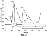
- FIG. 2 there is depicted a diagram showing how the diameter of a milk duct of a subject changes over time during an breastfeeding session.
- the first MER cycle in the breastfeeding session is from point 210 to point 230, with point 220 being the peak of the first MER cycle.
- Point 230 is also the start of the second MER cycle in the session, with point 240 being the peak of the second MER cycle.
- the duration from the start of the session to point 210 is known as time to milk ejection.
- the duration from point 210 to point 220 is known as time to peak.
- the duration from point 210 to point 230 is known as the duration of a MER cycle.
- the duration from the peak to the end of the MER cycle is the duration from point 220 to point 230.
- the graph line from point 210 to point 220 as known as the leading edge.
- the graph line from point 220 to point 230 is known as the falling edge.
- the maximum duct diameter is found at the peak of the first MER cycle, i.e. point 220.
- the change of duct diameter may be the change between the duct diameter at point 220 and point 210 or 230, depending on which is lower.
- a time integration of area under the curve between points 210 and 230 can provide a duct volume (lumen) parameter. If the y-axis were milk flow rate instead, the total milk volume expressed over the first MER cycle could be calculated by a time integration of area under the curve between points 210 and 230.
- FIG. 3 there is depicted a more in-depth flow diagram of a method 300 for calibrating a duct parameter measurement of a milk duct of a subject according to a proposed embodiment.
- Steps 110, 120, and 130 are substantially the same as have been described in relation to the method 100 in Fig. 1 .
- measurements of the at least one MER cycle of the subject are obtained from an optical imaging system.
- MER parameters can be detected non-invasively and in a way that may seamlessly integrate into an efficient breastfeeding workflow. This is in contrast to intraductal pressure measurements or the use of electrodes or ultrasound gel.
- the optical imaging system may be a stand-alone unit or, for instance, integrated into a system such as a breast pump for carrying out any herein disclosed method.
- the optical imaging system can detect the details of an individual's MER cycles and the dynamics of milk removal.
- the optical imaging system is used to monitor and measure changes in ductal diameter at the moment of milk ejection.
- the optical imaging system may be an OCT doppler flow imaging unit, a transmission imaging system, or an OCT system with static optics, such that a pressure drop or increase in milk flow is measured.
- an optical (sub-surface) imaging system for image-based measurement of milk flow (rate, volume) and duct geometry (diameter, volume) to calibrate and time-correlate milk ejection events with either milk duct geometry changes or flow changes as indicators for duct clogging.
- the image-based measurement of milk flow and duct geometry may be simultaneous or combined, or separate.
- the at least one duct parameter value is also based on the obtained measurements of the at least one MER cycle of the subject.
- the optical imaging system may simultaneously measure milk flow and duct geometry parameter values, or alternatively only one parameter at a time. Milk ducts can be identified in images obtained from the optical imaging system and their geometry can thus be analysed. For example, milk duct diameter can be measured as a simple linear dimension within a captured image. The change in geometry during a breastfeeding or milk expression session, which can be determined from the obtained images, can then be used to help detect milk duct blockages or partial blockages.
- the at least one calibrated duct parameter value is indicative of at least a partial clogging of the milk duct of the subject.
- partial clogging of the milk duct of the subject may be determined from the calibrated value and the subject may be alerted that their milk duct is partially clogged and at risk of substantial or full clogging.
- Calibration of the duct parameter value may be done by normalizing or standardizing the respective duct parameter value or values to the first MER cycle/event of a first lactiferous duct of a first feeding or pumping session. This allows the reliable assessment of temporal changes of the overall duct lumen occurring during breast feeding or breast pumping.
- step 320 the at least one calibrated duct parameter value is compared to a threshold value.
- a threshold provides an efficient way to determine whether the milk duct is clogged or at risk of clogging, either partially, substantially, or fully.
- a risk value is determined indicating a risk of the milk duct of the subject clogging based on the comparison, which itself is based on the at least one calibrated duct parameter value.
- a risk of the milk duct clogging can be determined. For instance, whether the milk duct is partially, substantially, or fully clogged can be determined.
- the risk value may indicate a probability of the milk duct clogging in the near future.
- the risk value may indicate a probability of the milk duct being partially or fully clogged at the time the duct parameter value was determined. The subject may then be informed of this information.
- the threshold value is determined based on at least one past calibrated duct parameter value of the subject's milk duct.
- the use of a past calibrated duct parameter value of the subject's milk duct provides a personalized threshold that takes account of the fact that milk duct parameters, such as milk flow rate or duct diameter, can substantially vary between different subjects.
- the determining of a risk of milk duct clogging can be personalized to individual subjects based off their past calibrated duct parameter values.
- Past calibrated duct parameter values may be associated with individual milk ducts of the subject, and thus thresholds may be personalized to the exact milk duct of the subject.
- the threshold may be based on at least one past calibrated duct parameter value of any of the subject's milk ducts.
- the threshold may be based on at least two past duct parameter values, for instance, their average. Comparing may comprise determining if a calibrated duct parameter value exceeds the threshold value by a certain percentage, for instance, 10%, 20%, 30%, 40%, 50%, 60%, 70%, 80%, 90%, 100%.
- AC stands for absolute clogging.
- DPV stands for a duct parameter value.
- MER 1,1 is the first MER cycle of a first feeding session.
- DPV(MER 1,1 ) is thus a duct parameter value from the first MER cycle of the first feeding session.
- equation 1 0 and thus indicates no clogging. This is because both duct parameter values would be the same.
- a duct geometry or milk flow parameter is measured in an MER cycle of a first breastfeeding or milk pumping session, and this may be used to compare with later measurements during later sessions to determine clogging.
- the MER cycle of a session used is the first MER cycle.
- a percentage clogging value may be provided by multiplying AC by 100. If a percentage clogging value over a certain percentage is determined, then an early warning indicator may be displayed to the subject.
- the threshold percentage may be one of: 20%, 30%, 40%, 50%, 60%, 70%.
- the risk value may be synonymous with the percentage clogging value, or may be a further derived value based on the percentage clogging value.
- ⁇ AC DPV MER 1,3 ⁇ DPV MER 1,2 DPV MER 1,1
- ⁇ AC is the change of AC.
- MER longitudinal data from different sessions over a number of days or weeks may be collected. Some characteristics of MER cycles, like the number and duration of MER cycles in a breastfeeding or milk expression, are usually consistent. Hence, there may be more variation within a single session than across different sessions, and so this longitudinal data may be used to establish subject-personalized milk flow dynamics/patterns that may be indicative of duct clogging or risk of duct clogging.
- AC can also be divided by the duration of the breastfeeding session. Alternatively, or in addition, the sum of ACs across multiple MER cycles in a single session may also be calculated.
- the threshold value of step 320 may also be determined based on at least one calibrated duct parameter value of a different milk duct of the subject.
- the use of a calibrated duct parameter value of a different milk duct of the subject to help inform the threshold value may allow variation between ducts in a single breast or between breasts to be indicative of milk duct clogging.
- the milk duct of the subject may be in a different breast to the different milk duct.
- the use of a calibrated duct parameter value of a different milk duct of the subject to help inform the threshold value may allow variation between breasts to be indicative of milk duct clogging.
- calibrated duct parameter values may be determined for the left and right breasts simultaneously, and this information may be used to help determine whether one breast is more at risk of clogging than the other.
- calibrated duct parameter values may be determined for the left and right breasts at different times.
- relative comparisons using differential measurements or ratios of duct parameter values may be beneficial.
- One example embodiment is a relative comparison of calibrated duct parameter values of two ducts of the same breast at a fixed/single time point and fixed location.
- Another example embodiment is a relative comparison of calibrated duct parameter values of one duct from a left and right breast respectively, at a fixed/single time point and fixed location.
- the duct parameter value may preferably be the duct diameter or flow difference of the leading edge of the first MER cycle (although the second or third cycle may also be used).
- the comparison of these calibrated physiological functions relative to one another can be used as in indicator for duct clogging.
- the leading edge of the duct diameter i.e. from point 210 to point 220 in Fig. 2 , is proposed to take into account different starting diameters and elasticity properties of various ducts present in a breast and provide a measure of duct compliance.
- the two or more ducts can be from the same breast or from both as the MER cycle may occur simultaneously in the left and right breasts.
- t indicates a number of the breast feeding or milk pumping session, i.e., the subject's first, second, or third, etc.
- the 1 indicates that it is the first MER cycle of the session.
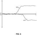
- Fig. 4 there is depicted a diagram showing the progression of relative levels of duct clogging, ⁇ DC, for two milk ducts of a subject, 410 and 420 respectively.
- a sigmoid-shaped curve or step function can be used to identify the duct prone to clogging. For instance, after ⁇ DC for duct 420 has moved or stepped significantly away from 0, this may indicate that the duct is prone to clogging.
- the method 300 may further comprise the step (not shown) of generating a display control signal, the display control signal describing the determined risk.
- the display control signal may comprise feedback that the nipple most recently measured is clogged or at risk of clogging.
- the display control signal may comprise feedback indicating an area at which a milk blocked duct has been identified. This may enable the subject to take corrective curative action.
- the display control signal may comprise a presentation of a graph indicative of a MER cycle of the subject.
- the display control signal may comprise a graph indicative of a change of a calibrated duct parameter value over time, for instance, over several weeks.
- scanned image stacks at the moment of MER may be analysed to detect abnormal duct dilation behind a blocked duct.
- measurements for a single duct are calibrated, and the duct parameter values are determined at varying locations along the duct.
- single duct calibration is performed at a varying location, x, along a single duct at either a fixed time point, t, or as a function of time.
- either one image at the moment of MER is used, or a sequence of laterally or vertically scanned images at the moment of MER.
- FIG. 6 there is depicted a diagram showing dilation of a duct lumen 640 behind a clogged duct 645.
- a breast 610 of a subject There is shown a breast 610 of a subject, and two ducts, 635 and 645, within a nipple 620.
- the duct 635 is not blocked and therefore the duct lumen 630 of this duct is not dilated.
- the duct 645 is blocked therefore leading to a dilation of the duct lumen 640.
- a position along the duct lumens from the surface of the nipple into the breast 610 can be defined along axis x.
- equation 5 can be re-written as: D 2 MER 1 , x 3 , t D 2 ME R 1 , x 3,1
- Equation 6 may thus be used to monitor/identify abnormal duct dilation over time, and may be plotted as in Fig. 4 .
- equation 5 or 6 should therefore preferably be monitored for a range of positions, x i , with i being the index number of a certain position.
- a blockage may then be detected if a maximum value of equation 5 or 6 for a range of positions exceeds a threshold. For example, a blockage may be detected using the following equation: MAX xi DPV MER 1 , xi , t DPV MER 1 , xi , t > threshold
- Equation 7 is therefore simply stating that if a maximum value of equation 5 along x exceeds a threshold, then this may indicate a blockage.
- a maximum one may look at a certain highest percentile of equations 5 or 6 for a range of positions exceeding a threshold. For example, if 10% of equations 5 or 6 for a range of positions exceed a threshold, or if the standard division of equations 5 or 6 for a range of positions exceeds a threshold. This may then provide a more robust assessment than just considering one maximum value.
- This embodiment thus provides an advantageous method for determining possible duct clogging by greatly reducing the relevant image data volume needed to analysis, i.e. only analysing images taken at the moment of MER.
- a computer program comprising code means for implementing any of the methods described above when said program is run on a processing system.
- FIG. 7 there is depicted a simplified block diagram of a system 700 for calibrating a duct parameter measurement of a milk duct of a subject according to a proposed embodiment.
- the system 700 is configured to calibrate a duct parameter measurement of a milk duct of a subject by processing detected milk ejection reflex parameter values and determined duct parameter values of a milk duct of the subject.
- the optical imaging unit 710 is configured to obtain measurements of the at least one MER cycle of the subject, wherein detecting the at least one MER parameter value is based on the obtained measurements. It is not essential that the system 700 have an optical imaging unit 710, as the system 700 may receive information about at least one MER cycle of the subject from a stand-alone unit, such as a stand-alone optical imaging unit or from a bottle unit that, for example, monitors the rate of filling. However, integrating an optical imaging unit 710 into the system 700 may provide a comprehensive system 700 capable of carrying out any herein disclosed method, such as method 100 or method 300.
- the optical imaging unit 710 may be rotatable and configured to perform a scan of different imaging directions. This may enable a more complete 3D image of a milk duct to be formed.
- the light source for the optical imaging unit 710 may comprise a near infra red light source. Infra red light may have sufficiently low scattering and absorption to penetrate the nipple fully. Based on scattering differences between milk and tissue a visual contrast between ducts and the surrounding tissue is obtained. Specific wavelengths may be chosen which have a difference in absorption between the milk and the breast/nipple tissue, for example using absorption of fatty acids in milk or other milk specific components.
- the optical imaging unit 710 may provide images of a nipple of the subject and, optionally, also a portion of the breast behind the nipple or areola.
- the processor arrangement 720 is configured to: detect at least one milk ejection reflect (MER) parameter value of at least one MER cycle of the subject; determine at least one duct parameter value of a milk duct of the subject; and calibrate the determined at least one duct parameter value based on the detected at least one MER parameter value to generate at least one calibrated duct parameter value.
- MER milk ejection reflect
- FIG. 8 there is depicted a simplified block diagram of a breast pump 800 comprising a system 700 for calibrating a duct parameter measurement of a milk duct of a subject according to a proposed embodiment.
- a breast pump 800 (not shown in detail) is thereby provided that is capable of optically imaging milk ducts of subjects to obtain measurements and also capable of analysing the measurements to calibrate them and potentially determine a risk of clogging.
- the breast pump is not shown since no further modification is needed to a standard breast pump design.
- the breast pump may be wearable or it may be external.
- the system 700 of Fig. 7 may be built into already existing devices or products used by breastfeeding mother, such as a standard breast pump, wearable breast pump or a nipple shield. This has the advantage that in all cases a fluctuating pressure cycle is already present (generated by the breast pump or by the baby sucking) and the mother does not need to spend any additional time performing the detection.
- Tracking duct geometry over time can additionally be a powerful way to decide whether a duct is blocked.
- Each duct will have its own diameter and diameter fluctuation pattern and also have different unique features such as location in the breast, widening and narrowing patterns, branching patterns etc. Therefore, individual ducts may be recognized and followed over time. If the dynamic movement of a particular duct significantly drops, this may indicate (partial) blockage, and the mother may be alerted to treat it.
- An algorithm may be utilized capable of learning features, such as a neural network, to improve recognition of individual ducts.
- a feedback system may also be provided indicating the areas to which attention is needed, so the mother can for example focus on this area by changing position of breastfeeding, feeding more frequently etc.
- This may be implemented as a wireless communication to a subject's device such as a smart phone, to provide a report which includes a graphical representation of the breast so that the area of blocked milk duct can be identified.
- alarm features such that the device automatically sends messages, blinking lights or certain sounds etc., to alarm the breastfeeding mother if clogged ducts are detected.
- any herein disclosed processing does not need to be in real time. Images can for example be stored and analyzed after the breast pumping or breast feeding event, and the output may be given a short time afterwards. However, real time processing is also possible.
- Fig. 9 illustrates an example of a computer 900 within which one or more parts of an embodiment may be employed.
- Various operations discussed above may utilize the capabilities of the computer 900.
- system functional blocks can run on a single computer or may be distributed over several computers and locations (e.g. connected via internet).
- the computer 900 includes, but is not limited to, PCs, workstations, laptops, PDAs, palm devices, servers, storages, and the like.
- the computer 900 may include one or more processors 910, memory 920 and one or more I/O devices 930 that are communicatively coupled via a local interface (not shown).
- the local interface can be, for example but not limited to, one or more buses or other wired or wireless connections, as is known in the art.
- the local interface may have additional elements, such as controllers, buffers (caches), drivers, repeaters, and receivers, to enable communications. Further, the local interface may include address, control, and/or data connections to enable appropriate communications among the aforementioned components.
- the processor 910 is a hardware device for executing software that can be stored in the memory 920.
- the processor 910 can be virtually any custom made or commercially available processor, a central processing unit (CPU), a digital signal processor (DSP), or an auxiliary processor among several processors associated with the computer 900, and the processor 910 may be a semiconductor based microprocessor (in the form of a microchip) or a microprocessor.
- the memory 920 can include any one or combination of volatile memory elements (e.g., random access memory (RAM), such as dynamic random access memory (DRAM), static random access memory (SRAM), etc.) and non-volatile memory elements (e.g., ROM, erasable programmable read only memory (EPROM), electronically erasable programmable read only memory (EEPROM), programmable read only memory (PROM), tape, compact disc read only memory (CD-ROM), disk, diskette, cartridge, cassette or the like, etc.).
- RAM random access memory
- DRAM dynamic random access memory
- SRAM static random access memory
- non-volatile memory elements e.g., ROM, erasable programmable read only memory (EPROM), electronically erasable programmable read only memory (EEPROM), programmable read only memory (PROM), tape, compact disc read only memory (CD-ROM), disk, diskette, cartridge, cassette or the like, etc.
- ROM read only memory
- EPROM erasable programmable read
- the software in the memory 920 may include one or more separate programs, each of which comprises an ordered listing of executable instructions for implementing logical functions.
- the software in the memory 920 includes a suitable operating system (O/S) 950, compiler 960, source code 970, and one or more applications 980 in accordance with exemplary embodiments.
- the application 980 comprises numerous functional components for implementing the features and operations of the exemplary embodiments.
- the application 980 of the computer 900 may represent various applications, computational units, logic, functional units, processes, operations, virtual entities, and/or modules in accordance with exemplary embodiments, but the application 980 is not meant to be a limitation.
- the operating system 950 controls the execution of other computer programs, and provides scheduling, input-output control, file and data management, memory management, and communication control and related services. It is contemplated by the inventors that the application 980 for implementing exemplary embodiments may be applicable on all commercially available operating systems.
- Application 980 may be a source program, executable program (object code), script, or any other entity comprising a set of instructions to be performed.
- a source program then the program is usually translated via a compiler (such as the compiler 960), assembler, interpreter, or the like, which may or may not be included within the memory 920, so as to operate properly in connection with the O/S 950.
- the application 980 can be written as an object oriented programming language, which has classes of data and methods, or a procedure programming language, which has routines, subroutines, and/or functions, for example but not limited to, C, C++, C#, Pascal, Python, BASIC, API calls, HTML, XHTML, XML, ASP scripts, JavaScript, FORTRAN, COBOL, Perl, Java, ADA, .NET, and the like.
- the I/O devices 930 may include input devices such as, for example but not limited to, a mouse, keyboard, scanner, microphone, camera, etc. Furthermore, the I/O devices 930 may also include output devices, for example but not limited to a printer, display, etc. Finally, the I/O devices 930 may further include devices that communicate both inputs and outputs, for instance but not limited to, a NIC or modulator/demodulator (for accessing remote devices, other files, devices, systems, or a network), a radio frequency (RF) or other transceiver, a telephonic interface, a bridge, a router, etc. The I/O devices 930 also include components for communicating over various networks, such as the Internet or intranet.
- a NIC or modulator/demodulator for accessing remote devices, other files, devices, systems, or a network
- RF radio frequency
- the I/O devices 930 also include components for communicating over various networks, such as the Internet or intranet.
- the software in the memory 920 may further include a basic input output system (BIOS) (omitted for simplicity).
- BIOS is a set of essential software routines that initialize and test hardware at start-up, start the O/S 950, and support the transfer of data among the hardware devices.
- the BIOS is stored in some type of read-only-memory, such as ROM, PROM, EPROM, EEPROM or the like, so that the BIOS can be executed when the computer 800 is activated.
- the processor 910 When the computer 900 is in operation, the processor 910 is configured to execute software stored within the memory 920, to communicate data to and from the memory 920, and to generally control operations of the computer 900 pursuant to the software.
- the application 980 and the O/S 950 are read, in whole or in part, by the processor 910, perhaps buffered within the processor 910, and then executed.
- a computer readable medium may be an electronic, magnetic, optical, or other physical device or means that can contain or store a computer program for use by or in connection with a computer related system or method.
- the application 980 can be embodied in any computer-readable medium for use by or in connection with an instruction execution system, apparatus, or device, such as a computer-based system, processor-containing system, or other system that can fetch the instructions from the instruction execution system, apparatus, or device and execute the instructions.
- a "computer-readable medium" can be any means that can store, communicate, propagate, or transport the program for use by or in connection with the instruction execution system, apparatus, or device.
- the computer readable medium can be, for example but not limited to, an electronic, magnetic, optical, electromagnetic, infrared, or semiconductor system, apparatus, device, or propagation medium.
- Figs. 1 and 3 may be implemented in hardware or software, or a mixture of both (for example, as firmware running on a hardware device).
- the functional steps illustrated in the process flowcharts may be performed by suitably programmed physical computing devices, such as one or more central processing units (CPUs) or graphics processing units (GPUs).
- CPUs central processing units
- GPUs graphics processing units
- Each process - and its individual component steps as illustrated in the flowcharts - may be performed by the same or different computing devices.
- a computer-readable storage medium stores a computer program comprising computer program code configured to cause one or more physical computing devices to carry out an encoding or decoding method as described above when the program is run on the one or more physical computing devices.
- Storage media may include volatile and non-volatile computer memory such as RAM, PROM, EPROM, and EEPROM, optical discs (like CD, DVD, BD), magnetic storage media (like hard discs and tapes).
- RAM random access memory
- PROM read-only memory
- EPROM erasable programmable read-only memory
- EEPROM electrically erasable programmable read-only memory
- optical discs like CD, DVD, BD
- magnetic storage media like hard discs and tapes.
- Various storage media may be fixed within a computing device or may be transportable, such that the one or more programs stored thereon can be loaded into a processor.
- the blocks shown in the block diagrams of Figs. 7 or 8 may be separate physical components, or logical subdivisions of single physical components, or may be all implemented in an integrated manner in one physical component.
- the functions of one block shown in the drawings may be divided between multiple components in an implementation, or the functions of multiple blocks shown in the drawings may be combined in single components in an implementation.
- Hardware components suitable for use in embodiments of the present invention include, but are not limited to, conventional microprocessors, application specific integrated circuits (ASICs), and field-programmable gate arrays (FPGAs).
- ASICs application specific integrated circuits
- FPGAs field-programmable gate arrays
- One or more blocks may be implemented as a combination of dedicated hardware to perform some functions and one or more programmed microprocessors and associated circuitry to perform other functions.
- a computer program may be stored/distributed on a suitable medium, such as an optical storage medium or a solid-state medium supplied together with or as part of other hardware, but may also be distributed in other forms, such as via the Internet or other wired or wireless telecommunication systems.
- a suitable medium such as an optical storage medium or a solid-state medium supplied together with or as part of other hardware, but may also be distributed in other forms, such as via the Internet or other wired or wireless telecommunication systems.
- each block in the flowchart or block diagrams may represent a module, segment, or portion of instructions, which comprises one or more executable instructions for implementing the specified logical function(s).
- the functions noted in the block may occur out of the order noted in the figures.
- two blocks shown in succession may, in fact, be executed substantially concurrently, or the blocks may sometimes be executed in the reverse order, depending upon the functionality involved.
- each block of the block diagrams and/or flowchart illustration, and combinations of blocks in the block diagrams and/or flowchart illustration can be implemented by special purpose hardware-based systems that perform the specified functions or acts or carry out combinations of special purpose hardware and computer instructions, the architecture, functionality, and operation of possible implementations of systems, methods, and computer program products according to various embodiments of the present invention.
- each block in the flowchart or block diagrams may represent a module, segment, or portion of instructions, which comprises one or more executable instructions for implementing the specified logical function(s).
- the functions noted in the block may occur out of the order noted in the figures.
Landscapes
- Health & Medical Sciences (AREA)
- Life Sciences & Earth Sciences (AREA)
- Physics & Mathematics (AREA)
- Heart & Thoracic Surgery (AREA)
- Animal Behavior & Ethology (AREA)
- Biomedical Technology (AREA)
- Engineering & Computer Science (AREA)
- General Health & Medical Sciences (AREA)
- Public Health (AREA)
- Veterinary Medicine (AREA)
- Molecular Biology (AREA)
- Medical Informatics (AREA)
- Pathology (AREA)
- Surgery (AREA)
- Biophysics (AREA)
- Fluid Mechanics (AREA)
- General Physics & Mathematics (AREA)
- Gynecology & Obstetrics (AREA)
- Vascular Medicine (AREA)
- Hematology (AREA)
- Reproductive Health (AREA)
- Pediatric Medicine (AREA)
- Anesthesiology (AREA)
- Electromagnetism (AREA)
- Endocrinology (AREA)
- Gastroenterology & Hepatology (AREA)
- Physiology (AREA)
- External Artificial Organs (AREA)
- Measuring Pulse, Heart Rate, Blood Pressure Or Blood Flow (AREA)
- Measuring And Recording Apparatus For Diagnosis (AREA)
Priority Applications (3)
| Application Number | Priority Date | Filing Date | Title |
|---|---|---|---|
| EP23163671.3A EP4434443A1 (fr) | 2023-03-23 | 2023-03-23 | Étalonnage de mesures de paramètres de conduit |
| PCT/EP2024/055532 WO2024193994A1 (fr) | 2023-03-23 | 2024-03-04 | Normalisation de mesures de paramètres de canal |
| CN202410329398.7A CN118680516A (zh) | 2023-03-23 | 2024-03-21 | 标准化导管参数测量结果 |
Applications Claiming Priority (1)
| Application Number | Priority Date | Filing Date | Title |
|---|---|---|---|
| EP23163671.3A EP4434443A1 (fr) | 2023-03-23 | 2023-03-23 | Étalonnage de mesures de paramètres de conduit |
Publications (1)
| Publication Number | Publication Date |
|---|---|
| EP4434443A1 true EP4434443A1 (fr) | 2024-09-25 |
Family
ID=85726402
Family Applications (1)
| Application Number | Title | Priority Date | Filing Date |
|---|---|---|---|
| EP23163671.3A Withdrawn EP4434443A1 (fr) | 2023-03-23 | 2023-03-23 | Étalonnage de mesures de paramètres de conduit |
Country Status (3)
| Country | Link |
|---|---|
| EP (1) | EP4434443A1 (fr) |
| CN (1) | CN118680516A (fr) |
| WO (1) | WO2024193994A1 (fr) |
Citations (2)
| Publication number | Priority date | Publication date | Assignee | Title |
|---|---|---|---|---|
| EP1827210A1 (fr) * | 2004-11-18 | 2007-09-05 | Mamsense Ltd. | Appareil et procédé de mesure de débit de lait maternel |
| EP3827737A1 (fr) * | 2019-11-26 | 2021-06-02 | Koninklijke Philips N.V. | Système et procédé de surveillance pour surveiller l'écoulement de lait pendant l'allaitement maternel ou l'expression du lait |
-
2023
- 2023-03-23 EP EP23163671.3A patent/EP4434443A1/fr not_active Withdrawn
-
2024
- 2024-03-04 WO PCT/EP2024/055532 patent/WO2024193994A1/fr not_active Ceased
- 2024-03-21 CN CN202410329398.7A patent/CN118680516A/zh active Pending
Patent Citations (2)
| Publication number | Priority date | Publication date | Assignee | Title |
|---|---|---|---|---|
| EP1827210A1 (fr) * | 2004-11-18 | 2007-09-05 | Mamsense Ltd. | Appareil et procédé de mesure de débit de lait maternel |
| EP3827737A1 (fr) * | 2019-11-26 | 2021-06-02 | Koninklijke Philips N.V. | Système et procédé de surveillance pour surveiller l'écoulement de lait pendant l'allaitement maternel ou l'expression du lait |
Also Published As
| Publication number | Publication date |
|---|---|
| CN118680516A (zh) | 2024-09-24 |
| WO2024193994A1 (fr) | 2024-09-26 |
Similar Documents
| Publication | Publication Date | Title |
|---|---|---|
| CN114096993B (zh) | 图像分割置信度确定 | |
| CN102262709B (zh) | 用于患者监测的告警生成方法和生理监测设备 | |
| CN105765584A (zh) | 基于临床决策支持系统的分诊决策制定 | |
| CN109036500A (zh) | 一种临床预警方法、装置、设备及存储介质 | |
| CN120078431B (zh) | 一种麻醉过程中的生命体征监测系统及方法 | |
| CN119314606A (zh) | 一种基于picc导管实时数据采集的护理质量监控系统 | |
| EP4434443A1 (fr) | Étalonnage de mesures de paramètres de conduit | |
| US20260041324A1 (en) | Assessment Method of Vascular Function in Dialysis Patient and System Thereof | |
| KR20240110047A (ko) | 인공 지능을 이용한 직접 의학적 치료법 예측 | |
| US11607145B2 (en) | Techniques for determining characteristics of dialysis access sites using image information | |
| US8050748B2 (en) | Decision support system to detect the presence of artifacts in patients monitoring signals using morphograms | |
| CN116392212B (zh) | 一种穿刺针脱落预警方法、装置、可穿戴设备及存储介质 | |
| CN112716525B (zh) | 胎儿心率的处理方法、装置及可读存储介质 | |
| US20230113324A1 (en) | Medical information processing device, medical information processing method, and storage medium | |
| KR101716667B1 (ko) | 피하 혈관의 혈류량 변화를 측정하는 방법 및 장치 | |
| CN117017249B (zh) | 血压检测装置 | |
| JP7737691B2 (ja) | 異常検出装置 | |
| JP7440665B2 (ja) | 網膜画像処理 | |
| WO2022076776A1 (fr) | Techniques pour déterminer des caractéristiques de sites d'accès pour dialyse à l'aide d'informations d'image | |
| CN120616487A (zh) | 一种基于脑血流自动调节算法的脑部疾病预警方法及系统 | |
| CN120613124A (zh) | 一种基于糖尿病患者的智能病程管理方法及其系统 | |
| CN120860369A (zh) | 一种基于数字化技术的静脉注射泵液体流动状态控制仪器 | |
| CN119969989A (zh) | 一种颅内压检测方法及装置 | |
| KR20160109474A (ko) | 피하 혈관의 혈류량 변화를 측정하는 방법 및 장치 | |
| CN116019561A (zh) | 一种心脑血管介入手术机器人及其导丝导管推送方法 |
Legal Events
| Date | Code | Title | Description |
|---|---|---|---|
| PUAI | Public reference made under article 153(3) epc to a published international application that has entered the european phase |
Free format text: ORIGINAL CODE: 0009012 |
|
| STAA | Information on the status of an ep patent application or granted ep patent |
Free format text: STATUS: THE APPLICATION HAS BEEN PUBLISHED |
|
| AK | Designated contracting states |
Kind code of ref document: A1 Designated state(s): AL AT BE BG CH CY CZ DE DK EE ES FI FR GB GR HR HU IE IS IT LI LT LU LV MC ME MK MT NL NO PL PT RO RS SE SI SK SM TR |
|
| STAA | Information on the status of an ep patent application or granted ep patent |
Free format text: STATUS: THE APPLICATION IS DEEMED TO BE WITHDRAWN |
|
| 18D | Application deemed to be withdrawn |
Effective date: 20250326 |