EP4434613A1 - Herstellung von membranen durch kombinierte verdampfungs- und fällungsmittelinduzierte phasentrennung - Google Patents
Herstellung von membranen durch kombinierte verdampfungs- und fällungsmittelinduzierte phasentrennung Download PDFInfo
- Publication number
- EP4434613A1 EP4434613A1 EP23163526.9A EP23163526A EP4434613A1 EP 4434613 A1 EP4434613 A1 EP 4434613A1 EP 23163526 A EP23163526 A EP 23163526A EP 4434613 A1 EP4434613 A1 EP 4434613A1
- Authority
- EP
- European Patent Office
- Prior art keywords
- membrane
- polymer
- volatile solvent
- body portion
- solvent
- Prior art date
- Legal status (The legal status is an assumption and is not a legal conclusion. Google has not performed a legal analysis and makes no representation as to the accuracy of the status listed.)
- Withdrawn
Links
Images


Classifications
-
- B—PERFORMING OPERATIONS; TRANSPORTING
- B01—PHYSICAL OR CHEMICAL PROCESSES OR APPARATUS IN GENERAL
- B01D—SEPARATION
- B01D67/00—Processes specially adapted for manufacturing semi-permeable membranes for separation processes or apparatus
- B01D67/0002—Organic membrane manufacture
- B01D67/0009—Organic membrane manufacture by phase separation, sol-gel transition, evaporation or solvent quenching
- B01D67/00091—Organic membrane manufacture by phase separation, sol-gel transition, evaporation or solvent quenching by evaporation
-
- B—PERFORMING OPERATIONS; TRANSPORTING
- B01—PHYSICAL OR CHEMICAL PROCESSES OR APPARATUS IN GENERAL
- B01D—SEPARATION
- B01D61/00—Processes of separation using semi-permeable membranes, e.g. dialysis, osmosis or ultrafiltration; Apparatus, accessories or auxiliary operations specially adapted therefor
- B01D61/14—Ultrafiltration; Microfiltration
- B01D61/145—Ultrafiltration
-
- B—PERFORMING OPERATIONS; TRANSPORTING
- B01—PHYSICAL OR CHEMICAL PROCESSES OR APPARATUS IN GENERAL
- B01D—SEPARATION
- B01D67/00—Processes specially adapted for manufacturing semi-permeable membranes for separation processes or apparatus
- B01D67/0002—Organic membrane manufacture
- B01D67/0009—Organic membrane manufacture by phase separation, sol-gel transition, evaporation or solvent quenching
- B01D67/0011—Casting solutions therefor
-
- B—PERFORMING OPERATIONS; TRANSPORTING
- B01—PHYSICAL OR CHEMICAL PROCESSES OR APPARATUS IN GENERAL
- B01D—SEPARATION
- B01D67/00—Processes specially adapted for manufacturing semi-permeable membranes for separation processes or apparatus
- B01D67/0002—Organic membrane manufacture
- B01D67/0009—Organic membrane manufacture by phase separation, sol-gel transition, evaporation or solvent quenching
- B01D67/0013—Casting processes
- B01D67/00135—Air gap characteristics
-
- B—PERFORMING OPERATIONS; TRANSPORTING
- B01—PHYSICAL OR CHEMICAL PROCESSES OR APPARATUS IN GENERAL
- B01D—SEPARATION
- B01D71/00—Semi-permeable membranes for separation processes or apparatus characterised by the material; Manufacturing processes specially adapted therefor
- B01D71/06—Organic material
- B01D71/08—Polysaccharides
- B01D71/12—Cellulose derivatives
- B01D71/14—Esters of organic acids
- B01D71/16—Cellulose acetate
-
- B—PERFORMING OPERATIONS; TRANSPORTING
- B01—PHYSICAL OR CHEMICAL PROCESSES OR APPARATUS IN GENERAL
- B01D—SEPARATION
- B01D71/00—Semi-permeable membranes for separation processes or apparatus characterised by the material; Manufacturing processes specially adapted therefor
- B01D71/06—Organic material
- B01D71/08—Polysaccharides
- B01D71/12—Cellulose derivatives
- B01D71/22—Cellulose ethers
-
- B—PERFORMING OPERATIONS; TRANSPORTING
- B01—PHYSICAL OR CHEMICAL PROCESSES OR APPARATUS IN GENERAL
- B01D—SEPARATION
- B01D71/00—Semi-permeable membranes for separation processes or apparatus characterised by the material; Manufacturing processes specially adapted therefor
- B01D71/06—Organic material
- B01D71/66—Polymers having sulfur in the main chain, with or without nitrogen, oxygen or carbon only
- B01D71/68—Polysulfones; Polyethersulfones
-
- B—PERFORMING OPERATIONS; TRANSPORTING
- B01—PHYSICAL OR CHEMICAL PROCESSES OR APPARATUS IN GENERAL
- B01D—SEPARATION
- B01D2323/00—Details relating to membrane preparation
-
- B—PERFORMING OPERATIONS; TRANSPORTING
- B01—PHYSICAL OR CHEMICAL PROCESSES OR APPARATUS IN GENERAL
- B01D—SEPARATION
- B01D2323/00—Details relating to membrane preparation
- B01D2323/219—Specific solvent system
-
- B—PERFORMING OPERATIONS; TRANSPORTING
- B01—PHYSICAL OR CHEMICAL PROCESSES OR APPARATUS IN GENERAL
- B01D—SEPARATION
- B01D2323/00—Details relating to membrane preparation
- B01D2323/219—Specific solvent system
- B01D2323/22—Specific non-solvents or non-solvent system
-
- B—PERFORMING OPERATIONS; TRANSPORTING
- B01—PHYSICAL OR CHEMICAL PROCESSES OR APPARATUS IN GENERAL
- B01D—SEPARATION
- B01D2325/00—Details relating to properties of membranes
- B01D2325/02—Details relating to pores or porosity of the membranes
- B01D2325/022—Asymmetric membranes
Definitions
- the present invention relates to an ultrafiltration membrane and to a method for producing the same.
- Ultrafiltration membranes are in general characterized by very narrow pore sizes between 2 - 100 nm ( Terminology for membranes and membrane processes. In: Journal of Membrane Science, 120, 149-159, 1996 .) and are used for separation/purification processes on a molecular level. In terms of the retentive properties of the membranes, a similar definition may be made on the basis of the molecular weight cut-off (MWCO).
- MWCO molecular weight cut-off
- the MWCO relates to the dissolved compound (generally dextrans) having the lowest molecular weight, in daltons, for which a fraction of 90% of the dissolved compound is retained by the membrane, or alternatively to the molecular weight of the molecule, in daltons, for which a fraction of 90% of the molecules having this molecular weight is retained by the membrane.
- a membrane having an MWCO of 10 kDa retains dextrans of 10 kDa and larger to an extent of at least 90%.
- Common operations, which are performed via ultrafiltration are the concentration of target molecules, buffer exchange or elimination of impurities by size exclusion.
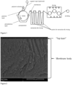
- the production of ultrafiltration membranes is commonly achieved by a process scheme as schematically shown in Figure 1 .
- Said process scheme involves producing a solution of the membrane-forming polymer in a suitable solvent which may include further additives if needed (hydrophilizing or pore forming agents), casting the solution in a defined thickness on a suitable carrier (endless steel belt, steel drum), transporting the solution film into a non-solvent bath to induce the phase separation process, and extracting, washing, drying, and winding of the formed membrane film.
- the membrane can be mainly characterized by its permeability P and rejection R profile.
- P and rejection R profile In general, it is desired to produce a membrane with a very high permeability at a given rejection profile. This leads to faster processing in nearly all unit operations while maintaining the needed separation efficiency.
- Permeability and rejection are determined by different structural properties of the membrane.
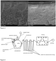
- the rejection is determined by the size of the smallest pores in the membrane. For ultrafiltration membranes, these are located at the top layer (cf. Figure 2 ).
- the permeability is determined by the pore size (gradient) in the whole membrane. High permeabilities at a given rejection profile can especially be achieved by a membrane with a high degree of asymmetry having small pores in the desired range at the membrane top layer followed by a steep gradient to larger pores to the bottom layer.
- the pore size at the top layer as well as the pore size gradient can be tailored by the properties of the polymer solution and the membrane production process to a certain extent. This can be used to improve the ratio of rejection to permeability to achieve more desirable membrane properties. Examples of ultrafiltration membranes showing a similar rejection profile but a different permeability due to differences in the pore size gradient are illustrated in Figure 3 . Using the common approach of membrane formation as shown in Figure 1 , the achievable ratio of rejection to permeability is, however, limited by the thermodynamic and kinetic aspects of the membrane formation itself.
- the pore size at each position within the membrane is determined by the polymer content in the casting solution at the onset of phase separation as well as the coalescence time between the onset of phase separation and the solidification of the membrane body. Therefore, a feasible approach to achieve small pores at the membrane top layer as well as larger pores in the membrane body is to use two layered polymer solutions for membrane formation, namely a thin layer of a solution containing a high amount of polymer to form the top layer as well as a larger layer of a solution containing low amount of polymer to form larger pores in the membrane body. This approach, however, is laborious as it needs a precise control of layer thickness as well as twice the amount of mixing, pumping and layering technology.
- the technical problem underlying the present invention is to provide an ultrafiltration membrane which has an improved ratio of rejection to permeability in an efficient and fast way.
- the present invention relates to a method for producing an ultrafiltration membrane, comprising the steps of:
- an ultrafiltration membrane is obtainable that achieves superior ratios of rejection to permeability by applying a single layer approach combining precipitant-induced phase separation and evaporation-induced phase separation.
- This is achieved by using a combination of solvents in the polymer solution.
- One solvent is highly volatile (i.e. high volatile solvent) while the other solvent is hardly volatile (i.e. low volatile solvent).
- the membrane formation process includes an additional evaporation zone, where the high volatile solvent evaporates from only the top portion of the polymer solution film.
- the process is schematically illustrated in Figure 4 .
- the method of the present invention comprises only one polymer solution application step and, thus, besides step (b) no further polymer solution application steps.
- No additional machine equipment is preferably needed compared to common approaches.
- no toxic solvents or other substances of very high concern are used.
- Reduction of production cost due to the new process design is preferably possible.
- a simple control of critical process parameters is preferably possible.
- the partial evaporation of the high volatile solvent leads to a higher polymer concentration near the membrane top portion.
- the structure finalization during the precipitation step leads to a conservation of this characteristic and consequently to a more asymmetric membrane structure. This yields to rejection rates at higher membrane permeability enabling faster separation processes.
- ultrafiltration membrane refers to a membrane having an MWCO of 1 kDa to 1000 kDa.
- the determination of the molecular weight cut-off can be carried out in accordance with the US standard ASTM E1343-90 ("Standard test method for molecular weight cutoff evaluation of flat sheet ultrafiltration membranes").
- capillary flow porometry is used to determine the pore size.
- This is a gas/liquid porosimetry in which the differential gas pressures and flow rates through a membrane sample are measured first in the wet and then in the dry state. Prior to measurement, the membrane sample is brought into contact with a wetting liquid in such a way that all pores are filled with this liquid. After the pores have been filled and the sample has been introduced, the measuring cell must be closed and the measurement started. After starting the measurement, the gas pressure is automatically and gradually increased and the pore diameters corresponding to the applied pressure are emptied by the gas pressure.
- the liquid-liquid displacement method which has similarities to capillary flow porometry, is used. However, instead of the gas flow rates, the flow rates of the displacing liquid are measured as a function of the differential pressure increase (see also R. Dávila, "Characterization of ultra and nanofiltration commercial filters by liquid-liquid displacement porosimetry", 2013 ). Due to complexity of the method, cut-offs are determined by filtering model substances and generating sieve curves indicating cut-off behavior of the membranes over a range of molecular weights (cf. ASTM E1343-90).
- step (a) a polymer solution comprising a polymer, a high volatile solvent, a low volatile solvent, and a non-solvent is provided. Any known means for providing a respective polymer solution can be applied.
- the polymer(s) used for producing the ultrafiltration membrane are not subject to any special restrictions. Use may therefore be made of any one or more polymers suitable for membrane formation.
- the polymers in solution in the polymer solutions can for example be polyethersulfone (PES), polysulfone, polyphenylensulfone, polyetherimide, cellulose acetate (CA), such as cellulose diacetate and cellulose triacetate, cellulose ester, and cellulose ether.
- the polymer solution may comprise one or more, preferably one, of these membrane-forming polymers.
- the membrane-forming polymers are preferably polyethersulfone and/or cellulose acetate. Most preferably, polyethersulfones are used as membrane-forming polymer(s).
- the high volatile and the low volatile solvent are not particularly limited apart from the corresponding high and low volatility, respectively.
- the term "high volatility" means that the respective substance has a boiling temperature of less than 100°C at 1013 hPa and a vapor pressure of at least 50 hPa at 20°C.
- a high volatile solvent has a boiling point (bp) of less than 100°C at 1013 hPa and a vapor pressure of at least 50 hPa at 20°C (vp).
- a low volatile solvent has a boiling point of at least 100°C at 1013 hPa and a vapor pressure of less than 50 hPa at 20°C (see also DIN 53170).
- the high and low volatile solvents are both preferably mixable with the precipitation bath liquid. In particular the high and low volatile solvents are preferable mixable with water in case of an aqueous precipitation bath.
- Examples of the high volatile solvent are acetone (bp 56°C, vp 246 hPa), formaldehyde (bp -19°C, vp 4400 hPa), tetrahydrofuran (bp 65°C, vp 170 hPa), methyl acetate (bp 57°C, vp 228 hPa), methyl ethyl ketone (bp 80°C, vp 105 hPa), methyl formate (bp 32°C, vp 638 hPa), and ethyl formate (bp 54°C, vp 266 hPa).
- Boiling points (bp) at 1013 hPa and vapor pressures (vp) at 20°C are given in parentheses.
- the high volatile solvent is selected from the group consisting of acetone, methyl acetate, methyl formate, and ethyl formate. Said solvents can be used alone or in any combination. Preferably, one high volatile solvent is used. High volatile solvents, such as acetone, methyl acetate, methyl formate, ethyl formate, and tetrahydrofuran, are beneficial, due to their low viscosity leading to lower viscosities of the casting solution/polymer solution, which results to an improved processibility compared to casting solutions with higher viscosities (and same amount of solid).
- the low volatile solvent can for example be 2-pyrrolidone (bp 245°C, vp 0.04 hPa), N-methyl-2-pyrrolidone (bp 203°C, 0.32 hPa), N-n-butyl-2-pyrrolidone (bp 240.6 °C, vp 0.13 hPa, SDS Carl Roth), dimethylacetamide (bp 165°C,vp 3.3 hPa), 2-hydroxy-N,N-dimethylpropanamide (bp at least 224°C at 1031 hPa, vp 0.12 hPa or less, SDS Sigma Aldrich ), dihydrolevoglucosenone (bp 227°C at 1007 hPa, vp 0.28 hPa at 25°C, SDS Sigma Aldrich ), DMSO (bp 189°C, vp 0.556 hPa), and DMF (bp 153°C, vp 3.77 h
- the low volatile solvent is selected from the group consisting of 2-pyrrolidone, N-n-butyl-2-pyrrolidone, dihydrolevoglucosenone, and 2-hydroxy-N,N-dimethylpropanamide. Said solvents can be used alone or in any combination. Preferably, one low volatile solvent is used.
- non REACH solvents such as 2-pyrrolidone, N-n-butyl-2-pyrrolidone, 2-hydroxy-N,N-dimethylpropanamide, and dihydrolevoglucosenone it is advantageously possible to obtain a membrane with content of REACH materials below detectable limits or with no REACH materials.
- REACH is a European regulation, which aims to improve the protection of human health and the environment from the risks that can be posed by chemicals. On basis of this regulation by ECHA (European Chemical Agency) the production and/or use of certain substances is forbidden in the European Union or strictly limited. Some substances are prone to be or most likely to be forbidden. These “candidates” are also unfavorable for use.
- REACH materials refers to both types of materials, already forbidden ones as well as potential candidates.
- non REACH implies the beneficial state of a substance (solvent) not being registered as material of concern.
- Examples of current beneficial solvents are acetic acid, acetone, N-n-butyl-2-pyrrolidone, dihydrolevoglucosenone, ethanol, isopropanol, ethyl formate, glycerol, glycerol-1,3-diacetate, glycerol triacetate, methyl acetate, 2-hydroxy-N,N-dimethylpropanamide, 2-pyrrolidone, 2,2-dimethyl-1,3-dioxolane-4-methanol, tetrahydrofuran, and water.
- the term "detectable content” means a content of 50 ⁇ g/mL or more, e.g. after extraction with 1 mL extraction liquid (e.g. water or ethanol) on 6 cm 2 membrane surface after 24h at a temperature of 60°C to 80°C.
- the polymer solution further comprises a non-solvent for the polymer in question.
- a non-solvent in this context refers to a liquid which is unable to dissolve the membrane-forming polymer.
- the non-solvent for the membrane-forming polymer (or each of the membrane-forming polymers) preferably has a solubility under standard conditions of (in each case) at most 1 wt%, very preferably at most 0.1 wt%.
- the polymer solution comprises a non-solvent or another precipitant for the corresponding membrane-forming polymer
- the maximum concentration of the non-solvent (or precipitant) is a concentration not sufficient to lead to precipitation of the membrane-forming polymer.
- the polymer solution consists preferably of the high volatile solvent and the low volatile solvent for the corresponding membrane-forming polymer, the corresponding membrane-forming polymer, and a non-solvent (mixture).
- non-solvents are, for example, water, glycerol, methanol, ethanol, n-propanol, and iso-propanol, as well as mixtures thereof. Unless otherwise specified, the above definitions and observations relating to non-solvents are valid analogously for all aspects of the present invention.
- the non-solvent is water.
- the polymer solution may comprise 10 to 35 wt% of the (membrane-forming) polymer, 5 to 70 wt% of the high volatile solvent, 20 to 80 wt% of the low volatile solvent, and 0.1 to 15 wt% of a non-solvent, with respect to the total mass of the polymer solution.
- the content of the high volatile solvent is preferably 5 to 60 wt%, more preferably 10 to 50 wt% with respect to the total mass of the polymer solution.
- the content of the low volatile solvent is preferably 20 to 70 wt% with respect to the total mass of the polymer solution.
- the content of the non-solvent is preferably 0.5 to 15 wt%, more preferably 1.0 to 10 wt% with respect to the total mass of the polymer solution.
- the above amounts refer to the total of the respective component.
- the polymer solution may further comprise one or more additives.
- Suitable additives are, for example, swelling agents, solubilizers, hydrophilizing agents, and/or pore formers (porogens). Respective additives are known to the skilled person and are adapted to the membrane-forming polymer.
- PEG polyethylene glycol
- PVP polyvinylpyrrolidone
- Such additives may be contained in the polymer solution in an amount of 0 to 10 wt%.
- the polymer solution consists preferably of the corresponding membrane-forming polymer, the high volatile solvent, the low volatile solvent, a non-solvent, and optionally one or more additives, preferably pore formers and/or swelling agents.
- the polymer solution does not have to be subjected to any defined thermal pretreatments - i.e., it is not necessary to utilize a thermal pretreatment for membrane/structure formation. More particularly the polymer solutions preferably do not have any lower or upper critical solution temperatures.
- step (b) the polymer solution is applied to the surface of a carrier or to a support layer to form a polymer layer on the carrier or on and/or partially or completely in the support layer.
- a carrier as shown schematically in Figure 4 .
- the polymer solution can be directly applied to the carrier.
- a casting solution can be applied directly to a freely floating, hanging or spanned support layer e.g. with a die or a falling curtain or by moving it through a compartment containing the polymer solution.
- the carrier optionally with the support layer is/are used.
- Methods of applying the polymer solution are known to the skilled person from the prior art and can be used without special limitations in the method of the present invention. Such methods are, for example, methods in which the carrier and/or the support layer is/are conveyed, for example, past a doctor blade system or a slot die, from which the corresponding polymer solution emerges. Step (b) takes place preferably using a slot die.
- the polymer solution may penetrate partially or completely into the optional support layer.
- the polymer layer may penetrate into the support layer to an extent of at least 25%, preferably at least 50%, more preferably at least 75%.
- the polymer layer penetrates into the support layer to an extent of less than 100%.
- the support layer is not particularly limited. It is possible, therefore, to use all support layers known to the skilled person from the prior art.
- the support layer may be a nonwoven web, a woven fabric or an open microfilter membrane.
- nonwoven webs are polyolefin nonwovens, such as, for example, PP/PE core-shell nonwovens, and polyester nonwovens.
- the support layer is preferably a polyolefin nonwoven or a polyolefin membrane.
- the thickness of the support layer may be, for example, from 30 to 300 ⁇ m, preferably from 50 to 250 ⁇ m, more preferably from 80 to 200 ⁇ m.
- the carrier preferably has a planar surface and is inert with respect to the substances used (e.g., polymer solution and its constituents).
- Serving preferably as carrier is a moving belt (conveyor belt) or a drum (as shown schematically in Figure 4 ), each preferably made of steel, or a plastic foil, whereby a continuous implementation of the method can be enabled.
- the carrier and/or the support layer in step (b) move(s) at a speed of 30 to 500 m/h, more particularly of 60 to 400 m/h, very preferably of 100 to 300 m/h, relative to the polymer solution during application thereof.
- the carrier and/or the support layer is/are conveyed at the above-stated speeds, for example, past a doctor blade system or a slot die for application of the polymer solution.
- the application temperature in step (b) may be from 4°C to (bp of the (lowest boiling) high volatile solvent - 20% (with respect to the bp of the (lowest boiling) high volatile solvent in °C)), more preferably from 4°C to (bp of the (lowest boiling) high volatile solvent - 25%), and most preferably from 4°C to (bp of the (lowest boiling) high volatile solvent - 30%).
- step (c) the polymer layer from step (b) (with the optional support layer) is transported through an evaporation zone for partially evaporating the high volatile solvent under a relative humidity of less than 20 %RH.
- the polymer layer (with the optional support layer) can be transported with the same carrier as used in step (b) or together with the support layer by suitable transporting means known in the art.
- the term "partially” is thereby not particularly limited. For example, at least 0.01 wt% of the high volatile solvent with respect to 100 wt% of the high volatile solvent in the (initial) polymer solution are evaporated.
- At least 0.02 wt%, more preferably at least 0.04 wt%, and/or at most 2.0 wt%, more preferably at most 0.5 wt%, of the high volatile solvent with respect to 100 wt% of the high volatile solvent in the (initial) polymer solution are evaporated.
- the solution can be cast on a substrate and placed on a lab balance under the given conditions used for the casting process.
- the total decrease in weight can in close approximation be considered as the total amount of evaporated high volatile solvent, since vapor pressures of further components are orders of magnitude lower than the vapor pressure of the high volatile solvent.
- the extent of evaporation of the high volatile solvent can for example be controlled by the evaporation time and the temperature in step (c).
- the evaporation time in step (c) can be from 0.50 s to 1.0 min, preferably from 2.0 s to 20 s, more preferably from 5.0 s to 15 s.
- sufficient and non-excessive evaporation of the high volatile solvent is achieved, while suppressing evaporation of the low volatile solvent. This results in a firm skin structure/top portion for high retention, which however is thin enough to avoid additional resistance to the membrane.
- the temperature in step (c) may be from 4°C to (bp of the (lowest boiling) high volatile solvent - 20% (with respect to the bp of the (lowest boiling) high volatile solvent in °C)), more preferably from 4°C to (bp of the (lowest boiling) high volatile solvent - 25%), and most preferably from 4°C to (bp of the (lowest boiling) high volatile solvent - 30%).
- the application temperature in step (b) is preferably the same temperature or lower than the temperature in step (c).
- the application temperature in step (b) is lower than the temperature in step (c).
- the mentioned temperatures preferably allow preventing the formation of bubbles in the membrane film which could lead to major defects. When applying such temperatures, sufficient and non-excessive evaporation of the high volatile solvent is achieved, while suppressing evaporation of the low volatile solvent.
- the evaporation zone enables control of the atmosphere with respect to humidity, temperature and optionally air flow conditions.
- the humidity in the evaporation zone is reduced compared to the surrounding preferably to less than 20 %RH, more preferably less than 18 %RH, more preferably less than 15 %RH, more preferably less than 10 %RH, and most preferably from 0 to 5 %RH at the temperature used in step (c).
- this may allow to avoid an opposite effect (i.e. opening of the membrane at the top portion) caused by water diffusing into the membrane when compared to the present invention.
- the desired relative humidity (RH) can for example be adjusted by introducing a dry gas, preferably an inert gas such as nitrogen or carbon dioxide into the evaporation zone.
- step (d) the polymer layer from step (c) (with the optional support layer) is introduced into a precipitation bath which comprises a precipitant, relative to the polymer in the polymer layer/solution (as shown schematically in Figure 4 ).
- the precipitant used in step (d) is not subject to any special limitation.
- the same precipitants may be used as in conventional production methods for polymer membranes.
- the precipitant results in precipitation (phase inversion) of the membrane-forming polymer in the polymer layer.
- the precipitant may be a single compound or a mixture of two or more compounds.
- the precipitant is preferably present in a liquid, more preferably, in the precipitation bath, the precipitant is itself a liquid or the precipitation bath consists of the precipitant.
- the precipitant is preferably a non-solvent for the membrane-forming polymer(s) with the precipitation bath preferably consisting of a precipitant selected from the group consisting of water, alcohols and additized water. More preferably, the precipitation bath consists of water as the precipitant.
- the precipitant may be the same as the non-solvent contained in the polymer solution.
- the temperature of the precipitation bath is not subject to any special restrictions.
- the temperature of the precipitation bath may be from 1°C to 60°C, preferably from 3°C to 30°C, more preferably from 4°C to 20°C.
- the method of the present invention may further comprise a step of
- the polymer solution may comprise a cellulose compound such as cellulose acetate or cellulose ester.
- the method of the invention (comprising the steps of (a) - (d) or (a) - (e)) may further comprise a step of
- step (f) The hydrolysis methods used in step (f) are not subject to any special restrictions.
- Examples of common methods for hydrolysis are described for example in US-7422686-B2 .
- Appropriate alkaline tanks may comprise, for example, 50% KOH in water or in alcohols or in mixtures thereof.
- the exposure time may be, for example, from 1.0 to 30 min.
- the method of the invention may comprise in addition to or alternatively to step (f) a further step of
- crosslinking methods used in step (g) are not subject to any special restrictions. In accordance with the invention it is possible to use the same crosslinking methods as in conventional production methods for polymer membranes. Appropriate crosslinking methods are, for example, crosslinking of regenerated cellulose by the method as described for example in US-7422686-B2 .
- a further aspect of the present invention relates to an ultrafiltration membrane obtained by the method of the invention for producing an ultrafiltration membrane.
- the above definitions and embodiments apply analogously for this aspect of the present invention.
- the following definitions and embodiments apply likewise analogously for the method of the invention for producing an ultrafiltration membrane.
- the ultrafiltration membrane of the invention is preferably a flat membrane.
- the method of the present invention applies a single layer approach.
- the partial evaporation of the high volatile solvent leads to a higher polymer concentration near the membrane top portion.
- the structure finalization during the precipitation step leads to a conservation of this characteristic and consequently to a more asymmetric membrane structure. This preferably yields to rejection rates at higher membrane permeability enabling faster separation processes.
- the ultrafiltration membrane of the invention preferably comprises a top portion and an asymmetrical membrane body portion, adjacent to the top portion.
- the top portion corresponds to the part of the polymer layer from which evaporation of the high volatile solvent occurred during step (c).
- the top portion and the membrane body portion are continuous within the membrane (i.e. with no (defined) interfaces).
- a first part of the membrane body portion, which is adjacent to the top portion has an average pore size smaller than an average pore size of a second (opposite) part of the membrane body portion, and the average pore size (continuously or discontinuously) increases from the first part towards the second part of the asymmetrical membrane body portion.
- a ratio of average pore size between the first part and the second part of the membrane body portion is preferably at least 1:10, more preferably at least 1:20, most preferably at least 1:50.
- An average pore size of the top portion is smaller than an average pore size of the first part of the membrane body portion.
- the asymmetrical membrane body portion is preferably homogeneous, i.e. (substantially) free of macrovoids.
- an asymmetrical membrane portion is a membrane portion, in which a first part of the asymmetrical membrane portion has an average pore size smaller than the average pore size of the (opposite) second part of the asymmetrical membrane portion, and the average pore size (continuously or discontinuously) increases from the first part towards the second part of the asymmetrical membrane portion.
- the top portion may correspond to 5% or less, preferably 4% or less, more preferably 3% or less, (excluding 0.0%) of the (total) thickness of the membrane.
- the membrane body portion may correspond to 95% or more, preferably 96% or more, more preferably 97% or more, (excluding 100%) of the (total) thickness of the membrane.
- the ultrafiltration membrane consists of the top portion and the membrane body portion.
- the membrane body portion includes the optional support layer.
- the top portion may have a thickness of from 0.5 ⁇ m to 10 ⁇ m, preferably from 0.5 ⁇ m to 5.0 ⁇ m, more preferably from 1.0 ⁇ m to 3.0 ⁇ m.
- the membrane body portion may have a thickness of from 70 ⁇ m to 390 ⁇ m, preferably from 90 ⁇ m to 345 ⁇ m, more preferably from 100 ⁇ m to 250 ⁇ m.
- the membrane may have a total thickness of from 80 ⁇ m to 400 ⁇ m, preferably from 100 ⁇ m to 350 ⁇ m, more preferably from 120 ⁇ m to 280 ⁇ m.
- the membrane does not contain REACH materials in a detectable content and more preferable does not contain any REACH materials.
- the membrane-forming polymers can be polyethersulfone, polysulfone, polyphenylensulfone, polyetherimide, cellulose acetate, cellulose ester, and cellulose ether.
- cellulose compounds like cellulose acetate or cellulose ester may be subjected to optional hydrolysis (optional step (f)) of the method of the present invention) yielding regenerated cellulose, and regenerated cellulose or other polymers may be subjected to optional crosslinking methods (optional step (g) of the method of the invention).
- the polymer layer comprises polymers selected from the group consisting of polyethersulfone, polysulfone, polyphenylensulfone, polyetherimide, cellulose acetate, regenerated cellulose, crosslinked regenerated cellulose or crosslinked other above mentioned polymer (e.g. crosslinked polyethersulfone or crosslinked polysulfone), cellulose ester, and cellulose ether.
- the polymer layer may comprise one or more, preferably one, of these polymers. More preferably the polymer layer comprises, more preferably consists of, polyethersulfone and/or cellulose acetate, most preferably polyethersulfone.
- the membrane of the invention may be used for filtration, more particularly for the filtration of viruses, proteins or macromolecules.
- a further aspect of the present invention relates to a method for increasing the rejection of an ultrafiltration membrane comprising the step of
- the method for increasing the rejection of an ultrafiltration membrane may comprise a further step prior to, preferably directly prior to, exposing the polymer layer to the evaporation zone of applying the polymer solution to the surface of a carrier or to a support layer to form the polymer layer on the carrier or on and/or partially or completely in the support layer.
- the evaporation zone under dry atmosphere may be an atmosphere with a relative humidity of less than 40 %RH, preferably less than 30 %RH, more preferably less than 20 %RH or less than 18 %RH, even more preferably less than 15 %RH or less than 10 %RH, and most preferably from 0 to 5 %RH at the temperature used.
- the residence time in the evaporation zone is from 0.50 s to 1.0 min, preferably from 2.0 s to 20 s and more preferably from 5.0 s to 15 s.
- a further aspect of the present invention relates to the use of an evaporation zone prior to, preferably directly prior to, a precipitation bath in a method for increasing the rejection of an ultrafiltration membrane, wherein, in the evaporation zone, a high volatile solvent partially evaporates from a top portion of a layer of a polymer solution comprising a polymer, a high volatile solvent, a low volatile solvent, and a non-solvent, under dry atmosphere.
- a high volatile solvent partially evaporates from a top portion of a layer of a polymer solution comprising a polymer, a high volatile solvent, a low volatile solvent, and a non-solvent, under dry atmosphere.
- an evaporation zone may comprise a further step prior to, preferably directly prior to, the evaporation zone of applying the polymer solution to the surface of a carrier or to a support layer to form the polymer layer on the carrier or on and/or partially or completely in the support layer.
- the dry atmosphere may be an atmosphere with a relative humidity of less than 40 %RH, preferably less than 30 %RH, more preferably less than 20 %RH or less than 18 %RH, even more preferably less than 15 %RH or less than 10 %RH, and most preferably from 0 to 5 %RH at the temperature used.
- the residence time in the evaporation zone is from 0.50 s to 1.0 min, preferably from 2.0 s to 20 s and more preferably from 5.0 s to 15 s.
- the obtained asymmetry can be visualized by scanning electron microscopy (SEM).
- SEM scanning electron microscopy
- the average pore size at ten different horizontal sections throughout the SEM image is determined visually by binarization of the images and plotting the position against the observed pore sizes.
- Figs. 5 and 6 show the asymmetry of the membrane body portions of membranes 1 and 2.
- Example 2 Determination of the ratio of rejection to permeability
- the partial evaporation of the high volatile solvent leads to a higher concentration of polymer in the top portion of the membrane and as a direct consequence to smaller pore sizes. Furthermore, this results in a higher degree of asymmetry of the whole membrane body. A higher degree of asymmetry yields a higher permeability at the same rejection rate compared to a more symmetric membrane.
- the specific membrane characteristics concerning rejection and permeability can be described via a plot of rejection rate of a specific target molecule (here: lysozyme ( Fig. 7 ) and vitamin B12 ( Fig. 8 ), respectively) over membrane permeability.
- the values for membranes produced according to the present invention show throughout a higher flux at a given retention or a higher retention at a given flux.
- an improved performance with respect to the rejection/permeability ratio is obtained by membranes produced by the method of the present invention when compared to corresponding membranes produced by a conventional process. This can lead to a higher flux at a given retention like for CA membranes ( Fig. 7 ) or a higher retention at a given flux as for PES membranes ( Fig. 8 ) compared to state of the art methods.
Landscapes
- Chemical & Material Sciences (AREA)
- Chemical Kinetics & Catalysis (AREA)
- Engineering & Computer Science (AREA)
- Dispersion Chemistry (AREA)
- Manufacturing & Machinery (AREA)
- Water Supply & Treatment (AREA)
- Separation Using Semi-Permeable Membranes (AREA)
Priority Applications (6)
| Application Number | Priority Date | Filing Date | Title |
|---|---|---|---|
| EP23163526.9A EP4434613A1 (de) | 2023-03-22 | 2023-03-22 | Herstellung von membranen durch kombinierte verdampfungs- und fällungsmittelinduzierte phasentrennung |
| EP24714913.1A EP4683729A1 (de) | 2023-03-22 | 2024-03-22 | Herstellung von membranen durch kombinierte verdampfungs- und fällungsmittelinduzierte phasentrennung |
| KR1020257034583A KR20250164255A (ko) | 2023-03-22 | 2024-03-22 | 조합된 증발과 침전제 유도 상 분리를 통한 막의 제작 |
| CN202480020531.9A CN120826272A (zh) | 2023-03-22 | 2024-03-22 | 通过组合的蒸发诱导相分离和沉淀剂诱导相分离制造膜 |
| PCT/EP2024/057785 WO2024194464A1 (en) | 2023-03-22 | 2024-03-22 | Fabrication of membranes via combined evaporation- and precipitant-induced phase separation |
| JP2025554821A JP2026510972A (ja) | 2023-03-22 | 2024-03-22 | 蒸発誘起相分離と析出剤誘起相分離との組合せを介した膜の作製 |
Applications Claiming Priority (1)
| Application Number | Priority Date | Filing Date | Title |
|---|---|---|---|
| EP23163526.9A EP4434613A1 (de) | 2023-03-22 | 2023-03-22 | Herstellung von membranen durch kombinierte verdampfungs- und fällungsmittelinduzierte phasentrennung |
Publications (1)
| Publication Number | Publication Date |
|---|---|
| EP4434613A1 true EP4434613A1 (de) | 2024-09-25 |
Family
ID=85726340
Family Applications (2)
| Application Number | Title | Priority Date | Filing Date |
|---|---|---|---|
| EP23163526.9A Withdrawn EP4434613A1 (de) | 2023-03-22 | 2023-03-22 | Herstellung von membranen durch kombinierte verdampfungs- und fällungsmittelinduzierte phasentrennung |
| EP24714913.1A Pending EP4683729A1 (de) | 2023-03-22 | 2024-03-22 | Herstellung von membranen durch kombinierte verdampfungs- und fällungsmittelinduzierte phasentrennung |
Family Applications After (1)
| Application Number | Title | Priority Date | Filing Date |
|---|---|---|---|
| EP24714913.1A Pending EP4683729A1 (de) | 2023-03-22 | 2024-03-22 | Herstellung von membranen durch kombinierte verdampfungs- und fällungsmittelinduzierte phasentrennung |
Country Status (5)
| Country | Link |
|---|---|
| EP (2) | EP4434613A1 (de) |
| JP (1) | JP2026510972A (de) |
| KR (1) | KR20250164255A (de) |
| CN (1) | CN120826272A (de) |
| WO (1) | WO2024194464A1 (de) |
Citations (4)
| Publication number | Priority date | Publication date | Assignee | Title |
|---|---|---|---|---|
| JPS63139929A (ja) * | 1986-12-02 | 1988-06-11 | Fuji Photo Film Co Ltd | 微孔性膜の製造方法 |
| US7422686B2 (en) | 2004-11-08 | 2008-09-09 | Sartorius Stedim Biotech Gmbh | Cellulose hydrate ultrafiltration membranes and method for their production |
| KR20140054766A (ko) * | 2012-10-29 | 2014-05-09 | 롯데케미칼 주식회사 | 정밀여과막 또는 한외여과막 제조용 고분자 수지 조성물, 고분자 여과막의 제조 방법 및 고분자 여과막 |
| US20220410081A1 (en) * | 2019-07-30 | 2022-12-29 | Sartorius Stedim Biotech Gmbh | Mechanically stable ultrafiltration membrane, and method for producing same |
-
2023
- 2023-03-22 EP EP23163526.9A patent/EP4434613A1/de not_active Withdrawn
-
2024
- 2024-03-22 WO PCT/EP2024/057785 patent/WO2024194464A1/en not_active Ceased
- 2024-03-22 EP EP24714913.1A patent/EP4683729A1/de active Pending
- 2024-03-22 KR KR1020257034583A patent/KR20250164255A/ko active Pending
- 2024-03-22 JP JP2025554821A patent/JP2026510972A/ja active Pending
- 2024-03-22 CN CN202480020531.9A patent/CN120826272A/zh active Pending
Patent Citations (4)
| Publication number | Priority date | Publication date | Assignee | Title |
|---|---|---|---|---|
| JPS63139929A (ja) * | 1986-12-02 | 1988-06-11 | Fuji Photo Film Co Ltd | 微孔性膜の製造方法 |
| US7422686B2 (en) | 2004-11-08 | 2008-09-09 | Sartorius Stedim Biotech Gmbh | Cellulose hydrate ultrafiltration membranes and method for their production |
| KR20140054766A (ko) * | 2012-10-29 | 2014-05-09 | 롯데케미칼 주식회사 | 정밀여과막 또는 한외여과막 제조용 고분자 수지 조성물, 고분자 여과막의 제조 방법 및 고분자 여과막 |
| US20220410081A1 (en) * | 2019-07-30 | 2022-12-29 | Sartorius Stedim Biotech Gmbh | Mechanically stable ultrafiltration membrane, and method for producing same |
Non-Patent Citations (5)
| Title |
|---|
| "Terminology for membranes and membrane processes", JOURNAL OF MEMBRANE SCIENCE, vol. 120, 1996, pages 149 - 159 |
| A. SHRESTHA: "Mechanical Engineering Graduate Theses & Dissertations", 2012, UNIVERSITY OF COLORADO AT BOULDER, article "Characterization of porous membranes via porometry" |
| HWANG JEONG RIM ET AL: "Effects of casting solution composition on performance of poly(ether sulfone) membrane", JOURNAL OF APPLIED POLYMER SCIENCE, vol. 60, no. 9, 31 May 1996 (1996-05-31), US, pages 1343 - 1348, XP093069386, ISSN: 0021-8995, DOI: 10.1002/(SICI)1097-4628(19960531)60:9<1343::AID-APP9>3.0.CO;2-J * |
| JOURNAL OF MEMBRANE SCIENCE, vol. 372, 2011, pages 66 - 74 |
| WANG JIANMING ET AL: "Study on the Preparation of Cellulose Acetate Separation Membrane and New Adjusting Method of Pore Size", MEMBRANES, vol. 12, no. 1, 1 January 2022 (2022-01-01), CH, pages 9, XP093069538, ISSN: 2077-0375, DOI: 10.3390/membranes12010009 * |
Also Published As
| Publication number | Publication date |
|---|---|
| EP4683729A1 (de) | 2026-01-28 |
| WO2024194464A1 (en) | 2024-09-26 |
| CN120826272A (zh) | 2025-10-21 |
| JP2026510972A (ja) | 2026-04-10 |
| KR20250164255A (ko) | 2025-11-24 |
Similar Documents
| Publication | Publication Date | Title |
|---|---|---|
| JP7678623B2 (ja) | ろ過膜の作製 | |
| Arthanareeswaran et al. | Preparation, characterization and performance studies of ultrafiltration membranes with polymeric additive | |
| Soroko et al. | Impact of TiO2 nanoparticles on morphology and performance of crosslinked polyimide organic solvent nanofiltration (OSN) membranes | |
| Al Malek et al. | Formation and characterization of polyethersulfone membranes using different concentrations of polyvinylpyrrolidone | |
| JP2584628B2 (ja) | 複合限外▲ろ▼過膜 | |
| Van't Hof et al. | Preparation of asymmetric gas separation membranes with high selectivity by a dual-bath coagulation method | |
| JP5707596B2 (ja) | 非対称性膜 | |
| US5795920A (en) | Polymeric dope solution for use in the preparation of an integrally skinned asymmetric membrane | |
| Alsalhy et al. | Poly (ether sulfone)(PES) hollow-fiber membranes prepared from various spinning parameters | |
| Hackett et al. | Polysulfone ultrafiltration membranes fabricated from green solvents: Significance of coagulation bath composition | |
| EP3578249A1 (de) | Semipermeable verbundmembran und verfahren zur herstellung einer semipermeablen verbundmembran | |
| Hosseini et al. | Preparation of porous hydrophobic poly (vinylidene fluoride-co-hexafluoropropylene) hollow fiber membrane contactors for CO2 stripping | |
| Shekarian et al. | Polyacrylonitrile (PAN)/IGEPAL blend asymmetric membranes: preparation, morphology, and performance | |
| KR101716007B1 (ko) | 고성능 폴리아미드계 건식 수처리 분리막 및 그 제조방법 | |
| US12318734B2 (en) | Mechanically stable ultrafiltration membrane, and method for producing same | |
| US12263451B2 (en) | Hydrophilic porous membrane and method for producing hydrophilic porous membrane | |
| EP4434613A1 (de) | Herstellung von membranen durch kombinierte verdampfungs- und fällungsmittelinduzierte phasentrennung | |
| US11529589B2 (en) | Method for producing a porous monolayer polymer membrane, porous monolayer polymer membrane, and use thereof for filtration | |
| JP2025015714A (ja) | 正浸透膜、及びそれを含む正浸透膜モジュール | |
| CN112295423A (zh) | 多孔膜及滤芯 | |
| Amirilargani et al. | Preparation and characterization of asymmetric polyethersulfone (PES) membranes | |
| EP4434612A1 (de) | Thermische behandlung von ultrafiltrationsmembranen | |
| WO2023276642A1 (ja) | 正浸透膜モジュール、及びその製造方法 |
Legal Events
| Date | Code | Title | Description |
|---|---|---|---|
| PUAI | Public reference made under article 153(3) epc to a published international application that has entered the european phase |
Free format text: ORIGINAL CODE: 0009012 |
|
| STAA | Information on the status of an ep patent application or granted ep patent |
Free format text: STATUS: THE APPLICATION HAS BEEN PUBLISHED |
|
| AK | Designated contracting states |
Kind code of ref document: A1 Designated state(s): AL AT BE BG CH CY CZ DE DK EE ES FI FR GB GR HR HU IE IS IT LI LT LU LV MC ME MK MT NL NO PL PT RO RS SE SI SK SM TR |
|
| RAP3 | Party data changed (applicant data changed or rights of an application transferred) |
Owner name: SARTORIUS STEDIM BIOTECH GMBH |
|
| STAA | Information on the status of an ep patent application or granted ep patent |
Free format text: STATUS: THE APPLICATION IS DEEMED TO BE WITHDRAWN |
|
| 18D | Application deemed to be withdrawn |
Effective date: 20250326 |