EP4434638A2 - Installation de filtration, installation de peinture et procédé de fonctionnement d'une installation de filtration - Google Patents
Installation de filtration, installation de peinture et procédé de fonctionnement d'une installation de filtration Download PDFInfo
- Publication number
- EP4434638A2 EP4434638A2 EP24191309.4A EP24191309A EP4434638A2 EP 4434638 A2 EP4434638 A2 EP 4434638A2 EP 24191309 A EP24191309 A EP 24191309A EP 4434638 A2 EP4434638 A2 EP 4434638A2
- Authority
- EP
- European Patent Office
- Prior art keywords
- filter
- filter module
- module
- elements
- filter system
- Prior art date
- Legal status (The legal status is an assumption and is not a legal conclusion. Google has not performed a legal analysis and makes no representation as to the accuracy of the status listed.)
- Pending
Links
Images











Classifications
-
- B—PERFORMING OPERATIONS; TRANSPORTING
- B01—PHYSICAL OR CHEMICAL PROCESSES OR APPARATUS IN GENERAL
- B01D—SEPARATION
- B01D46/00—Filters or filtering processes specially modified for separating dispersed particles from gases or vapours
-
- B—PERFORMING OPERATIONS; TRANSPORTING
- B01—PHYSICAL OR CHEMICAL PROCESSES OR APPARATUS IN GENERAL
- B01D—SEPARATION
- B01D46/00—Filters or filtering processes specially modified for separating dispersed particles from gases or vapours
- B01D46/0002—Casings; Housings; Frame constructions
-
- B—PERFORMING OPERATIONS; TRANSPORTING
- B01—PHYSICAL OR CHEMICAL PROCESSES OR APPARATUS IN GENERAL
- B01D—SEPARATION
- B01D46/00—Filters or filtering processes specially modified for separating dispersed particles from gases or vapours
- B01D46/0002—Casings; Housings; Frame constructions
- B01D46/0005—Mounting of filtering elements within casings, housings or frames
-
- B—PERFORMING OPERATIONS; TRANSPORTING
- B01—PHYSICAL OR CHEMICAL PROCESSES OR APPARATUS IN GENERAL
- B01D—SEPARATION
- B01D46/00—Filters or filtering processes specially modified for separating dispersed particles from gases or vapours
- B01D46/0002—Casings; Housings; Frame constructions
- B01D46/0013—Modules
-
- B—PERFORMING OPERATIONS; TRANSPORTING
- B01—PHYSICAL OR CHEMICAL PROCESSES OR APPARATUS IN GENERAL
- B01D—SEPARATION
- B01D46/00—Filters or filtering processes specially modified for separating dispersed particles from gases or vapours
- B01D46/0084—Filters or filtering processes specially modified for separating dispersed particles from gases or vapours provided with safety means
- B01D46/0091—Including arrangements for environmental or personal protection
-
- B—PERFORMING OPERATIONS; TRANSPORTING
- B01—PHYSICAL OR CHEMICAL PROCESSES OR APPARATUS IN GENERAL
- B01D—SEPARATION
- B01D46/00—Filters or filtering processes specially modified for separating dispersed particles from gases or vapours
- B01D46/0084—Filters or filtering processes specially modified for separating dispersed particles from gases or vapours provided with safety means
- B01D46/0091—Including arrangements for environmental or personal protection
- B01D46/0093—Including arrangements for environmental or personal protection against fire or explosion
-
- B—PERFORMING OPERATIONS; TRANSPORTING
- B01—PHYSICAL OR CHEMICAL PROCESSES OR APPARATUS IN GENERAL
- B01D—SEPARATION
- B01D46/00—Filters or filtering processes specially modified for separating dispersed particles from gases or vapours
- B01D46/56—Filters or filtering processes specially modified for separating dispersed particles from gases or vapours with multiple filtering elements, characterised by their mutual disposition
- B01D46/58—Filters or filtering processes specially modified for separating dispersed particles from gases or vapours with multiple filtering elements, characterised by their mutual disposition connected in parallel
-
- B—PERFORMING OPERATIONS; TRANSPORTING
- B01—PHYSICAL OR CHEMICAL PROCESSES OR APPARATUS IN GENERAL
- B01D—SEPARATION
- B01D46/00—Filters or filtering processes specially modified for separating dispersed particles from gases or vapours
- B01D46/56—Filters or filtering processes specially modified for separating dispersed particles from gases or vapours with multiple filtering elements, characterised by their mutual disposition
- B01D46/62—Filters or filtering processes specially modified for separating dispersed particles from gases or vapours with multiple filtering elements, characterised by their mutual disposition connected in series
-
- B—PERFORMING OPERATIONS; TRANSPORTING
- B01—PHYSICAL OR CHEMICAL PROCESSES OR APPARATUS IN GENERAL
- B01D—SEPARATION
- B01D50/00—Combinations of methods or devices for separating particles from gases or vapours
- B01D50/20—Combinations of devices covered by groups B01D45/00 and B01D46/00
-
- B—PERFORMING OPERATIONS; TRANSPORTING
- B05—SPRAYING OR ATOMISING IN GENERAL; APPLYING FLUENT MATERIALS TO SURFACES, IN GENERAL
- B05B—SPRAYING APPARATUS; ATOMISING APPARATUS; NOZZLES
- B05B14/00—Arrangements for collecting, re-using or eliminating excess spraying material
- B05B14/40—Arrangements for collecting, re-using or eliminating excess spraying material for use in spray booths
- B05B14/43—Arrangements for collecting, re-using or eliminating excess spraying material for use in spray booths by filtering the air charged with excess material
-
- B—PERFORMING OPERATIONS; TRANSPORTING
- B01—PHYSICAL OR CHEMICAL PROCESSES OR APPARATUS IN GENERAL
- B01D—SEPARATION
- B01D2258/00—Sources of waste gases
- B01D2258/02—Other waste gases
- B01D2258/0258—Other waste gases from painting equipments or paint drying installations
-
- B—PERFORMING OPERATIONS; TRANSPORTING
- B01—PHYSICAL OR CHEMICAL PROCESSES OR APPARATUS IN GENERAL
- B01D—SEPARATION
- B01D2267/00—Multiple filter elements specially adapted for separating dispersed particles from gases or vapours
-
- Y—GENERAL TAGGING OF NEW TECHNOLOGICAL DEVELOPMENTS; GENERAL TAGGING OF CROSS-SECTIONAL TECHNOLOGIES SPANNING OVER SEVERAL SECTIONS OF THE IPC; TECHNICAL SUBJECTS COVERED BY FORMER USPC CROSS-REFERENCE ART COLLECTIONS [XRACs] AND DIGESTS
- Y02—TECHNOLOGIES OR APPLICATIONS FOR MITIGATION OR ADAPTATION AGAINST CLIMATE CHANGE
- Y02P—CLIMATE CHANGE MITIGATION TECHNOLOGIES IN THE PRODUCTION OR PROCESSING OF GOODS
- Y02P70/00—Climate change mitigation technologies in the production process for final industrial or consumer products
- Y02P70/10—Greenhouse gas [GHG] capture, material saving, heat recovery or other energy efficient measures, e.g. motor control, characterised by manufacturing processes, e.g. for rolling metal or metal working
Definitions
- the present invention relates to a filter system for separating impurities from a raw gas stream containing impurities.
- Such a filter system is, for example, from the WO 2010/069407 A1 known.
- the present invention is based on the object of providing a filter system for separating contaminants, which is simple in construction and can be operated efficiently.
- the filter system comprises a basic structure which comprises a filter module holder for holding at least one filter module
- the filter system can be simply constructed and efficiently used. In particular, this can enable simple and efficient replacement of filter elements of the filter system, whereby maintenance-related downtimes of the filter system can be minimized.
- independent filter elements are understood to mean filter elements that can be replaced individually and/or independently of one another.
- each filter element is associated with a filter element receptacle, so that individual filter elements can preferably remain in an operational installed state, while one or more further filter elements are removed from the associated filter element receptacles and replaced with fresh filter elements.
- filter elements are part of a filter device of the filter module.
- filter elements are part of a filter device of the filter module and can be flowed through in parallel to one another by the raw gas stream to be cleaned during filter operation of the filter system.
- the at least one filter module comprises several filter devices through which the raw gas stream to be cleaned can flow one after the other during filter operation of the filter system.
- the filter devices then preferably form several filter stages connected in series with respect to a flow direction.
- the at least one filter module comprises a pre-filter device, a main filter device and/or a post-filter device, through which at least a partial flow of the raw gas flow can preferably flow one after the other during a filtering operation of the filter system.
- the at least one filter module is designed as a movable and/or displaceable transport carriage.
- Such a transport trolley can, for example, comprise a roller device, in particular a plurality of transport rollers, by means of which the transport trolley can be easily and smoothly moved on a floor.
- the at least one filter module and/or the at least one filter module holder has a guide device for guiding, moving and/or Locking the at least one filter module relative to the at least one filter module receptacle.
- the guide device serves in particular for the targeted feeding and/or locking of the at least one filter module in a filter position of the filter module, i.e. in a position of the module in which the filter module is arranged in a filtering operation of the filter system in order to separate impurities from the raw gas flow.
- the guide device can, for example, comprise a rail guide and/or a roller guide.
- a telescopic rail guide of the guide device can be provided.
- the at least one filter module can be guided and/or moved by means of the guide device from a filter position of the filter module to a change position of the filter module and/or from the change position of the filter module to the filter position of the filter module.
- the entire filter module can be replaced by another filter module.
- the filter module can be removed from the guide device in the change position and replaced by another filter module.
- the basic construction comprises at least one closable access opening through which an interior of the at least one filter module holder is accessible for inserting and/or removing the at least one filter module from outside the filter system.
- the at least one filter module can be introduced into the at least one filter module receptacle through the at least one closable access opening and/or can be removed from the at least one filter module receptacle.
- each filter module holder is used to accommodate a single filter module.
- each filter module holder is assigned an access opening, in particular a separate access opening.
- An access opening can, for example, be a lockable door, in particular in an outer wall of the basic structure of the filter system.
- the at least one filter module receptacle comprises at least one valve device for selectively opening or closing an inlet opening of the filter module receptacle and/or an outlet opening of the filter module receptacle.
- At least part of the raw gas flow can be fed to the filter module receptacle through the inlet opening of the filter module receptacle.
- a gas stream in particular a gas stream purified by means of the filter elements, can be discharged from the filter module receptacle through the outlet opening of the filter module receptacle.
- the at least one valve device can be designed, for example, as a flap or blind in a wall, in particular a ceiling wall and/or side wall, of a filter module receptacle.
- the filter system comprises several filter module receptacles and/or filter modules arranged opposite one another with respect to a vertical longitudinal center plane of the filter system.
- the filter module receptacles and/or filter modules are preferably arranged and/or designed mirror-symmetrically with respect to the vertical longitudinal center plane.
- the filter system comprises a plurality of filter module receptacles and/or filter modules arranged successively in a longitudinal direction of the filter system, in particular in a conveying direction of a conveying device of a painting system.
- the filter module receptacles and/or filter modules arranged successively in the longitudinal direction of the filter system preferably form a row of filter module receptacles or filter modules running parallel to a conveying direction (to be described later).
- the filter module receptacles preferably have closed lateral partition walls, which are in particular aligned substantially vertically and substantially perpendicular to the vertical longitudinal center plane of the filter system and fluidically separate interior spaces of filter module receptacles arranged successively in the longitudinal direction of the filter system.
- the filter system comprises two rows of filter module receptacles arranged parallel to one another and parallel to the longitudinal direction and/or two rows of filter modules arranged parallel to one another and parallel to the longitudinal direction.
- the filter system comprises several filter module holders, which form independently flow-through flow channels of the filter system.
- the filter system in particular the filter module receptacles, preferably has valve devices by means of which individual or several flow channels can be blocked or released.
- the flow through the interior of individual filter module receptacles can be interrupted by means of the valve devices in order to To be able to replace at least one filter module and/or at least one filter element accommodated in the filter module holder without being affected by the raw gas flow.
- the filter system comprises at least one raw gas shaft extending between at least two filter module receptacles, through which the raw gas flow can be passed, in particular in a substantially vertical direction (direction of gravity), and can be fed to inlet openings of the filter module receptacles.
- the filter system comprises at least one clean gas channel extending between at least two filter module receptacles, through which a clean gas stream, which is obtainable by separating impurities from the raw gas stream, can be discharged.
- the filter system comprises at least one clean gas collection channel extending between at least two filter module receptacles, by means of which several clean gas flows from several filter modules are brought together and discharged together.
- An efficient filter system can also be achieved through efficient replacement of filter elements.
- the present invention therefore also relates to a filter system for separating contaminants from a raw gas stream containing contaminants, which comprises at least one filter element holder for receiving at least one filter element and at least one changing device for automatically exchanging a more heavily contaminated filter element arranged in the at least one filter element holder for a less heavily contaminated filter element.
- This filter system preferably also has one or more of the features and/or advantages explained in connection with the other filter systems described.
- the described changing device can be used to further develop the other described filter systems.
- a heavily contaminated filter element is understood to mean in particular a filter element which has absorbed contaminants due to the filter operation of the filter system and thus has a high degree of loading or filling, which can result in a low filtering effect, a high flow resistance, a low mechanical stability of the filter element and/or a high fire hazard.
- a less heavily contaminated filter element is in particular a fresh filter element which is not or only slightly loaded with contaminants and can therefore be used for efficient filter operation of the filter system.
- contaminated filter element For ease of reference, a heavily contaminated filter element or a more severely contaminated filter element is hereinafter referred to generally as a "contaminated filter element".
- a less heavily contaminated filter element or a filter element that has only minor or no contamination is referred to below as a "fresh filter element" for the sake of simplicity.
- the filter system can, for example, comprise one or more changing devices.
- one or more changing devices are assigned to each row of filter module holders and/or filter modules.
- the changing device comprises a robot device or is designed as a robot device.
- At least one filter module can be moved from a filter position to a change position and/or from the change position to the filter position by means of the change device.
- a changing device is assigned to several filter element holders, several filter modules, several filter devices and/or several filter elements in order to be able to replace individual or all filter elements of these filter devices and/or filter modules if necessary.
- the changing device in particular a robot device, is arranged on the filter system in a movable and/or displaceable manner.
- the changing device can be arranged, for example, on a raw gas side and/or on a clean gas side, i.e. upstream and/or downstream of the filter modules with respect to a flow direction through the filter modules.
- filter elements designed in particular as disposable filter elements can be exchanged by means of the changing device.
- the changing device in particular the robot device, is suspended in a movable manner on an integrated traverse module (ITM) of the filter system and/or a painting system (to be described later).
- ITM integrated traverse module
- the changing device for example the robot device
- the changing device comprises a cover, for example a hose shrink and/or a shielding system, by means of which the changing device can be protected from contamination by the contaminants contained in the raw gas stream, in particular paint overspray.
- the changing device includes one or more holding devices for holding fresh or replaced filter elements.
- the filter elements can then be transported to or away from the filter element holders particularly easily using the changing device.
- the changing device comprises a conveying device or that the changing device is assigned a conveying device by means of which fresh filter elements can be transported to the changing device and/or contaminated filter elements can be transported away from the changing device.
- a changing device in particular a robot device, is preferably suitable both for a central raw gas supply (along the vertical longitudinal center plane), in particular central cabin air supply, and for a lateral off-center raw gas supply.
- a filter system according to the invention is particularly suitable for use in a painting system for painting workpieces, in particular vehicle bodies.
- the present invention therefore also relates to a painting system for painting workpieces, in particular vehicle bodies, which comprises at least one filter system according to the invention.
- the painting system according to the invention preferably has one or more of the features and/or advantages described in connection with a filter system.
- the present invention further relates to a method for separating impurities from a raw gas stream containing impurities by means of a filter system.
- the object of the invention is to provide a method which can be carried out simply and efficiently.
- the method according to the invention preferably has one or more of the features and/or advantages described in connection with the filter system according to the invention and/or the painting system according to the invention.
- This method preferably has one or more of the features and/or advantages described in connection with the method according to the invention and/or the filter system according to the invention and/or the painting system according to the invention.
- the filter system according to the invention can have one or more of the following described features and/or advantages: It can be provided that one or more filter elements are designed as so-called disposable filter elements.
- a hollow body in particular made of a non-metallic material, is provided in which successive walls have openings in the direction of an incoming air flow (raw gas flow) that become smaller in the flow direction.
- a pre-filter device is formed by means of at least one such filter element.
- At least one filter element comprises several separating elements, which are arranged in such a way that a flow labyrinth is formed.
- the separating elements are preferably at low Load (contamination) permeable so that the separation elements can serve as separation filters (depth filters). If the separation elements are heavily loaded (contamination), the filter element then serves in particular as an inertia filter.
- At least one filter element can, for example, comprise a fiber material and/or a nonwoven material or be formed from a fiber material and/or a nonwoven material.
- At least one filter element is designed as a disposable element, for example as a recyclable disposable element.
- at least one filter element is made from wet-strength recycled material and can be processed again into wet-strength recycled material for further use.
- the filter system can preferably have at least two, in particular three or four, filter stages, i.e. filter devices arranged one behind the other with respect to a flow direction.
- a pre-filter device Preferably, a pre-filter device, a main filter device, a post-filter device and/or a safety filter device (additional filter device; police filter device) are provided.
- a safety filter device additional filter device; police filter device
- the safety filter device is preferably firmly integrated into the basic construction, while the pre-filter device, the main filter device and/or the post-filter device are preferably arranged in movable filter modules.
- the filter modules are preferably covered, in particular by means of ceiling walls of the filter module holders. In this way, it can be prevented that contaminants, in particular paint and/or solvents, dripping or falling from a paint booth of the painting system contaminate the filter modules.
- the filter module holder and/or the filter module comprises a bypass device for a pre-filter device.
- a raw gas flow can preferably be selectively guided first through the pre-filter device or past the pre-filter device, in particular by means of a valve device (flap device), before it is fed to the main filter device.
- a valve device flap device
- bypass device is arranged in an edge region of the filter system so that only slightly contaminated raw gas can be fed through the bypass device to the main filter device.
- More heavily contaminated raw gas in particular in a central region, for example in the region of the vertical longitudinal center plane of the filter system and/or the painting system, is preferably passed through the pre-filter device and only then fed to the main filter device.
- the at least one filter module in particular a filter module designed as a transport trolley, comprises a collecting element, for example a collecting tray, by means of which contaminants falling from the filter elements can be collected. Undesirable contamination of a base of the filter system can preferably be prevented in this way.
- a transport device can preferably be provided for transporting one or more filter modules.
- the transport device can be designed as a lifting truck.
- the transport device in particular the lifting truck, comprises one or more collecting elements, in particular collecting trays, for collecting contaminants falling from the filter elements.
- the filter module can be secured to the transport device by means of a securing device, in particular to prevent the filter module from tipping over during transport.
- a change, in particular an automatic change, of individual filter elements is carried out directly in the filter system.
- the filter module can then in particular be stationary.
- the filter module is preferably sealed against the filter module holder and/or the basic structure by means of one or more flange connections, for example by means of one or more angle flanges.
- an angle flange with a substantially P-shaped cross-section can be provided, which can be pressed against a sealing element, in particular a foam rubber element, for sealing.
- the filter module is pushed against one or more flanges to seal it against the filter module holder and locked in this position.
- a contact pressure required for sealing is preferably applied by means of a guide device, in particular a telescopic rail device.
- the filter module is locked in a desired filter position by means of a locking device in order to seal the flange connection.
- a locking device can, for example, be stamped or embossed on a cabin wall, in particular a side wall of the filter module holder.
- a statistical evaluation can be used to determine when at least one filter element needs to be changed. For example, overspray detection in a painting device can be used to determine the loading of the filter elements in different areas of the filter system and thus determine when to change them.
- the number of painted workpieces, in particular vehicle bodies can be determined, for example by means of a skid counter, in order to determine the loading of individual filter elements or individual filter modules.
- the degree of filling (loading level; degree of contamination) of the filter elements can be determined from a volume flow measurement, for example by means of a pressure measurement, a measuring orifice and/or a hot wire.
- a filter module can preferably be moved from the filter position to the change position via the clean gas side or via the raw gas side thereof.
- the filter position of the filter module it is preferably sealed on an inlet side and/or on an outlet side by means of a flange connection relative to the filter module holder.
- the filter modules and/or the filter module receptacles are preferably arranged above, in particular directly above, backup filter devices or additional filter devices.
- the filter modules and/or the filter module receptacles are arranged below, in particular directly below, safety filter devices or additional filter devices.
- the filter modules and filter module holders are arranged on a floor on which the entire filter system and/or painting system is built, the maximum load to be absorbed by the basic structure can be reduced and the basic structure can therefore be designed to be simpler and more cost-effective.
- the filter modules are flowed through in at least one direction perpendicular to the vertical longitudinal center plane of the filter system.
- the filter modules are flowed through in at least one direction running parallel to the vertical longitudinal center plane.
- the flow directions are preferably essentially horizontal or vertical.
- a filter element of a pre-filter device is preferably designed as an inertia filter with a single or multiple flow deflection.
- the filter element can be made of cardboard, plastic, ceramic and/or metal, for example, or can comprise cardboard, plastic, ceramic and/or metal.
- the filter element is made of recycled material.
- a filter element of a pre-filter device has at least approximately the same dimensions in the horizontal direction as the main filter device.
- a hollow body, for example a frame, of the main filter device is used to accommodate and/or form the pre-filter device.
- a hollow body, for example a frame, of the main filter device is used to accommodate and/or form the pre-filter device.
- only the filter elements of the pre-filter device then have to be inserted into the same.
- the main filter device preferably comprises one or more filter elements which are made of cardboard, paper, plastic, ceramic and/or metal or comprise cardboard, paper, plastic, ceramic and/or metal.
- At least one filter element of the main filter device is partially or completely made of disposable material, recycled material and/or recyclable material.
- At least one filter element of the main filter device is preferably an inertial separator, wherein in particular several segments are provided which are arranged one behind the other in the flow direction and which are essentially independently replaceable, so that in particular more heavily contaminated upstream segments can be changed more frequently than downstream segments.
- One or more filter elements of the post-filter device preferably comprise a fiber material and/or a nonwoven material, for example in the form of a mat filter.
- an additional filter device and/or safety filter device can be provided.
- Filter elements of the safety filter device and/or additional filter device are preferably pocket filter elements or cassette filter elements.
- walls between the filter modules are designed as fire protection walls.
- a wall-side inlet opening of a filter module holder and/or a filter module can then preferably be closed, for example via a flap.
- an exhaust air side flap of a filter module holder and/or a filter module can preferably be closed.
- a raw gas shaft is provided by means of which the raw gas flow is guided along the vertical longitudinal center plane in the middle of the filter system, it can be provided for fire protection reasons that the raw gas shaft can be closed by means of a slide valve or a flap.
- this preferably allows an inlet of the filter module receptacles and/or the filter modules to be closed.
- the filter system has a segmental design.
- individual sections of the raw gas shaft can be covered or closed.
- the area of the raw gas shaft where which the filter element and/or filter module to be replaced is connected to must be covered or closed in order to prevent or at least reduce unwanted contamination during the replacement process.
- contaminated filter elements are removed at a changing station and fed to a collection container, for example via a chute or an opening on the working level.
- the collection container can, for example, be designed as a collection and/or press container in order to be able to accommodate a large number of contaminated filter elements.
- new, empty, partially filled, reconditioned and/or fresh filter elements are fed into the changing station, in particular inserted into the filter element holders.
- the change station is, for example, the area in which at least one filter module is arranged when it is in the change position.
- the filter elements in particular the contaminated filter elements, are packaged before they are pressed, in particular in the press container, for example using a plastic bag. In this way, contamination of the collection and/or press container can be prevented.
- undesirable flows particularly longitudinal flows, can arise in the filter system and/or the paint booth of the paint shop.
- undesirable flows can be reduced or avoided, for example, as follows:
- An exhaust-air-side valve device (flap) of the filter module or the filter module holder preferably compensates for the increasing contamination increasing pressure loss of the filter module by opening it further.
- the valve device which serves in particular as a throttle, a total pressure loss can preferably be kept constant by adjusting the degree of throttling (flap position).
- the valve device can preferably be adjusted, in particular opened and/or closed, in a step-like or stepless manner, in particular depending on the degree of loading of the filter elements and/or the filter module.
- the measures for determining the time when the filter elements should be changed are preferably used.
- the gas flow flowing through the filter module holder is accelerated by means of a fan device, in particular a fan, for example an axial fan and/or a radial fan, in particular directly on an outlet side of the filter module holder.
- a fan device in particular a fan, for example an axial fan and/or a radial fan, in particular directly on an outlet side of the filter module holder.
- the pressure loss which increases with increasing loading level, can be compensated by means of the fan device.
- the fan device is adjusted so that the volume flow of the gas flow passed through the filter module holder and/or through the filter module is always substantially constant.
- the measures for determining the time when the filter elements should be replaced it is preferable to use the measures for determining the time when the filter elements should be replaced.
- filter elements and/or filter modules are mechanically movable and/or displaceable.
- the filter modules can be moved mechanically by means of a guide device.
- the guide device preferably comprises a drive device, for example a pneumatic cylinder or hydraulic cylinder.
- an overhead conveyor and/or a driverless transport system for transporting the filter modules, in particular for removing and/or feeding the filter modules from or to a receiving position (change position) of the guide device, an overhead conveyor and/or a driverless transport system, in particular a driverless ground-based transport system, can be provided, for example.
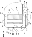
- At least one filter module holder is arranged on an outer wall of the filter system, in particular an outer wall of the basic construction of the filter system, and/or is integrated into the outer wall of the filter system, in particular into the outer wall of the basic construction of the filter system.
- At least one filter module can be arranged on the at least one filter module holder by placing it on the outer wall.
- a filter module can be placed flat against the outer wall.
- the filter module receptacle, in particular the outer wall, and the filter module each comprise an inlet opening and an outlet opening.
- An inlet opening of the filter module and an outlet opening of the filter module can preferably be placed by placing the filter module on the outer wall so as to fit a corresponding inlet opening and a corresponding outlet opening of the outer wall.
- Sealing between the outer wall and the filter module is preferably achieved by means of one or two flanges or flange areas.
- a gas stream flows through a housing, in particular a closed housing, of a filter module, preferably without flowing around the filter module itself.
- the outer wall of the filter system in particular the outer wall of the basic construction of the filter system, preferably has one or more recesses in which one or more filter modules can be arranged.
- two indentations arranged opposite one another with respect to the vertical longitudinal center plane of the filter system and formed substantially mirror-symmetrically to one another are provided in the outer walls of the filter system arranged opposite one another with respect to the vertical longitudinal center plane.
- the indentations preferably extend along a conveying direction of a conveying device of the painting system.
- filter modules Preferably, several filter modules can be accommodated in one recess.
- Doors and/or partitions between individual filter modules are preferably not necessary.
- a filter module comprises a housing which comprises an access opening, for example a door.
- the access opening in particular the door, is arranged, for example, in a rear side of the housing of the filter module.
- the rear side is in particular a side of the housing of the filter module that is accessible from an area surrounding the filter system during filter operation of the filter system.
- the rear side is a side facing away from a front side of the filter module, wherein the front side is preferably that side of the housing of the filter module in which an inlet opening and/or an outlet opening of the filter module are arranged.
- the front side is in particular the side of the filter module with which the filter module can be arranged on the filter module holder.
- filter elements are accessible through an access opening, in particular a door, in the housing of the filter module.
- housing parts of the housing of the filter module are removable.
- filter elements for example a post-filter element of a post-filter device, are designed as insertion elements for insertion, in particular from the side, into the filter module.
- main filter device and/or the post-filter device are designed such that a post-filter device, in particular one or more filter elements of the post-filter device, are accessible and/or replaceable through the main filter device when the main filter device is at least partially dismantled.
- the rate of fire spread can preferably be kept low.
- Moving components in particular a guide device of the filter system, are preferably arranged outside of an area through which a gas flow flows during operation of the filter system. This allows the filter system to be robust and to operate reliably.
- filter modules By placing filter modules on the outer walls of the filter system, more filter modules can be used than if a separate filter module holder was provided for each filter module over the same length of the filter system to accommodate the filter module in a separate interior space.
- the filter modules can thereby preferably be moved closer together. This can preferably increase a filter surface and/or a filter service life.
- one or more inlet openings of a filter module holder and/or one or more inlet openings of a filter module are arranged with respect to the direction of gravity below, in particular directly below, one or more outlet openings of the filter module holder and/or one or more outlet openings of the filter module.
- one or more inlet openings of a filter module holder and/or one or more inlet openings of a filter module are arranged with respect to the direction of gravity above, in particular directly above, one or more outlet openings of the filter module holder and/or one or more outlet openings of the filter module.
- one or more inlet openings on the one hand and one or more outlet openings on the other hand are arranged in the same wall, for example in a front side of a filter module, or in walls that are different from one another.
- a fire is to be understood in particular as a fire causing damage.
- a fire protection element can, for example, be an intermediate wall between two or more filter elements or filter modules of the filter system. Such a fire protection element is in particular a fire protection wall.
- One or more fire protection elements can, for example, be a part or component of one or more filter elements or one or more filter modules.
- a fire protection element is, for example, a section of a filter module, a filter module holder, a filter element and/or a filter element holder.
- a fire protection element is a section of a housing and/or a wall of a filter module, a filter module holder, a filter element and/or a filter element holder.
- the filter system which comprises a fire protection device, preferably has one or more features and/or advantages of the filter systems, which comprise at least one filter module.
- the fire protection device comprises one or more fire protection elements which can be activated in the event of a fire.
- the fire protection device comprises one or more fire protection elements which are movable in the event of a fire, in particular can be introduced into a flow path or fire propagation path or can be removed from the same.
- one or more fire protection elements comprise a fire-retardant material or are formed from a fire-retardant material.
- a fire-retardant material may, for example, comprise a metallic material and/or a ceramic material or be a metallic material and/or a ceramic material.
- a fire-retardant material is in particular a material which, in accordance with the DIN 4102 standard, enables functional integrity in the event of fire for at least approximately 30 minutes (fire resistance class F30, W30, T30), in particular at least approximately 60 minutes (fire resistance class F60, W60, T60), for example at least approximately 90 minutes (fire resistance class F90, W90, T90).
- one or more fire protection elements comprise a material or are formed from a material which can be dissolved, liquefied and/or combustible by the action of heat and/or by contact with a reactant.
- Such a material preferably has a low melting point, low fire resistance, low chemical resistance and/or low physical resistance, in particular with respect to other components and/or parts of the filter system.
- a material that can be dissolved, liquefied and/or combustible by the action of heat and/or contact with a reactant is, for example, a film, fusible link, cardboard or similar.
- one or more fire protection elements comprise a material or are made of a material which can be removed under the influence of heat, so that in particular a passage (extinguishing opening) can be exposed.
- one or more fire protection elements are designed and/or arranged in such a way that the one or more fire protection elements can be removed and/or destroyed by the action of force, in particular by applying a load and/or pressure.
- a material which can be dissolved, liquefied and/or combustible by the action of heat is preferably a material which ensures functional integrity for less than one minute in the event of fire.
- the one or more fire protection elements are arranged in an initial position on one or more receptacles for one or more fire protection elements.
- the material of the one or more fire protection elements preferably has a lower melting point, a lower fire resistance (fire resistance class) and/or a lower chemical and/or physical resistance compared to a material of the one or more receptacles.
- one or more fire protection elements can be removed by the action of heat and/or by contact with a reactive substance and/or by the action of force, in particular without removing, deforming or otherwise impairing the one or more receptacles for receiving the one or more fire protection elements.
- the one or more receptacles are in particular part of the filter system, for example sections of a housing and/or a wall of a filter module, a filter module receptacle, a filter element and/or a filter element receptacle.
- the one or more receptacles are, for example, formed from a metallic material or comprise a metallic material.
- the one or more receptacles are preferably stabilization devices for the mechanical stabilization of one or more fire protection elements during normal operation (filter operation) of the filter system.
- a receptacle comprises a grid or is formed by a grid to which one or more fire protection elements can be placed or are in contact.
- Normal operation of the filter system is in particular a filter operation of the filter system in which impurities are separated from a raw gas stream containing impurities by means of the filter system. In normal operation of the filter system, it can be operated without any impairment.
- the one or more receptacles for the one or more fire protection elements are preferably made of a material which offers a fire resistance class of at least F30, W30, T30, preferably at least F60, W60, T60, for example at least F90, W90, T90.
- one or more extinguishing openings of the filter system can be opened in the event of a fire by means of one or more fire protection elements.
- one or more extinguishing openings of one or more filter elements, one or more filter element receptacles, one or more filter modules and/or one or more filter module receptacles can be opened.
- the one or more extinguishing openings of the filter system are, for example, recesses or gaps in one or more walls of the filter system.
- the recesses or gaps are preferably closed by means of one or more fire protection elements.
- one or more receptacles for the one or more fire protection elements comprise or form one or more extinguishing openings which are closed by one or more fire protection elements during normal operation of the filter system.
- the filter system preferably comprises one or more filter elements and/or one or more filter modules, the interior of which is accessible from the outside in the event of a fire by removing one or more fire protection elements.
- the one or more fire protection elements are activated by the action of heat and/or by contact with a Reactant and/or are removable by the application of force, so that the interior of the one or more filter elements and/or the interior of the one or more filter modules is accessible from the outside.
- the fire protection device comprises an application device by means of which an extinguishing material and/or a reactive substance can be released.
- an extinguishing material can be delivered to burning or fire-prone elements and/or areas of the filter system by means of the application device.
- an extinguishing material and/or a reactive substance can be delivered to one or more fire protection elements by means of the application device.
- the application device is, for example, a sprinkler device.
- a liquid, foam-like or powdery extinguishing material can be dispensed by means of the application device.
- a liquid, foam-like or powdery reaction substance can be dispensed by means of the application device.
- the application device is designed and/or arranged in such a way that when extinguishing material and/or the reaction substance flows out, the extinguishing material and/or the reaction substance flows out in the direction of the one or more fire protection elements and strikes the one or more fire protection elements.
- extinguishing material and/or reaction substance can be released by means of the application device through one or more extinguishing openings of the filter system into an interior of the filter system, in particular after one or more fire protection elements have been removed to release one or more extinguishing openings.
- the extinguishing material and/or the reactive substance can preferably be released into an interior of one or more filter elements and/or into an interior of one or more filter modules.
- the application device is arranged outside an interior space of the filter system, in particular outside a raw gas space of the filter system and/or outside a clean gas space of the filter system.
- the application device can thereby preferably be kept free of contamination contained in the raw gas flow.
- the application device can, for example, be arranged directly above, laterally offset above or laterally next to one or more filter elements and/or one or more filter modules of the filter system.
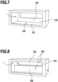
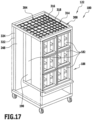
- the filter system comprises one or more filter modules which are designed as movable or shiftable transport trolleys.
- a wall of the one or more transport vehicles preferably comprises one or more extinguishing openings, which are closed by one or more fire protection elements during normal operation of the filter system.
- the one or more extinguishing openings are arranged, for example, on a top side or rear side (back side, rear wall) of the transport trolley.
- the filter system comprises at least one filter module holder, which is arranged on an outer wall of a basic structure of the filter system and/or is integrated into the outer wall of the basic structure.
- At least one filter module can be arranged or is arranged on the at least one filter module holder, preferably by placing it on the outer wall.
- One or more extinguishing openings are then arranged, for example, on or in the outer wall of the basic structure.
- one or more extinguishing openings are arranged on or in a rear side (rear wall) of the at least one filter module facing away from the outer wall.
- the filter system comprises one or more filter modules which are designed as movable or shiftable transport carriages.
- a wall of the one or more transport carriages preferably comprises one or more extinguishing openings which are closed by one or more fire protection elements during normal operation of the filter system.
- one or more ceiling walls and/or side walls, in particular one or more rear walls (back sides), of the one or more transport trolleys comprise one or more extinguishing openings which are closed by means of one or more fire protection elements during normal operation of the filter system.
- the filter system described above is particularly suitable for use in a painting system.
- the present invention therefore also relates to a painting system for painting workpieces, in particular vehicle bodies, which in particular comprises one or more filter systems according to the invention.
- the present invention further relates to a method for operating a filter system for separating contaminants from a raw gas stream containing contaminants.
- the invention relates to a method for operating a filter system according to the invention.
- the method according to the invention preferably provides for the following: activating a fire protection device for preventing, containing and/or extinguishing a fire in the filter system, wherein the spread of flames is influenced by means of one or more fire protection elements of the fire protection device.
- the method according to the invention further preferably has one or more features and/or advantages which, in connection with the inventive Filter systems and/or the painting systems according to the invention and/or the method for separating contaminants.
- one or more fire protection elements are used to open one or more extinguishing openings in the filter system in the event of a fire.
- one or more fire protection elements are preferably initially arranged in such a way that one or more extinguishing openings of the filter system are covered or closed. To release the one or more extinguishing openings, the one or more fire protection elements are preferably removed.
- a fire propagation speed (flame propagation speed) can preferably be reduced and/or a fire spreading from burning filter elements and/or filter modules to other filter elements and/or filter modules can be prevented or at least slowed down.
- a material that can be dissolved, liquefied and/or burned by the action of heat and/or by contact with a reactant is, for example, a fusible material.
- one or more filter modules comprise a frame made of profile components, in particular aluminum profiles.
- Surface components of a filter module are preferably metal plates, for example aluminum plates or aluminum composite plates.
- a filter module has a frame made of aluminium profiles and aluminium plates or aluminium composite panels. walls. In this way, a filter module can be constructed quickly and easily.
- a filter module can in particular be placed, pressed and/or connected to an outer wall of the filter system.
- a seal between a filter module and a filter module holder can be achieved, for example, by means of a sealing profile, in particular a rubber sealing profile.
- a sealing profile or other seal can be arranged, for example, on the filter module and/or the filter module holder.
- a seal between a filter module and a filter module holder is achieved by pressing a sealing element or another seal, for example a sealing profile, onto a flat surface.
- one or more sealing elements are provided on both the filter module and the filter module holder, for example edge protection sealing profiles or rubber clamping profiles.
- the filter system comprises a locking device for locking one or more filter modules to one or more filter module holders.
- the locking device can, for example, comprise one or more locking elements, in particular one or more locking bars.
- the locking element can preferably be brought into engagement with a projection and/or a recess which is arranged, for example, in a base.
- the locking device preferably comprises one or more inclined surfaces so that a clamping effect can be generated when the locking element is brought into engagement with a projection and/or a recess.
- a filter module can be pressed against a filter module holder by means of the locking element of the locking device and/or locked in this position by means of one or more inclined surfaces.
- the locking device can, for example, have one locking element, two locking elements or more than two locking elements per filter module.
- a locking device which serves in particular as a locking device, is preferably used when one or more filter elements can be placed or arranged on an outer wall of the filter system.
- the locking device can also be designed as a door stop, for example a door stop that can be sunk into the floor. This also allows a filter module to be easily and reliably secured to the filter module holder.
- the filter module can preferably be locked and/or fixed in a predetermined position and preferably also pressed against the filter module holder to generate a contact pressure on a seal.
- the filter system in particular a filter module and/or a filter module holder, comprises an actuating device for actuating one or more valve devices.
- Such an actuating device comprises in particular an actuating lever which is coupled to one or more flap elements of the valve device.
- the one or more flap elements of the valve device can preferably be brought from an open position to a closed position or from a closed position to an open position.
- the actuating device comprises a return device, for example a spring, by means of which the actuating lever and/or the one or more flap elements of the valve device are automatically brought into a closed position if the actuating lever is not actuated.
- a return device for example a spring
- the actuating device further comprises a stop and/or a sliding guide, which is arranged, for example, on a filter module and serves to actuate the actuating lever.
- the operating lever and the entire valve device are then preferably arranged on a filter module holder.
- valve device and the actuating lever of the actuating device are arranged on a filter module.
- the stop and/or the slotted guide for actuating the actuating lever is then preferably arranged on the filter module holder.
- the valve device is in particular a flap for closing a clean gas channel from the environment of the filter system.
- a valve device is preferably arranged directly downstream of the filter module.
- the valve device can preferably be actuated mechanically by moving the filter module towards the filter module holder, in particular in such a way that flap elements of the valve device are opened.
- the flap elements of the valve device are preferably closed automatically.
- the opening process and/or the closing process can preferably be triggered by means of the stop and/or a guide slot.
- a volume flow of the gas flowing through a filter module is preferably continuously measured and/or regulated.
- the Volume flow can be determined from the measurement of the differential pressure and/or by means of a pitot tube, a vane wheel and/or a hot wire.
- a speed and/or the power of a fan and/or blower is controlled and/or regulated to adjust a volume flow.
- the fan speed is continuously increased as the filter elements become increasingly full of contaminants and the associated differential pressure increases.
- a changeover time for changing one or more filter elements of a filter module can preferably be determined. For example, it can be provided that one or more filter elements and/or filter modules are replaced when a defined speed limit is reached. In particular, individual filter modules and/or filter elements of a filter module of one or more painting zones of the painting system can be replaced.
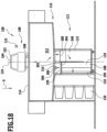
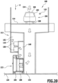
- the filter system includes one or more filter modules and a collecting channel.
- a clean gas stream obtainable by cleaning the raw gas stream can preferably be fed to the collecting channel from the one or more filter modules.
- the collecting channel is arranged above one or more filter modules.
- the collecting channel is arranged directly above the one or more filter modules.
- the collecting channel and the one or more filter modules are thus preferably arranged one after the other in the vertical direction.
- the filter system preferably has a one-sided filter module arrangement in which all filter modules are arranged on a single side of a central raw gas shaft.
- the one or more filter modules are preferably movable on a floor on which the entire filter system is arranged.
- This floor is in particular a hall floor, which is preferably designed for very high loads.
- An inlet opening of a filter module can, for example, be below an outlet opening so that a clean gas stream cleaned by the filter module can leave the filter module upwards.
- a collecting channel is preferably arranged above the outflow openings of the filter modules and serves in particular to discharge clean gas from all filter modules.
- the filter modules on the one hand and the collection channel on the other hand are arranged on opposite sides of the central raw gas shaft.
- the filter system then preferably comprises one or more clean gas channels, by means of which clean gas can be discharged from the filter modules and fed to the collecting channel.
- the one or more clean gas channels preferably cross the raw gas shaft and are surrounded by raw gas, particularly when the filter system is in operation.
- the clean gas channels are arranged in particular above the inlet openings of the filter modules.
- the clean gas channel is preferably arranged at least approximately at the same height as the filter modules with respect to the vertical direction.
- Clean gas ducts crossing the raw gas shaft can also be called branch lines.
- All information regarding a side and/or the central arrangement of the raw gas shaft refers to a cross-section of the filter system and/or the painting system taken perpendicular to a conveying direction of a conveying device.
- the filter system comprises one or more filter modules which include a pre-separation device.
- the pre-separation device preferably comprises one or more separation elements which, for example, have an I-shaped and/or double-T-shaped cross-section.
- one or more separation elements of the pre-separation device are arranged offset from one another and/or nested within one another.
- the pre-separation device is preferably used for the single or multiple flow diversion of a raw gas flow into a filter module. In this way, large and thus inert contaminants in particular can collide with the separation elements of the pre-separation device and thus be separated from the raw gas flow.
- the pre-separation device can, for example, be hung, clipped, snapped in, connected and/or otherwise fastened in front of a main filter device of a filter module.
- the pre-separation device can be arranged, for example, on or in a collecting element, for example a collecting tray.
- the pre-separation device preferably has a flow cross-section which corresponds at least to an inflow cross-section of a filter module.
- the pre-separation device can, for example, comprise one or more segments.
- the pre-separation device extends over individual, several or all filter elements of the main filter device of the filter module.
- the pre-separation device is preferably dismantled.
- the pre-separation device can, for example, comprise cardboard material, plastic material, ceramic material and/or metal or be formed from cardboard material, plastic material, ceramic material and/or metal.
- the pre-separation device can preferably be arranged on a filter module as required, in particular on filter modules which are arranged below painting zones with a high amount of paint overspray.
- the operating time of a filter module until one or more filter elements are replaced can preferably be extended by using a pre-separation device.
- the pre-separation device can preferably be retrofitted to a filter module.
- one or more filter modules comprise one or more filter elements which are slidably accommodated in the filter module.
- the filter module can be tilted as a whole so that one or more filter elements slide out of the filter module.
- these filter elements can be fed directly into a disposal container in this way.
- a filter module is equipped with pre-assembled filter units, which in particular consist of several filter elements. This can preferably accelerate and/or automate the assembly of a filter module.
- a filter module is a driverless transport vehicle or comprises a driverless transport vehicle.
- Such a filter module can preferably move independently to a filter position on a filter module holder and/or to a changing location for changing one or more filter elements.
- the filter system comprises a separate vehicle with a drive, in particular a driverless transport vehicle, by means of which a, preferably driveless, filter module can be transported from a filter module holder to a changing location and/or from the changing location to the filter module holder.
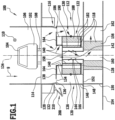
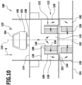
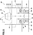
- the first embodiment of a painting system designated as a whole by 100, shown is used for painting workpieces 102, for example vehicle bodies 104.
- the painting system 100 is in particular a spray painting system or aerosol painting system in which a liquid or powdered paint is accelerated in the direction of the workpiece 102 in order to coat the workpiece 102.
- a painting booth 106 in which the actual painting process takes place, is passed through with an air stream in the direction of gravity g from top to bottom.
- this air stream picks up paint particles and/or paint droplets that do not adhere to the workpiece 102 and is thus contaminated.
- the gas stream obtained in this way is referred to as the raw gas stream, which contains paint overspray particles or paint overspray droplets as impurities.
- the painting system 100 comprises a conveying device 108, by means of which the workpieces 102, in particular the vehicle bodies 104, can be conveyed through the painting booth 106 in a conveying direction 110.
- the painting system 100 comprises a filter system 112, which is arranged directly below the painting booth 106 and to which the raw gas stream can be fed through a booth floor 114 of the painting booth 106.
- the filter system 112 comprises a basic structure 116, in particular a frame or a housing, in which several filter devices 118 are arranged.
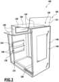
- the basic construction 116 of the filter system 112 has a plurality of filter module receptacles 120 for receiving a plurality of filter modules 122.
- the filter module holders 120 are arranged in a fixed position on the painting system 100, in particular on the filter system 112.
- the filter modules 122 are preferably designed to be movable and can be optionally inserted into the filter module receptacles 120 or removed from them.
- two filter module receptacles 120 and two filter modules 122 are arranged opposite one another with respect to a vertical longitudinal center plane 124 of the painting booth 100, in particular of the filter system 112, and in particular are designed essentially mirror-symmetrically to one another.
- the filter system 112 preferably comprises further filter module receptacles 120 and filter modules 122, which preferably form two rows of filter module receptacles 120 and filter modules 122 arranged one behind the other, extending along the conveying direction 110.
- Each filter module receptacle 120 preferably comprises an interior space 126 which can be made accessible or closed by means of valve devices 128 associated with the respective filter module receptacle 120.
- a separate flow channel 130 of the filter system 112 is formed by means of each filter module holder 120.
- a part of the raw gas flow can be passed through each flow channel 130 essentially independently of the other flow channels 130.
- a portion of the raw gas flow can be specifically freed of impurities in each flow channel 130 so that it can be discharged as a clean gas flow from the respective filter module holder 120.
- Each filter module receptacle 120 comprises a valve device 128, for example designed as a flap 132, which is arranged, for example, at an inlet opening 134 of the filter module receptacle 120.
- the inlet opening 134 provided with the flap 132 is in particular a bypass opening 136 of the filter module holder 120.
- each filter module receptacle 120 preferably comprises a further inlet opening 134, against which a pre-filter device (to be described later) of the associated filter module 122 rests during filter operation of the filter system 112.
- the further inlet opening 134 is arranged in a side wall 140 of the filter module holder 120, which is arranged facing the vertical longitudinal center plane 124 of the filter system 112.
- a raw gas shaft 142 is formed by means of the side walls 140 of the filter module receptacles 120, through which the raw gas discharged from the painting booth 106 and contaminated with paint overspray can be fed to the filter devices 118.
- the filter module receptacles 120 further each comprise at least one outlet opening 144 through which the gas flow passed through the filter module receptacle 120 can be discharged.
- each filter module holder 120 is assigned an access opening 146, in particular a lockable door 148.
- the filter module receptacles 120 and correspondingly also the filter modules 122 in the first embodiment shown are arranged on a level 152 which is arranged above a floor 154 on which in turn the entire painting system 100 is constructed.
- additional filter devices 156 are arranged, which are preferably different filter devices 118 from the filter devices 118 of the filter modules 122.
- the side walls 140 of the filter module receptacles 120 comprise the outlet openings 144.
- the outlet openings 144 are arranged below the inlet openings 134 with respect to the direction of gravity g and are separated from one another by means of a partition wall 158 which connects the filter module receptacles 120 arranged opposite one another with respect to the vertical longitudinal center plane 124 along a substantially horizontal plane.
- the area above the partition wall 158 is the raw gas shaft 142.
- the area under the partition wall 158 is the area into which the gas stream purified by means of the filter device 118 flows and which is therefore referred to as the clean gas channel 160.
- the clean gas flowing out of the filter module receptacles 120 which is obtainable by cleaning the contaminated raw gas, can be fed to the additional filter devices 156 through the clean gas channel 160.
- the additional filter devices 156 are then flowed through in a substantially horizontal direction in order to further increase the purity of the clean gas.
- this clean gas is fed to two collecting channels 162 which are arranged on the sides of the additional filter devices 156 facing away from the vertical longitudinal center plane 124.
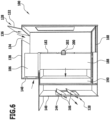
- each filter module holder 120 is in the Fig. 1 to 8 illustrated first embodiment of the painting system 100, in particular the filter system 112, is aligned substantially horizontally.
- the ceiling wall 138 forms a flow guide plate 164, by means of which the raw gas flow can be fed specifically to the inlet openings 134.
- the filter module holder 120 also comprises a plurality of sealing areas 170 for creating corresponding sealing areas 170 of a filter module 122.
- the guide device 168 serves in particular for moving, guiding and/or locking a filter module 122 relative to the filter module holder 120.
- the guide device 168 comprises in particular a telescopic rail guide 172, by means of which a filter module 122 from the Fig.1 shown filter position can be brought into a change position.
- the sealing areas 170 of the filter module holder 120 and the sealing areas 170 of the filter module 122 abut one another, so that a gas flow flowing through the filter module holder 120 and the filter module 122 reliably follows a predetermined flow path.
- a first sealing region 170 of the filter module holder 120 is designed as an inlet region 174 of the inlet opening 134 arranged in the side wall 140.
- the inlet region 174 is in particular a projection protruding into the interior 126 of the filter module holder 120.
- the guide device 168 is designed as a telescopic rail guide 172 as described above.
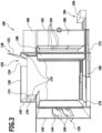
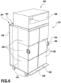
- a roller device 178 can also be provided (see Fig. 4 to 6 ).
- the filter module 122 is preferably designed as a transport carriage 180.
- this transport carriage 180 By means of this transport carriage 180, in particular several filter elements 182 can be transported together.
- the filter module 122 comprises a plurality of filter element receptacles 184 for receiving a plurality of filter elements 182.
- the filter elements 182 and the filter element receptacles 184 are preferably arranged and/or designed independently of one another such that individual filter elements 182 can be removed from the filter element receptacles 184 independently of the other filter elements 182 and can be replaced, for example to replace contaminated filter elements 182 with fresh filter elements 182.
- the filter module 122 preferably comprises three filter devices 118, through which the gas stream flows one after the other with respect to a flow direction during filter operation of the filter system 112.
- a pre-filter device 186 a main filter device 188 and a post-filter device 190 are provided.
- the pre-filter device 186 is, for example, an inertial filter with a single or multiple flow deflection.
- the pre-filter device 186 preferably comprises only a single filter element 182.
- a filter element holder 184 for receiving the filter element 182 of the pre-filter device 186 can, for example, be a frame 192 or rack 194 of the filter module 122.
- the pre-filter device 186 is in particular arranged directly above the main filter device 188.
- the main filter device 188 comprises several, for example six, filter element receptacles 184 for receiving several, in particular six, filter elements 182.
- the filter elements 182 of the main filter device 188 are preferably inertial separators, for example disposable filters.
- the post-filter device 190 is arranged laterally adjacent to the main filter device 188.
- the post-filter device 190 comprises in particular a single filter element 182, which is designed, for example, as a mat filter.
- the filter elements 182 of the pre-filter device 186, the main filter device 188 and the post-filter device 190 can be flowed through in a substantially horizontal direction.
- a flow direction of the pre-filter device 186 is opposite to the flow direction of the main filter device 188 and the post-filter device 190.
- the filter module 122 further comprises at least one collecting element 196, by means of which falling contaminants can be collected during filter operation of the filter module 122 and/or when replacing filter elements 182.
- the collecting element 196 is designed in particular as a trough 198.
- the filter module 122 also comprises one or more handling elements 200, for example handles 202, by means of which a person can easily grasp the filter module 122 in order to move it.
- handling elements 200 for example handles 202, by means of which a person can easily grasp the filter module 122 in order to move it.
- the filter module 122 can be moved by means of a separate transport device 204 in addition to the possibility of movement by means of the guide device 168.
- the transport device 204 can, for example, be a lifting truck device 206, by means of which the filter module 122 can be lifted and transported away.
- one or more filter modules 122 can be moved, in particular transported, by means of an overhead conveyor or a driverless transport system.
- the filter module 122 is in particular guided from a filter position (see Fig.6 ) into a change position and/or from the change position into the filter position.
- the filter module 122 can be picked up and transported away from the position in which it is in the change position. Furthermore, a filter module 122 can be transported to the filter system 112 by means of the transport device 204. transportable, in particular such that a transported filter module 122 can be brought into the change position.
- the filter system 112 can comprise a changing device 208 for automatically changing individual or multiple filter elements 182 or individual or multiple filter modules 122.
- the changing device 208 is designed in particular as a robot device 210 and is movable in and against the conveying direction 110 along the filter system 112.
- Such a changing device 208 can be provided on one side or on both sides of the filter system 112 (in Fig.1 only shown on one side).
- the painting system 100 described above functions as follows: During operation of the painting system 100, the air passed through the painting booth 106 is contaminated with paint overspray and fed to the filter system 112 as a contaminated raw gas stream.
- the raw gas stream flows partially into the raw gas shaft 142 and through the inlet openings 134 in the side walls 140 into the filter module receptacles 120.
- a further part of the raw gas flow in particular a part of the raw gas flow flowing near the outer walls 150 of the painting booth 106 and the filter system 112, preferably flows through the bypass openings 136, that is to say through the inlet openings 134 in the ceiling walls 138, of the filter module receptacles 120 into the interior 126 of the filter module receptacles 120.
- the pre-filter devices 186 of the filter modules 122 are directly adjacent to the inlet openings 134 in the side walls 140 of the filter module receptacles 120, the part of the raw gas flow flowing in through these inlet openings 134 in the side walls 140 is passed through the pre-filter devices 186 and is thus already freed from some of the contaminants contained therein.
- this part of the raw gas flow is combined with the raw gas flow passed through the bypass openings 136 and fed to the main filter devices 188.
- the raw gas stream is further cleaned and then fed to the secondary filter devices 190 for even more thorough removal of contaminants.
- the gas stream thus purified leaves the filter module receptacles 120 as a clean gas stream through the outlet openings 144 of the filter module receptacles 120.
- the clean gas flow then enters the clean gas channel 160.
- the clean gas flow is guided downwards in the direction of gravity g and then fed in a horizontal direction to the additional filter devices 156.
- the clean gas stream After an additional cleaning of the clean gas stream by means of the additional filter devices 156, the clean gas stream enters the collecting channels 162 and is discharged from the filter system 112 by means of the collecting channels 162.
- the filter elements 182 of the filter devices 118 are loaded with contaminants, in particular contaminated with paint overspray.
- the filter performance of the filter elements 182 is thereby reduced. Furthermore, the flow resistance of the filter elements 182 is increased.
- the filter system 112 then no longer operates with maximum efficiency.
- the filter elements 182 must be replaced at regular intervals, with more heavily contaminated filter elements 182 being replaced in particular by fresh filter elements 182.
- the inlet opening 134 in the top wall 138 and/or the outlet opening 144 in the side wall 140 are first closed by means of the valve devices 128.
- the flow through the filter module holder 120 is thus interrupted.
- the access opening 146 in particular the door 148, can be opened in order to move the filter module 122 from the filter position to the change position.
- the inlet opening 134 in the ceiling wall 138 is closed, then the access opening 146, in particular the door 148, is opened and then the outlet opening 144 in the side wall 140 is closed.
- outlet opening 144 may also remain open continuously, in particular during the entire changing process.
- the filter module 122 can be moved back into the filter position and is then available for further filter operation after the valve devices 128 are opened.
- the entire filter module 122 is removed from the filter system 112 and replaced by a fresh filter module 122, that is, a filter module 122 with fresh filter elements 182.
- filter module receptacles 120 form essentially independent flow channels 130 of the filter system 112
- individual filter modules 122 or Filter elements 182 can also be replaced during operation of the filter system 112, since when individual filter modules 122 are replaced, i.e. temporarily switched off, the remaining filter modules 122 continue to ensure the cleaning function of the filter system 112.
- pre-filter devices 186 are shown, which, depending on requirements, can be used as pre-filter device 186 of the described filter modules 122.
- a pre-filter device 186 is shown, in which a one-time flow diversion is provided.
- a bottom wall 212 and a lower section 214 of a rear wall 216 of the filter element 182 of the pre-filter device 186 form an impact area 218, on which contaminants, in particular paint overspray particles, accumulate during the flow diversion.
- the Fig.8 The embodiment of the pre-filter device 186 shown differs therefrom essentially in that the filter element 182 comprises an intermediate wall 220.
- the Fig.8 In the embodiment of the pre-filter device 186 shown, a double flow diversion is provided.
- the bottom wall 212, the intermediate wall 220 and an upper section 222 of the rear wall 216 serve as impact areas 218 for the separation of contaminants, in particular paint overspray particles.
- FIG.9 The second embodiment of a painting system 100, in particular a filter system 112, shown in the Fig. 1 to 8 illustrated embodiment essentially in that the ceiling wall 138 of each filter module holder 120, which serves as a flow guide plate 164, is inclined instead of being essentially horizontal.
- the flow guide plates 164 of the filter system 112 thereby enable a different flow guidance, in particular a different distribution of the raw gas flow to the Bypass opening 136 and the inlet opening 134 in the side wall 140 of each filter module holder 120.
- FIG.9 The second embodiment of the painting system 100, in particular the filter system 112, shown corresponds in terms of structure and function to the first embodiment described above, so that reference is made to its above description in this respect.
- FIG.10 The third embodiment of a painting system 100, in particular a filter system 112, shown in the Fig. 1 to 8 illustrated first embodiment essentially in that the raw gas shaft 142 extends over the entire height of the filter module receptacle 120 and only a single inlet opening 134, namely an inlet opening 134 in the side wall 140 of each filter module receptacle 120, is provided.
- each filter module holder 120 thus has a closed surface.
- the inlet opening 134 in the side wall 140 is immediately followed by the main filter device 188, which is followed in the flow direction by the secondary filter device 190.
- no pre-filter device 186 is provided.
- each filter module receptacle 120 is arranged in a plane 152 that delimits the filter module receptacle 120 at the bottom.
- the outlet opening 144 is arranged on the side of the filter module 122 facing away from the vertical longitudinal center plane 124.
- the clean gas flow reaches the side of an additional filter device 156 facing away from the vertical longitudinal center plane 124.
- the additional filter device 156 is thus flowed through in a direction directed towards the vertical longitudinal center plane 124.
- a collecting channel 162 is arranged, through which the clean gas discharged from all filter modules 122 is discharged centrally.
- the third embodiment of the painting system 100, in particular of the filter system 112, shown can offer the advantage that the filter modules 122 are accessible through the access openings 146 from a clean gas side of the filter system 112.
- the risk of unwanted escape of contaminated raw gas when opening the access opening 146, in particular the door 148, to change the filter modules 122 is preferably reduced thereby.
- Fig.10 illustrated third embodiment of the painting system 100, in particular the filter system 112, in terms of structure and function with the
- Fig. 1 to 8 illustrated first embodiment, so that reference is made to the above description thereof in this respect.
- FIG. 11 and 12 The fourth embodiment of a painting system 100, in particular a filter system 112, shown in the Fig. 1 to 8 illustrated first embodiment essentially in that the raw gas shaft 142 extends along the vertical longitudinal center plane 124 to a bottom 154 of the filter system 112.
- the filter module holders 120 are also arranged on the floor 154 of the filter system 112 and are installed according to the Fig.10 In the third embodiment shown, raw gas flows from the inside to the outside.
- the clean gas obtained after flowing through the filter modules 122 is discharged via outlet openings 144 of the filter module receptacles 120 arranged in the ceiling wall 138.
- Additional filter devices 156 and collection channels 162 are arranged above the filter module receptacles 120 in order to further clean the clean gas and finally discharge it from the filter system 112.
- the painting system 100 comprises the Fig. 11 and 12 illustrated fourth embodiment preferably a fire protection device 224.
- the fire protection device 224 can in particular comprise flap elements 226 or sliding elements 228, which can be introduced into the raw gas shaft 142 in the event of a fire in order to close it.
- the flap elements 226 or sliding elements 228 can in particular be extensions of walls of the filter module receptacles 120, which can be introduced into the raw gas shaft 142 if required, in particular can be folded in or pushed in.
- the flap elements 226 or the sliding elements 228 are preferably assigned to individual filter module receptacles 120 and can thus preferably also be introduced into the raw gas shaft 142 in the area of individual filter module receptacles 120 independently of the flap elements 226 or sliding elements 228 of the other filter module receptacles 120. This allows this area to be protected from unwanted contamination when the filter is changed and the associated filter module 122 can be replaced conveniently and with as little contamination as possible.
- all walls of the filter module holder 120 and/or the filter system 112 are preferably fire protection walls.
- Fig. 11 and 12 illustrated fourth embodiment of a painting system 100, in particular a filter system 112, in terms of structure and function with the one shown in the Fig. 1 to 8 illustrated first embodiment, so that reference is made to the above description thereof in this respect.
- FIG. 13 and 14 The fifth embodiment of a painting system 100, in particular a filter system 112, shown in the Fig. 1 to 8 illustrated first embodiment essentially in that the filter module receptacles 120 are designed as contact areas 230 on the outer walls 150 of the filter system 112, in particular the basic structure 116 of the filter system 112.
- the outer walls 150 are provided with recesses 232 in which the filter modules 122 can be arranged.
- the recesses 232 are open. When the filter system 112 is in operation, the filter modules 122 are thus accessible from outside the filter system 112.
- the side wall 140 of the filter module holder 120 which is also the outer wall 150 of the base structure 116, comprises in the Fig. 13 and 14 illustrated embodiment of the filter system 112 has an inlet opening 134 and an outlet opening 144.
- the inlet opening 134 and the outlet opening 144 are arranged one above the other with respect to the direction of gravity g and separated from each other by a partition wall 158.
- the inlet opening 134 is arranged above the outlet opening 144.
- the filter modules 122 that can be attached to the system areas 230 each comprise a main filter device 188 and a post-filter device 190.
- a pre-filter device 186 can also be provided.
- the filter modules 122 each comprise a housing 234, which is or can be closed in a fluid-tight manner, in particular on five sides.
- the filter module holder 120 and/or the filter module 122 comprises two flange areas which surround the inlet opening 134 and the outlet opening 144 and seal the filter module holder 120 and the associated filter module 122 from an environment of the filter system 112.
- Each filter module 122 comprises an inflow section 238, which adjoins the inlet opening 134, a reversing section 240 for reversing the flow, a return section 242 for returning the gas flow towards the front side 236 of the filter module 122 and an outflow section 244, through which the gas flow can be fed to the outlet opening 144.
- the inflow section 238 is arranged above the outflow section 244 according to the arrangement of the inlet opening 134 and the outlet opening 144.
- the return section 242 is arranged in particular under the main filter device 188 and the post-filter device 190.
- the reversing section 240 is arranged in particular in the region of a rear side 246 of the filter module 122 arranged opposite the front side 236 of the filter module 122.
- the rear side 246 of the filter module 122 comprises in particular an access opening 146, for example a door 148, through which an interior space 248 of the filter module 122 is accessible. This allows the filter elements 182 of the post-filter device 190 and/or the main filter device 188 to be accessible for easy replacement thereof.
- Fig. 14 can be seen from the Fig. 13 and 14
- the guide device 168 is arranged outside an area of the filter system 112 through which a gas flow flows. Undesirable contamination of the guide device 168 during filter operation of the filter system 112 can thereby be reduced or completely avoided.
- the fifth embodiment of the painting system 100 in particular the filter system 112, shown in FIG. 1, is similar in terms of structure and function to the Fig. 1 to 8 illustrated first embodiment, so that reference is made to the above description thereof in this respect.
- the sixth embodiment of a painting system 100 shown differs from that shown in the Fig. 13 and 14 illustrated fifth embodiment essentially in that the painting system 100, in particular the filter system 112, comprises a fire protection device 300.
- a fire in the filter system 112 can in particular be prevented, contained and/or extinguished.
- the fire protection device 300 comprises one or more fire protection elements 302 for influencing the spread of flames in the event of a fire.
- the fire protection elements 302 can slow down the spread of fire, in particular if the fire protection elements 302 are made of a fire-retardant material with a high fire resistance class.
- the fire protection elements 302 are formed from a material which can be dissolved, liquefied and/or combustible by the action of heat and/or by contact with a reactant.
- the material of the fire protection elements 302 is in particular selected such that in the event of a fire the fire protection elements 302 can be removed or otherwise eliminated in order to create an access opening or passage opening.
- the access opening or passage opening then forms in particular a discharge opening 304 through which an interior space 248 of the filter modules 122 is accessible (see Fig. 17 ).
- the fire protection device 300 further comprises an application device 306, by means of which an extinguishing material and/or a reactive substance can be dispensed.
- the application device 306 is in the Fig. 15 to 17
- the filter modules 122 are arranged directly above the filter modules 122, so that the extinguishing material and/or the reaction substance can be discharged from above onto a ceiling wall 308 of the filter modules 122.
- the application device 306 is designed in particular as a sprinkler device 310, by means of which liquid, foam-like or powdery extinguishing material and/or liquid, foam-like or powdery reactive substance can be dispensed.
- the application device 306 is arranged outside a raw gas chamber 312 of the filter system 112 and outside the filter modules 122. Undesirable contamination of the application device 306 during normal operation (filter operation) of the filter system 112 can be prevented in this way.
- each filter module 122 comprises a receptacle 314 for receiving one or more fire protection elements 302.
- the receptacle 314 comprises in particular a stabilization device 316 for the reliable and stable reception and/or arrangement of the one or more fire protection elements 302.
- the stabilization device 316 is designed, for example, as a grid 318, onto which the one or more fire protection elements 302 can be placed.
- the Fig. 15 to 17 The sixth embodiment of a painting system 100 shown, in particular the fire protection device 300, functions as follows: In the event of a fire in the filter system 112, a fire may spread within the filter system 112.
- the spread of the fire in particular the fire propagation speed (fire propagation speed) can be influenced in a targeted manner.
- the spread of fire from individual filter modules 122 to neighboring filter modules 122 can be prevented or at least slowed down by means of fire protection elements 302 designed as fire-retardant partition walls.
- fire protection elements 302 are formed from a material that can be dissolved, liquefied and/or combustible by exposure to heat (heat exposure) and/or by contact with a reactant.
- one or more extinguishing openings 304 in a ceiling wall 308 of the filter modules 122 can be exposed.
- the fire protection elements 302 are formed, for example, from a meltable or combustible material.
- the fire protection elements 302 are formed from cardboard and thus burn in the event of a fire in order to release the extinguishing openings 304.
- a reactant can be delivered to the one or more fire protection elements 302 by means of the application device 306 in order to dissolve or otherwise remove the one or more fire protection elements 302. This can also open up one or more extinguishing openings 304 in the ceiling walls 308 of the filter modules 122.
- an interior space 248 of the filter modules 122 is accessible in particular, so that extinguishing material can be introduced into the filter modules 122 through the extinguishing openings 304 by means of the application device 306.
- FIG. 15 to 17 The sixth embodiment of a painting system 100 shown in FIG. 1 is similar in structure and function to that shown in FIG. Fig. 13 and 14 illustrated fifth embodiment, so that reference is made to the above description thereof in this respect.
- FIG. 18 The seventh embodiment of a painting system 100 shown in FIG. 1 differs from that shown in FIG. Fig. 15 to 17
- the sixth embodiment shown essentially differs in that only a single row of centrally arranged filter modules 122 is provided. Such a design is particularly useful when the amount of overspray in the paint booth 106 is rather low.
- the raw gas flow flows essentially vertically from above through the ceiling wall 308 of the respective filter module 122 into the respective filter module 122.
- the raw gas flow then flows through two filter devices 118, namely a main filter device 188 and a post-filter device 190, which are part of the respective filter module 122.
- the gas stream flowing out of the filter modules 122 is finally passed through an additional filter device 156 and finally discharged as a clean gas stream.
- a fire protection device 300 is also available in Fig. 18 shown seventh embodiment of a painting system 100. This is arranged in particular directly above an intermediate wall 320 of the filter system 112.
- the intermediate wall 320 can be part of the ceiling wall 308, in particular a part of the ceiling wall 308, of each filter module 122. However, it can also be provided that the intermediate wall 320 is part of the basic construction 116 of the filter system 112.
- the intermediate wall 320 separates in particular that area or interior space 248 of the respective filter module 122 in which the filter devices 118 are arranged, from that space of the filter system 112 in which the application device 306 of the fire protection device 300 is arranged. Even in the case of the Fig. 18 In the seventh embodiment of the painting system 100 shown, the application device 306 is thus preferably arranged outside a gas flow, in particular outside the raw gas space 312.
- the fire protection element 302 forming the intermediate wall 320 is removable to provide access to the interior 248 of the filter modules 122.
- each filter module 122 can be released.
- extinguishing material can then be delivered into the interior 248 of the respective filter module 122, in particular in order to contain or extinguish a fire present therein.
- FIG. 18 The seventh embodiment of a painting system 100 shown in FIG. 1 is similar in structure and function to that shown in FIG. Fig. 15 to 17 illustrated sixth embodiment, so that reference is made to its above description in this respect.
- FIG. 19 The eighth embodiment of a painting system 100 shown differs from that shown in Fig. 18 illustrated seventh embodiment essentially in that the application device 306 of the fire protection device 300 is arranged laterally offset above the filter modules 122.
- the application device 306 is arranged and aligned such that an extinguishing material and/or a reactive substance can be delivered to one or more side walls 322 of the filter modules 122.
- extinguishing material and/or a reactant can be delivered to one or more rear walls 324 of one or more filter modules 122.
- the extinguishing openings 304 which are initially covered by fire protection elements 302, and thus also the associated receptacles 314, are arranged accordingly on the side walls 322, in particular on the rear walls 324, of the filter modules 122.
- extinguishing material in particular can be introduced laterally into the interior 248 of the filter modules 122 in order to contain or extinguish a fire.
- FIG. 19 illustrated eighth embodiment of a painting system 100 in terms of structure and function with the in Fig. 18 illustrated seventh embodiment, so that reference is made to its above description in this respect.
- FIG. 20 The ninth embodiment of a painting system 100 shown in FIG. 1 differs from that shown in FIG. Fig. 13 and 14 illustrated fifth embodiment essentially in that the filter modules 122 are arranged so as to be movable on the floor 154 on which the entire painting system 100 is constructed.
- all filter modules 120 are arranged on the same side of the central raw gas shaft 142.
- the filter modules 120 preferably each comprise a main filter device 188 and a post-filter device 190.
- the filtered gas can be fed to one or more additional filter devices 156 via a clean gas channel 160.
- the additional filter devices 156 are arranged in particular in a stationary manner on the base structure 116 and preferably serve as police filters or additional filters to prevent undesirable contamination of the clean gas side of the painting system 100.
- the clean gas flow passed through the additional filter devices 156 can be fed to the collecting channel 162, to which in particular clean gas from all filter modules 122 can be fed.
- the clean gas can finally be discharged from the filter system 112 and, for example, be used for further purposes.
- the collecting channel 162 is at the Fig. 20 illustrated ninth embodiment of the painting system 100, in particular the filter system 112, is arranged above the filter modules 122. In particular, the collecting channel 162 is arranged directly above the filter modules 122.
- the collecting channel 162 and the filter modules 122 are thus arranged one after the other in the vertical direction.
- a distance can be provided between the collecting channel 162 and the filter modules 122, which can be bridged, for example, by means of one or more clean gas channels 160.
- the collecting channel 162 directly adjoins the filter modules 122 in the vertical direction.
- FIG. 20 The ninth embodiment of a painting system 100 shown in FIG. 1 is similar in structure and function to that shown in FIG. Fig. 13 and 14 illustrated fifth embodiment, so that reference is made to the above description thereof in this respect.
- FIG. 21 The tenth embodiment of a painting system 100, in particular a filter system 112, shown in Fig. 20 illustrated ninth embodiment essentially in that the one or more clean gas channels 160 cross the raw gas shaft 142 and thus have raw gas flowing around them during operation of the filter system 112.
- the filter modules 122 on the one hand and the collecting channel 162 on the other hand are arranged on opposite sides of the central raw gas shaft 142.
- the collecting channel 162 is arranged substantially at the same height as the filter modules 122 with respect to the vertical direction (gravity direction g).
- FIG. 21 The tenth embodiment of the painting system 100 shown in FIG. 1 is similar in terms of structure and function to that shown in FIG. Fig. 20 depicted ninth embodiment, so that reference is made to the above description in this respect.
- filter modules 122 and/or filter module receptacles 120 are described with reference to the Fig. 22 to 28 explained. These features can be provided either individually or in combination with one another as an alternative or in addition to one or more of the above-described features of the filter modules 122 or the filter module receptacles 120.
- a locking device 400 is provided, by means of which the filter module 120 can be locked in a desired position, in particular a filter position on the filter module holder 120.
- the locking device 400 comprises in particular a locking element 402, for example designed as a drive bolt rod, which can be actuated by means of a handle 404 of the locking device 400.
- the locking element 402 At its lower end with respect to the direction of gravity g, the locking element 402 comprises an inclined surface 406, which can be brought into engagement with an inclined surface 406 in a projection 408 on the base 154.
- the inclined surfaces 406 are in particular aligned relative to one another in such a way that the filter module 122 is pressed against the filter module holder 120 by means of the handle 404 when the locking element 402 is actuated.
- the inclined surface 406 of the locking element 402 can be brought into engagement with an inclined surface 406 in a recess 410 in the base 154. Due to such a recess 410, a potentially disturbing projection 408 on the base 154 can be avoided. In functional terms, however, the recess 410 essentially corresponds to the projection 408.
- a filter module 122 comprises a pre-separation device 412.
- Such a pre-separation device 412 can be designed in particular as a labyrinth filter 414 or inertia filter 416.
- a single or multiple flow reversal or flow deflection preferably takes place, so that heavy contaminants in particular cannot follow a gas flow passed through the pre-separation device 412 and adhere to separation elements 418 of the pre-separation device 412 and are thus separated from the raw gas flow.
- the separation elements 418 can in particular have a substantially I-shaped or double-T-shaped cross-section.
- separation elements 418 are arranged offset from one another and/or nested within one another, in particular in order to realize the single or multiple flow deflection.
- the pre-separation device 412 can preferably be arranged optionally and/or as required on a filter module 122.
- the pre-separation device 412 as a whole can be arranged in front of a main filter device 188 of a filter module 122.
- the pre-separation device 412 preferably extends over the entire inlet area of the main filter device 188.
- the pre-separation device 412 is preferably arranged above, in particular directly above, a tray 198 of the filter module 122 that serves as a collecting element 196. In this way, liquid dripping down from the pre-separation device 412 can be easily caught and collected.
- an actuating device 420 is provided, by means of which the valve device 128 can be actuated.
- the actuating device 420 can be actuated in particular mechanically by pressing the filter module 122 against the valve device 128.
- the actuating device 420 comprises in particular an actuating lever 422, which can be brought into engagement with a stop 424 of the actuating device 420 (see the Fig. 26 and 28 ).
- the actuating lever 422 is in particular coupled to one or more flap elements 426 of the valve device 128, so that by a movement of the actuating lever 422 the flap elements 426 can be brought from an open position to a closed position or from a closed position to an open position.
- the actuating lever 422 can, for example, be spring-loaded so that the flap elements 426 are automatically moved into the positions defined in the Fig. 25 and 26 brought into the closed position shown.
- the stop 424 of the actuating device 420 is in particular a lateral projection of the filter module 122.
- the actuating device 420 is in particular an actuating device 420 by means of which the valve device 128 is automatically opened when the filter module 122 is arranged in a predetermined position on a filter module holder 120.
- the valve device 128 is preferably automatically closed.
Landscapes
- Chemical & Material Sciences (AREA)
- Chemical Kinetics & Catalysis (AREA)
- Health & Medical Sciences (AREA)
- Engineering & Computer Science (AREA)
- Environmental & Geological Engineering (AREA)
- Toxicology (AREA)
- Filtering Of Dispersed Particles In Gases (AREA)
- Details Or Accessories Of Spraying Plant Or Apparatus (AREA)
Applications Claiming Priority (5)
| Application Number | Priority Date | Filing Date | Title |
|---|---|---|---|
| DE102013222301.3A DE102013222301B4 (de) | 2013-11-04 | 2013-11-04 | Filteranlage zum Abscheiden von Verunreinigungen aus einem Verunreinigungen enthaltenden Rohgasstrom, Lackieranlage und Verfahren zum Abscheiden von Verunreinigungen aus einem Verunreinigungen enthaltenden Rohgasstrom |
| DE202014103177.4U DE202014103177U1 (de) | 2013-11-04 | 2014-07-10 | Filteranlage und Lackieranlage |
| EP14789261.6A EP3065845B1 (fr) | 2013-11-04 | 2014-10-23 | Installation de filtration et dispositif pour faire fonctionner une installation de filtration |
| PCT/EP2014/072797 WO2015062976A2 (fr) | 2013-11-04 | 2014-10-23 | Installation de filtrage, installation de vernissage et procédé pour faire fonctionner une installation de filtrage |
| EP19176604.7A EP3556450A1 (fr) | 2013-11-04 | 2014-10-23 | Installation filtrante et installation de peinture |
Related Parent Applications (2)
| Application Number | Title | Priority Date | Filing Date |
|---|---|---|---|
| EP19176604.7A Division EP3556450A1 (fr) | 2013-11-04 | 2014-10-23 | Installation filtrante et installation de peinture |
| EP14789261.6A Division EP3065845B1 (fr) | 2013-11-04 | 2014-10-23 | Installation de filtration et dispositif pour faire fonctionner une installation de filtration |
Publications (2)
| Publication Number | Publication Date |
|---|---|
| EP4434638A2 true EP4434638A2 (fr) | 2024-09-25 |
| EP4434638A3 EP4434638A3 (fr) | 2024-12-04 |
Family
ID=51419531
Family Applications (3)
| Application Number | Title | Priority Date | Filing Date |
|---|---|---|---|
| EP19176604.7A Pending EP3556450A1 (fr) | 2013-11-04 | 2014-10-23 | Installation filtrante et installation de peinture |
| EP14789261.6A Active EP3065845B1 (fr) | 2013-11-04 | 2014-10-23 | Installation de filtration et dispositif pour faire fonctionner une installation de filtration |
| EP24191309.4A Pending EP4434638A3 (fr) | 2013-11-04 | 2014-10-23 | Installation de filtration, installation de peinture et procédé de fonctionnement d'une installation de filtration |
Family Applications Before (2)
| Application Number | Title | Priority Date | Filing Date |
|---|---|---|---|
| EP19176604.7A Pending EP3556450A1 (fr) | 2013-11-04 | 2014-10-23 | Installation filtrante et installation de peinture |
| EP14789261.6A Active EP3065845B1 (fr) | 2013-11-04 | 2014-10-23 | Installation de filtration et dispositif pour faire fonctionner une installation de filtration |
Country Status (17)
| Country | Link |
|---|---|
| US (5) | US10596504B2 (fr) |
| EP (3) | EP3556450A1 (fr) |
| JP (2) | JP6591972B2 (fr) |
| KR (1) | KR102269478B1 (fr) |
| CN (2) | CN105705216A (fr) |
| BR (1) | BR112016009240B1 (fr) |
| CA (1) | CA2929060C (fr) |
| DE (3) | DE102013222301B4 (fr) |
| ES (1) | ES2745980T3 (fr) |
| HU (1) | HUE046341T2 (fr) |
| MX (1) | MX379037B (fr) |
| MY (1) | MY181407A (fr) |
| PL (1) | PL3065845T3 (fr) |
| PT (1) | PT3065845T (fr) |
| RU (1) | RU2697452C2 (fr) |
| WO (1) | WO2015062976A2 (fr) |
| ZA (1) | ZA201603046B (fr) |
Families Citing this family (44)
| Publication number | Priority date | Publication date | Assignee | Title |
|---|---|---|---|---|
| DE102013001982A1 (de) * | 2013-02-05 | 2014-08-21 | Eisenmann Ag | Vorrichtung zum Abscheiden von Overspray |
| DE102013222301B4 (de) | 2013-11-04 | 2024-01-25 | Dürr Systems Ag | Filteranlage zum Abscheiden von Verunreinigungen aus einem Verunreinigungen enthaltenden Rohgasstrom, Lackieranlage und Verfahren zum Abscheiden von Verunreinigungen aus einem Verunreinigungen enthaltenden Rohgasstrom |
| DE102015202257A1 (de) * | 2015-02-09 | 2016-08-11 | Dürr Aktiengesellschaft | Abscheidevorrichtung, Abscheidekörper und Verfahren zum Herstellen eines Abscheidekörpers |
| DE102015203611A1 (de) * | 2015-02-27 | 2016-09-01 | Dürr Systems GmbH | Abscheideanlage, Abscheidemodul, Regenerationsmodul und Verfahren zum Abscheiden von Verunreinigungen aus einem Rohgasstrom |
| US10092870B2 (en) * | 2015-05-22 | 2018-10-09 | Trane International Inc. | Filter assembly |
| DE102015008844A1 (de) * | 2015-07-13 | 2017-01-19 | Eisenmann Se | Vorrichtung zum Abscheiden von Overspray und Oberflächenbehandlungsanlage |
| DE102015009690A1 (de) * | 2015-07-30 | 2017-02-02 | Eisenmann Se | Vorrichtung zum Abscheiden von Overspray und Oberflächenbehandlungsanlage |
| ITUB20153323A1 (it) * | 2015-09-01 | 2017-03-01 | Geico Spa | Cabina di verniciatura con sistema di filtraggio automatizzato |
| ITUB20153320A1 (it) * | 2015-09-01 | 2017-03-01 | Geico Spa | Cabina di verniciatura con sistema di cambio filtri |
| AT518296B1 (de) | 2016-02-29 | 2017-11-15 | Brainflash Patententwicklungs Gmbh | Einrichtung zum wenigstens teilweisen Abscheiden und/oder Filtern eines mit einem Sprühnebel beladenen Luftstroms |
| EP3219398A1 (fr) * | 2016-03-16 | 2017-09-20 | Sturm Maschinen- & Anlagenbau GmbH | Installation de peinture et procede de peinture d'une piece |
| ES2774468T3 (es) * | 2016-12-14 | 2020-07-21 | Wagner Int Ag | Cabina de recubrimiento en polvo, instalación de recubrimiento en polvo y procedimiento para el funcionamiento de la cabina de recubrimiento en polvo |
| CN107596803A (zh) * | 2017-10-11 | 2018-01-19 | 中国汽车工业工程有限公司 | 一种纸盒干式漆雾过滤模块 |
| CN107569928A (zh) * | 2017-10-11 | 2018-01-12 | 中国汽车工业工程有限公司 | 一种可在线更换过滤模块的纸盒干式漆雾处理装置 |
| CN107596802A (zh) * | 2017-10-11 | 2018-01-19 | 中国汽车工业工程有限公司 | 一种可离线更换的纸盒干式漆雾处理装置 |
| CN108160387A (zh) * | 2018-03-02 | 2018-06-15 | 河南平原智能装备股份有限公司 | 干式漆雾捕捉喷漆室 |
| US11207629B2 (en) * | 2018-04-11 | 2021-12-28 | Parker-Hannifin Corporation | Easily shipped and installed filter and filter house |
| DE102018112738A1 (de) * | 2018-05-28 | 2018-08-16 | Eisenmann Se | Filtervorrichtung zum Abscheiden von Overspray, Beschichtungsanlage und Verfahren zum Wechseln eines Filtermoduls |
| EP3610956B1 (fr) | 2018-08-14 | 2022-06-22 | Sturm Maschinen- & Anlagenbau GmbH | Installation de peinture et procédé de peinture d'une pièce à usiner |
| JP6905550B2 (ja) * | 2019-06-19 | 2021-07-21 | トリニティ工業株式会社 | 塗料ミスト除去装置及び塗装設備 |
| CN110935241A (zh) * | 2019-12-03 | 2020-03-31 | 中国汽车工业工程有限公司 | 一种分离过喷漆雾的装置和具备该装置的漆雾分离系统 |
| CN113543893B (zh) | 2020-02-10 | 2022-04-26 | 株式会社大气社 | 作业设备 |
| JP6773388B1 (ja) * | 2020-02-25 | 2020-10-21 | パーカーエンジニアリング株式会社 | 塗料ミスト捕集装置 |
| JP7498576B2 (ja) * | 2020-02-25 | 2024-06-12 | トリニティ工業株式会社 | 塗料ミスト除去装置及び塗装設備 |
| CN111249843A (zh) * | 2020-03-05 | 2020-06-09 | 中国汽车工业工程有限公司 | 一种汽车涂装过喷漆雾干式捕集系统 |
| DE102020204126A1 (de) * | 2020-03-30 | 2021-09-30 | Volkswagen Aktiengesellschaft | Vorrichtung zum Verschluss mindestens einer Öffnung beim Wechsel mindestens eines Filterelements in einer Abluftfilteranlage und eine Lackieranlage mit einer solchen |
| DE102020205792A1 (de) * | 2020-05-07 | 2021-11-11 | Dürr Systems Ag | Filteranlage, Lackieranlage und Verfahren zum Abscheiden von Verunreinigungen |
| DE102020208652A1 (de) | 2020-07-09 | 2022-01-13 | Dürr Systems Ag | Verfahren und Vorrichtung zum Abscheiden von Verunreinigungen |
| MX2023002361A (es) * | 2020-09-04 | 2023-07-18 | Giffin Inc | Modulo de filtro seco para uso en cabina de pulverizacion. |
| DE102020123348A1 (de) | 2020-09-08 | 2022-03-10 | Miele & Cie. Kg | Filtereinheit |
| US11878316B2 (en) * | 2020-12-15 | 2024-01-23 | Gallagher-Kaiser Corporation | Sliding drawer dry filtration system for a paint booth |
| DE102021205544A1 (de) | 2021-05-31 | 2022-12-01 | Jens Neumann | Vorrichtung und Verfahren zur Einhausung einer Filter- und/oder Abscheideeinheit |
| DE102021113273A1 (de) | 2021-05-21 | 2022-11-24 | Eisenmann Gmbh | Verfahren zum Betreiben eines Anlagensystems |
| DE202021104100U1 (de) | 2021-07-30 | 2022-11-07 | Ipcs Gmbh Innovative Paint & Conveyor Systems | Filtermodul zur Abscheidung von Overspray aus einer Beschichtungsanlage sowie Vorrichtung zur Abscheidung von Overspray |
| EP4140562B1 (fr) * | 2021-08-24 | 2025-05-07 | Carl Freudenberg KG | Module de filtre permettant de séparer l'excédent de peinture pulvérisée |
| JP7573337B2 (ja) * | 2021-10-29 | 2024-10-25 | ダイハツ工業株式会社 | 塗装設備 |
| WO2023229019A1 (fr) | 2022-05-27 | 2023-11-30 | トヨタ自動車株式会社 | Dispositif de filtre, véhicule de transport et dispositif de peinture |
| DE202022103179U1 (de) | 2022-06-03 | 2023-10-05 | Dürr Systems Ag | Überwachungsvorrichtung zum Überwachen einer Behandlungsanlage sowie Behandlungsanlage für eine Beschichtung von Werkstücken |
| CN117582755A (zh) * | 2022-08-19 | 2024-02-23 | 株式会社大气社 | 涂装装置及过滤器模块 |
| KR20240026099A (ko) | 2022-08-19 | 2024-02-27 | 가부시키가이샤 다이키샤 | 도장 장치 및 필터 모듈 |
| US20240068681A1 (en) * | 2022-08-30 | 2024-02-29 | PaintMaxx LLC | Modular Air Filtration Housing and System |
| CN115789466A (zh) * | 2022-12-05 | 2023-03-14 | 嘉兴启净涂装科技有限公司 | 一种漆雾捕集箱更换对接装置 |
| DE102024106335A1 (de) * | 2024-03-05 | 2025-09-11 | Innovative Paint & Conveyor Systems S.L. | Verfahren zum Austausch einer Filtereinheit in einer Abscheidevorrichtung |
| DE102024125393A1 (de) | 2024-09-05 | 2026-03-05 | Dürr Systems Ag | System zur Beladungsmessung von Filtereinheiten |
Citations (1)
| Publication number | Priority date | Publication date | Assignee | Title |
|---|---|---|---|---|
| WO2010069407A1 (fr) | 2008-12-19 | 2010-06-24 | Dürr Systems GmbH | Installation de mise en peinture et dispositif pour faire fonctionner une installation de mise en peinture |
Family Cites Families (52)
| Publication number | Priority date | Publication date | Assignee | Title |
|---|---|---|---|---|
| US3568415A (en) * | 1969-04-25 | 1971-03-09 | Air Preheater | Fire control for filterhouse |
| JPS5099956A (fr) | 1973-12-26 | 1975-08-08 | ||
| US4266955A (en) * | 1977-05-31 | 1981-05-12 | United Kingdom Atomic Energy Authority | Particle-in-gas filtration |
| DE2821447C2 (de) * | 1978-05-17 | 1980-01-24 | Standard Filterbau Dr. E. Andreas Gmbh & Co, 4400 Muenster | Schlauch- oder Taschenfilter |
| JPS5659121U (fr) | 1979-10-08 | 1981-05-21 | ||
| JPS57128323U (fr) | 1981-02-06 | 1982-08-10 | ||
| JPS57197015A (en) | 1981-05-27 | 1982-12-03 | Hitachi Plant Eng & Constr Co Ltd | Filter exchanging apparatus of air conditioner |
| US4498913A (en) * | 1983-10-06 | 1985-02-12 | Nordson Corporation | Apparatus for filtering air for a powder spray booth |
| US4590884A (en) * | 1985-05-09 | 1986-05-27 | Nordson Corporation | Portable powder spray system |
| JPH0712408B2 (ja) | 1986-01-31 | 1995-02-15 | 新日本空調株式会社 | フイルタ自動交換機 |
| JPS63183078A (ja) | 1987-01-27 | 1988-07-28 | 松下電工株式会社 | 集塵設備における消火装置 |
| SU1623726A1 (ru) * | 1987-05-29 | 1991-01-30 | Опытно-Конструкторское Бюро Киевского Научно-Исследовательского Института Гигиены Труда И Профзаболеваний | Устройство дл местного отсоса и очистки воздуха |
| GB9024406D0 (en) | 1990-11-09 | 1991-01-02 | British Nuclear Fuels Plc | An improved filter change system |
| DE9203474U1 (de) * | 1992-03-16 | 1992-09-24 | Obermüller, Herbert, 6464 Linsengericht | Schwebstoff-Filteranlage |
| JPH06246206A (ja) * | 1993-02-17 | 1994-09-06 | Nordson Corp | 複数のフィルターモジュールを備えた粉体スプレーブース |
| JPH0810545A (ja) | 1994-06-30 | 1996-01-16 | Amano Corp | 集塵機用防火装置 |
| JP3621765B2 (ja) | 1995-09-19 | 2005-02-16 | 日本無機株式会社 | エアフィルタ取付装置 |
| JPH10244115A (ja) | 1997-03-03 | 1998-09-14 | Amada Co Ltd | 集塵装置の自動消火方法および装置 |
| JPH11285610A (ja) | 1998-04-06 | 1999-10-19 | Akamatsu Denki Seisakusho:Kk | 防火機能付き除塵装置 |
| JPH11290736A (ja) | 1998-04-08 | 1999-10-26 | Hitachi Building Systems Co Ltd | 塗装作業用臭気除去装置 |
| IT1303855B1 (it) | 1998-11-24 | 2001-03-01 | Nordson Corp | Cabina di applicazione e riciclo della polvere di verniciatura |
| AT3906U1 (de) | 1999-08-30 | 2000-10-25 | Mostboeck Gerald Ing | Einrichtung zum absaugen des beim spritzlackieren entstehenden farbnebels |
| DE20004490U1 (de) * | 2000-03-13 | 2000-05-11 | Esta Apparatebau GmbH & Co KG, 89250 Senden | Brandschutzeinrichtung für Entstauber |
| JP2002204915A (ja) | 2001-01-09 | 2002-07-23 | Ricoh Elemex Corp | 空気清浄機の集塵ユニット |
| US6586109B2 (en) * | 2001-09-21 | 2003-07-01 | Premier Wood Treating, Llc | Fire retardant cellulose preservative treatment process |
| AT411331B (de) | 2002-04-09 | 2003-12-29 | Brain Flash Patententwicklungs | Filtermodul |
| WO2004024341A1 (fr) * | 2002-09-10 | 2004-03-25 | Nordson Corporation | Appareil de filtration pour cabine de pulverisation de revetement en poudre |
| DE10361266B4 (de) * | 2003-12-24 | 2010-07-01 | Keller Lufttechnik Gmbh & Co. Kg | Vorrichtung zur Beseitigung von Luftverunreinigungen in einer Nasslackieranlage |
| US7300483B2 (en) * | 2004-02-24 | 2007-11-27 | Fipak Research And Development Company | Modular filtration assembly |
| DE102004044268A1 (de) * | 2004-09-10 | 2006-03-16 | Aerob-Beth Filtration Gmbh | Vorrichtung zum Abscheiden von mit Öl- und Emulsionsbestandteilen verunreinigten Gasströmen |
| US7779779B2 (en) * | 2005-10-14 | 2010-08-24 | The Boeing Company | Spray booth |
| KR200431628Y1 (ko) * | 2006-08-12 | 2006-11-23 | 김인자 | 차량 부분 도장용 집진기 |
| WO2008150098A2 (fr) * | 2007-06-04 | 2008-12-11 | Young Ryong Kim | Climatiseur pourvu d'un systeme d'extinction d'incendie |
| DE102007040899A1 (de) * | 2007-08-24 | 2009-10-01 | Dürr Systems GmbH | Verfahren zum Zuführen von Hilfsmaterial und Hilfsmaterialaufnahmebehälter |
| JP5143527B2 (ja) | 2007-10-24 | 2013-02-13 | リンテック株式会社 | 集塵機用予備フィルタとその使用方法、及びその予備フィルタを使用した集塵機とその集塵機を利用した捕集方法 |
| DE102008010189B4 (de) * | 2008-02-20 | 2018-05-09 | Dürr Systems Ag | Vorrichtung und Verfahren zum Abtrennen von Nasslack-Overspray |
| KR20100052364A (ko) * | 2008-11-10 | 2010-05-19 | 웅진코웨이주식회사 | 공기 청정기 |
| JP5346251B2 (ja) * | 2009-07-17 | 2013-11-20 | アマノ株式会社 | 爆風放散機能付き集塵装置 |
| DE102009055192A1 (de) * | 2009-12-22 | 2011-06-30 | Dürr Systems GmbH, 74321 | Filtervorrichtung zum Abtrennen von Lack-Overspray |
| DE102010041552A1 (de) | 2010-09-28 | 2012-03-29 | Dürr Systems GmbH | Filtervorrichtung zum Abtrennen von Lack-Overspray |
| FR2977806A1 (fr) | 2011-07-11 | 2013-01-18 | Renault Sa | Unite mobile de filtration d'impuretes contenues dans un gaz et procede utilisant une telle unite |
| WO2013013846A1 (fr) | 2011-07-27 | 2013-01-31 | Dürr Systems GmbH | Installation de mise en peinture et procédé de commande d'une telle installation |
| DE102011108631A1 (de) | 2011-07-27 | 2013-01-31 | Eisenmann Ag | Verfahren und Vorrichtung zum Abscheiden von Overspray sowie Anlage mit einer solchen |
| DE102011117667A1 (de) * | 2011-11-03 | 2013-05-08 | Eisenmann Ag | Filtermodul und Vorrichtung zum Abscheiden von Overspray sowie Anlage mit einer solchen |
| DE102011056231A1 (de) * | 2011-12-09 | 2013-06-13 | Dürr Systems GmbH | Filteranlage und Reinigungsverfahren |
| DE102012004704A1 (de) | 2012-03-07 | 2013-09-12 | Eisenmann Ag | Verfahren und Vorrichtung zum Abführen von mit Overspray beladener Prozessluft sowie Anlage zum Beschichten von Gegenständen |
| DE102013004082A1 (de) | 2013-03-11 | 2014-09-11 | Eisenmann Ag | Verfahren zum Betreiben einer Oberflächenbehandlungsanlage, Satz von Filtermodulen und Oberflächenbehandlungsanlage |
| DE102013222301B4 (de) * | 2013-11-04 | 2024-01-25 | Dürr Systems Ag | Filteranlage zum Abscheiden von Verunreinigungen aus einem Verunreinigungen enthaltenden Rohgasstrom, Lackieranlage und Verfahren zum Abscheiden von Verunreinigungen aus einem Verunreinigungen enthaltenden Rohgasstrom |
| DE102013022252A1 (de) | 2013-11-27 | 2015-05-28 | Eisenmann Ag | Abscheideeinheit und Oberflächenbehandlungsanlage mit einer solchen |
| DE102015008844A1 (de) * | 2015-07-13 | 2017-01-19 | Eisenmann Se | Vorrichtung zum Abscheiden von Overspray und Oberflächenbehandlungsanlage |
| ITUB20153320A1 (it) * | 2015-09-01 | 2017-03-01 | Geico Spa | Cabina di verniciatura con sistema di cambio filtri |
| DE102015015234A1 (de) * | 2015-11-25 | 2017-06-01 | Eisenmann Se | Verfahren zum Bereitstellen von Filtermodulen, Computerprogrammprodukt und Vorrichtung zur Prozessführung |
-
2013
- 2013-11-04 DE DE102013222301.3A patent/DE102013222301B4/de active Active
-
2014
- 2014-07-10 DE DE202014103177.4U patent/DE202014103177U1/de not_active Expired - Lifetime
- 2014-10-23 EP EP19176604.7A patent/EP3556450A1/fr active Pending
- 2014-10-23 DE DE202014011330.0U patent/DE202014011330U1/de not_active Expired - Lifetime
- 2014-10-23 CA CA2929060A patent/CA2929060C/fr active Active
- 2014-10-23 RU RU2016116832A patent/RU2697452C2/ru active
- 2014-10-23 KR KR1020167014966A patent/KR102269478B1/ko active Active
- 2014-10-23 JP JP2016527391A patent/JP6591972B2/ja active Active
- 2014-10-23 ES ES14789261T patent/ES2745980T3/es active Active
- 2014-10-23 CN CN201480060446.1A patent/CN105705216A/zh active Pending
- 2014-10-23 US US15/034,141 patent/US10596504B2/en active Active
- 2014-10-23 MY MYPI2016701405A patent/MY181407A/en unknown
- 2014-10-23 BR BR112016009240-6A patent/BR112016009240B1/pt active IP Right Grant
- 2014-10-23 HU HUE14789261A patent/HUE046341T2/hu unknown
- 2014-10-23 EP EP14789261.6A patent/EP3065845B1/fr active Active
- 2014-10-23 WO PCT/EP2014/072797 patent/WO2015062976A2/fr not_active Ceased
- 2014-10-23 PT PT147892616T patent/PT3065845T/pt unknown
- 2014-10-23 PL PL14789261T patent/PL3065845T3/pl unknown
- 2014-10-23 MX MX2016005787A patent/MX379037B/es unknown
- 2014-10-23 EP EP24191309.4A patent/EP4434638A3/fr active Pending
- 2014-10-23 CN CN202210466681.5A patent/CN115090055A/zh active Pending
-
2016
- 2016-05-06 ZA ZA2016/03046A patent/ZA201603046B/en unknown
-
2019
- 2019-09-18 JP JP2019169049A patent/JP6882399B2/ja active Active
-
2020
- 2020-02-14 US US16/791,662 patent/US11117080B2/en active Active
-
2021
- 2021-08-13 US US17/402,173 patent/US11666850B2/en active Active
-
2023
- 2023-04-28 US US18/309,355 patent/US12076682B2/en active Active
-
2024
- 2024-08-02 US US18/793,078 patent/US20240390833A1/en active Pending
Patent Citations (1)
| Publication number | Priority date | Publication date | Assignee | Title |
|---|---|---|---|---|
| WO2010069407A1 (fr) | 2008-12-19 | 2010-06-24 | Dürr Systems GmbH | Installation de mise en peinture et dispositif pour faire fonctionner une installation de mise en peinture |
Also Published As
Similar Documents
| Publication | Publication Date | Title |
|---|---|---|
| EP3065845B1 (fr) | Installation de filtration et dispositif pour faire fonctionner une installation de filtration | |
| EP1931479B1 (fr) | Dispositif et procede destines a separer la peinture humide perdue lors de la pulverisation | |
| DE102015008844A1 (de) | Vorrichtung zum Abscheiden von Overspray und Oberflächenbehandlungsanlage | |
| EP1931480B2 (fr) | Dispositif et procede destines a separer la peinture humide perdue lors de la pulverisation | |
| EP2516067B1 (fr) | Installation de traitement des surfaces d'objets | |
| EP3062909B1 (fr) | Dispositif de remplacement de filtre et procédé de fonctionnement | |
| EP4146371B1 (fr) | Installation de filtre, installation de peinture et procédé d'élimination d'impuretés | |
| EP3881923B1 (fr) | Séparateur d'aérosol, ainsi que procédé d'installation d'un élément de filtre à coalescence dans un séparateur d'aérosol | |
| WO2019052947A1 (fr) | Installation et procédé de revêtement d'objets | |
| DE102013022252A1 (de) | Abscheideeinheit und Oberflächenbehandlungsanlage mit einer solchen | |
| DE19858305C1 (de) | Heißlufttrockner für eine Beschichtungsanlage | |
| DE102015016554A1 (de) | Vorrichtung zum Abscheiden von Overspray, Oberflächenbehandlungsanlage und Verfahren zum Abscheiden von Overspray | |
| DE102007013498B4 (de) | Adsorptionsvorrichtung sowie Anlage zur Adsorption hochtoxischer Substanzen aus der Abluft von Chemieprozessanlagen |
Legal Events
| Date | Code | Title | Description |
|---|---|---|---|
| PUAI | Public reference made under article 153(3) epc to a published international application that has entered the european phase |
Free format text: ORIGINAL CODE: 0009012 |
|
| STAA | Information on the status of an ep patent application or granted ep patent |
Free format text: STATUS: THE APPLICATION HAS BEEN PUBLISHED |
|
| AC | Divisional application: reference to earlier application |
Ref document number: 3065845 Country of ref document: EP Kind code of ref document: P Ref document number: 3556450 Country of ref document: EP Kind code of ref document: P |
|
| AK | Designated contracting states |
Kind code of ref document: A2 Designated state(s): AL AT BE BG CH CY CZ DE DK EE ES FI FR GB GR HR HU IE IS IT LI LT LU LV MC MK MT NL NO PL PT RO RS SE SI SK SM TR |
|
| REG | Reference to a national code |
Ref country code: DE Ref legal event code: R079 Free format text: PREVIOUS MAIN CLASS: B05B0014430000 Ipc: B01D0046000000 |
|
| PUAL | Search report despatched |
Free format text: ORIGINAL CODE: 0009013 |
|
| AK | Designated contracting states |
Kind code of ref document: A3 Designated state(s): AL AT BE BG CH CY CZ DE DK EE ES FI FR GB GR HR HU IE IS IT LI LT LU LV MC MK MT NL NO PL PT RO RS SE SI SK SM TR |
|
| RIC1 | Information provided on ipc code assigned before grant |
Ipc: B01D 50/20 20220101ALI20241028BHEP Ipc: B01D 46/62 20220101ALI20241028BHEP Ipc: B01D 46/58 20220101ALI20241028BHEP Ipc: B05B 14/43 20180101ALI20241028BHEP Ipc: B01D 46/00 20220101AFI20241028BHEP |
|
| STAA | Information on the status of an ep patent application or granted ep patent |
Free format text: STATUS: REQUEST FOR EXAMINATION WAS MADE |
|
| 17P | Request for examination filed |
Effective date: 20250602 |