EP4434650A1 - Dispositif de cintrage - Google Patents
Dispositif de cintrage Download PDFInfo
- Publication number
- EP4434650A1 EP4434650A1 EP23162871.0A EP23162871A EP4434650A1 EP 4434650 A1 EP4434650 A1 EP 4434650A1 EP 23162871 A EP23162871 A EP 23162871A EP 4434650 A1 EP4434650 A1 EP 4434650A1
- Authority
- EP
- European Patent Office
- Prior art keywords
- bending
- die
- receiving space
- bending device
- displacement
- Prior art date
- Legal status (The legal status is an assumption and is not a legal conclusion. Google has not performed a legal analysis and makes no representation as to the accuracy of the status listed.)
- Pending
Links
- 238000005452 bending Methods 0.000 title claims abstract description 144
- 238000006073 displacement reaction Methods 0.000 claims abstract description 61
- 238000009413 insulation Methods 0.000 claims abstract description 33
- 238000000034 method Methods 0.000 claims abstract description 16
- 230000007704 transition Effects 0.000 claims description 9
- 244000089486 Phragmites australis subsp australis Species 0.000 description 2
- 230000001419 dependent effect Effects 0.000 description 2
- 239000011159 matrix material Substances 0.000 description 2
- 239000002184 metal Substances 0.000 description 2
- 239000002131 composite material Substances 0.000 description 1
- 230000003247 decreasing effect Effects 0.000 description 1
- 239000006260 foam Substances 0.000 description 1
- 239000000463 material Substances 0.000 description 1
- XLYOFNOQVPJJNP-UHFFFAOYSA-N water Substances O XLYOFNOQVPJJNP-UHFFFAOYSA-N 0.000 description 1
Images

Classifications
-
- B—PERFORMING OPERATIONS; TRANSPORTING
- B21—MECHANICAL METAL-WORKING WITHOUT ESSENTIALLY REMOVING MATERIAL; PUNCHING METAL
- B21D—WORKING OR PROCESSING OF SHEET METAL OR METAL TUBES, RODS OR PROFILES WITHOUT ESSENTIALLY REMOVING MATERIAL; PUNCHING METAL
- B21D7/00—Bending rods, profiles, or tubes
- B21D7/02—Bending rods, profiles, or tubes over a stationary forming member; by use of a swinging forming member or abutment
- B21D7/022—Bending rods, profiles, or tubes over a stationary forming member; by use of a swinging forming member or abutment over a stationary forming member only
-
- B—PERFORMING OPERATIONS; TRANSPORTING
- B29—WORKING OF PLASTICS; WORKING OF SUBSTANCES IN A PLASTIC STATE IN GENERAL
- B29C—SHAPING OR JOINING OF PLASTICS; SHAPING OF MATERIAL IN A PLASTIC STATE, NOT OTHERWISE PROVIDED FOR; AFTER-TREATMENT OF THE SHAPED PRODUCTS, e.g. REPAIRING
- B29C53/00—Shaping by bending, folding, twisting, straightening or flattening; Apparatus therefor
- B29C53/02—Bending or folding
- B29C53/08—Bending or folding of tubes or other profiled members
- B29C53/083—Bending or folding of tubes or other profiled members bending longitudinally, i.e. modifying the curvature of the tube axis
-
- B—PERFORMING OPERATIONS; TRANSPORTING
- B21—MECHANICAL METAL-WORKING WITHOUT ESSENTIALLY REMOVING MATERIAL; PUNCHING METAL
- B21D—WORKING OR PROCESSING OF SHEET METAL OR METAL TUBES, RODS OR PROFILES WITHOUT ESSENTIALLY REMOVING MATERIAL; PUNCHING METAL
- B21D28/00—Shaping by press-cutting; Perforating
- B21D28/24—Perforating, i.e. punching holes
- B21D28/26—Perforating, i.e. punching holes in sheets or flat parts
-
- B—PERFORMING OPERATIONS; TRANSPORTING
- B21—MECHANICAL METAL-WORKING WITHOUT ESSENTIALLY REMOVING MATERIAL; PUNCHING METAL
- B21D—WORKING OR PROCESSING OF SHEET METAL OR METAL TUBES, RODS OR PROFILES WITHOUT ESSENTIALLY REMOVING MATERIAL; PUNCHING METAL
- B21D28/00—Shaping by press-cutting; Perforating
- B21D28/24—Perforating, i.e. punching holes
- B21D28/32—Perforating, i.e. punching holes in other articles of special shape
- B21D28/325—Perforating, i.e. punching holes in other articles of special shape using cam or wedge mechanisms, e.g. aerial cams
Definitions
- the present invention relates to a bending device for bending pipes having an insulating jacket according to claim 1 and an actuating arrangement for actuating two dies according to claim 13.
- Pipe bending devices have become known from the state of the art.
- the US$8,375,764 a bending device for a pipe so that the pipe can be bent by an angle of, for example, 90°.
- Pipes for water pipes that are covered by an insulating jacket are known from the state of the art.
- the bending device according to the US$8,375,764 has the disadvantage that such pipes cannot be bent or can only be bent with a loss of quality.
- the present invention is based on the object of specifying a bending device for bending a pipe with an insulating jacket, which overcomes the disadvantages of the prior art.
- it is a particularly preferred object to specify a bending device for a pipe with an insulating jacket, with which the pipe can be bent without problems, in particular without kinks.
- a bending device for bending a pipe with an insulation jacket a bending die arrangement with at least one bending die.
- the at least one bending die provides a receiving space partially delimited by side walls, which receiving space has an access opening through which the pipe with the insulation jacket can be inserted into the receiving space for the bending process.
- At least one bending surface is arranged in the receiving space, which extends partially around a central axis.
- at least one displacement recess is arranged in such a way that it enlarges the receiving space, so that the insulation jacket can be displaced into the displacement recess during the bending process.
- the possibility of displacing the insulation jacket into the displacement recess ensures that the pipe rests against the bending surface with a minimal insulation jacket volume, thereby ensuring that the pipe can be bent without negative influence, in particular without kinking.
- a further advantage is that the displacement of the insulation jacket means that the insulation jacket is treated gently.
- the bending surface can have a certain width or can be very narrow, in which case the bending surface is a bending edge.
- the bending surface preferably extends over an arc segment of 90° around the central axis. Depending on the application, larger or smaller angles are also conceivable.
- the bending surface can run parallel or at an angle to the central axis.
- the cross section of the at least one displacement recess when the pipe is inserted has an area of 60% to 120% of the area of the receiving space between the inserted pipe and the access opening.
- the displacement recess extends along the bending surface.
- the displacement recess and the bending surface run essentially parallel to one another.
- the displacement recess can be located directly next to the bending surface or at a distance from the bending surface as seen in the direction of the central axis.
- the bending surface of the displacement recess is connected via a convex curve.
- the convex curve is designed in such a way that a gentle Transition from the bending surface to the displacement recess can be provided.
- two or more bending surfaces are arranged parallel to each other. This ensures that the pipe is optimally supported in the holder and the force generated during the bending process can be distributed over a larger area.
- two or more displacement recesses are arranged. This allows the spatial area into which the insulation jacket can be displaced to be increased.
- one displacement recess is arranged per bending surface.
- one bending surface and one displacement recess form a pair, with preferably two pairs being arranged.
- At least one bending surface is arranged between two displacement recesses spaced apart from one another, viewed transversely to the central axis.
- two bending surfaces are located between the two displacement recesses.
- the two bending surfaces are oriented at an angle to the central axis.
- the bending surfaces are positioned relative to one another in such a way that a V-shaped receptacle can be created.
- the receiving space has an upper side wall, as viewed from the access opening, a lower side wall spaced apart from the upper side wall, and a rear wall closing off the receiving space towards the rear and located opposite the access opening.
- the displacement recess extends, as viewed from the receiving space, into the upper side wall and/or the lower side wall and/or the rear wall.
- the bending surface is preferably part of the rear wall.
- the displacement recess extends from the receiving space into the bending die.
- the displacement recess extends in cross section along the central axis in a first section as a conical surface segment and in a second section as a rounded surface segment.
- the spatial area can be optimally enlarged by the rounded surface segment.
- the bending die is formed in two parts with a first die part and a second die part.
- the first die part lies on one side of an imaginary plane and the second die part lies on another side of the imaginary plane.
- the imaginary plane extends perpendicular to the central axis and centrally through the receiving space.
- each die part has the at least one bending surface; wherein either each die part has the at least one displacement recess, or wherein only one of the two die parts has the at least one displacement recess.
- only one of the two die parts has the at least one displacement recess; wherein either each die part has the at least one bending surface, or wherein only one of the two die parts has the at least one bending surface.
- the two die parts are connected to one another via a guide structure so that they can move relative to one another.
- the two die parts can be moved towards one another via an actuating arrangement with an actuating element, wherein the guide structure preferably has a return element which pushes the two die parts away from one another.
- the die parts are in an initial position before the pipe is inserted into the receiving space and the two die parts are moved towards each other into a bending position before the bending process, such that the insulation of the inserted pipe is partially compressed and partially pressed into the displacement recess and that the pipe is clamped by the die parts.
- the die parts are spaced apart from each other in the bending position or can be brought into contact with each other via contact surfaces.
- the distance between the two die parts depends essentially on the diameter of the pipe. With a minimum pipe diameter, the two die parts can be moved "to block” in the bending position so that the two die parts can be brought into contact with each other via the contact surfaces. Contact are.
- the actuating arrangement for the bending device described herein comprises a bearing rod extending along a bearing rod axis, which is connected to the first die part via a bearing section and extends through an opening on the second die part, and a pivot rod extending along a pivot rod axis and which is arranged on the bearing rod opposite the bearing section.
- the pivot rod axis runs at right angles to the bearing rod axis.
- the said actuating element is pivotally connected to the pivot rod.
- the actuating element has a contact surface with which the actuating element acts on an actuator surface on the second die part, wherein the contact surface has at least two surface segments, the distance of which from the pivot rod axis is different in each case, such that when one surface segment is in contact with the actuator surface, the distance between the die parts is different than when another of the surface segments is in contact with the actuator surface.
- An actuating arrangement for providing movement between a first die part and a second die part is specified in claim 13.
- the actuating arrangement according to claim 13 comprises a bearing rod extending along a bearing rod axis, which is connected to the first die part via a bearing section and extends through an opening in the second die part, and a pivot rod extending along a pivot rod axis and which is arranged on the bearing rod opposite the bearing section.
- the pivot rod axis runs perpendicular to the bearing rod axis.
- the said actuating element is pivotally connected to the pivot rod.
- the actuating element has a contact surface with which the actuating element acts on an actuator surface on the second die part, wherein the contact surface has at least two surface segments, the distance from the pivot rod axis of which is different in each case, such that when one surface segment is in contact with the actuator surface, the distance between the die parts is different than when another of the surface segments is in contact with the actuator surface.
- the actuating element has a lever section.
- the lever section extends essentially transversely away from the pivot rod axis.
- the surface segments can be designed as flat or rounded surface segments.
- a transition surface is arranged between the surface segments, wherein the transition surface is rounded with a curve.
- the curve is designed such that the distance between the curve and the pivot rod axis preferably changes continuously between the two surface segments.
- the actuating element has at least one marking which, when the actuating element is in the appropriate position, specifies the distance between the two die parts.
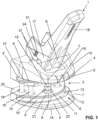
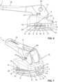
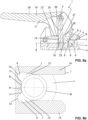
- the figures show a bending device 1 according to an embodiment of the present invention.
- the figures also show an actuating arrangement 17.
- the bending device 1 can be designed with the actuating arrangement 17. Both the actuating arrangement 17 and the bending device 1 can be designed independently of one another.
- the actuating arrangement 17 can be used in other devices not shown here, and the bending device 1 can be actuated with other actuating arrangements not shown here.
- the bending device 1 is used to bend a pipe R with an insulation jacket I.
- the pipe R is typically made of metal or a composite material with metal and plastic.
- the insulation jacket I is made of foam.
- the insulation jacket I surrounds the outside of the pipe R and typically extends over its entire length.
- Bending device 1 comprises a bending die arrangement 2 with at least one bending die 3.
- the bending die 3 comprises two die parts, namely a first die part 14 and a second die part 15.
- the bending die consists of only one die part.
- the bending die 3 provides a receiving space 6 partially delimited by side walls 4, 5.
- the receiving space 6 has an access opening 7 through which the pipe R with the insulation jacket I can be inserted into the receiving space 6 for the bending process.
- At least one bending surface 8 is arranged in the receiving space 6, which extends partially around a central axis M.
- the pipe R with the insulation jacket I is bent around the bending surface 8.
- the bending surface extends around the central axis M by an angle of at least 90°, in particular of at least 100°.
- the angle is essentially dependent on the desired pipe bending angle. Depending on the material of the pipe, the angle must be slightly larger than the pipe bending angle, because the pipe can spring back after the bending process has taken place.
- the bending die 8 comprises at least one displacement recess 9.
- the at least one displacement recess 9 is arranged such that it enlarges the receiving space 6 so that the insulation jacket I can be displaced into the displacement recess 9 during the bending process.
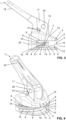
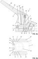
- the displacement of the insulation jacket I is shown accordingly.
- the pipe R in the Figures 5a, 5b has a larger diameter than the pipe R in the Figures 8a, 8b .
- the insulation jacket I is displaced into the at least one displacement recess 9. This means that the insulation jacket I flows into the at least one displacement recess 9.
- the pipe R lies indirectly on the bending surface 8 via the insulation jacket I, with the insulation jacket I being compressed at this point.
- the insulation jacket I not only extends into the at least one displacement recess 9, but is also displaced outwards via the access opening 7.
- the at least one displacement recess 9 extends along the at least one bending surface 8. This means that the at least one displacement recess 9 is located adjacent to the bending surface 8. In the embodiment shown, the displacement recess 9 merges with the bending surface 8 via a convex curve 10. In the embodiment shown, two bending surfaces 8 and two displacement recesses 9 are arranged. The two bending surfaces 8 are located between the two displacement recesses 9.
- the receiving space 6 has, as seen from the access opening 7, an upper side wall 4, a lower side wall 5 located at a distance from the upper side wall 4, and a rear wall 11 which closes off the receiving space 6 towards the rear and is located opposite the access opening 7.
- the two side walls 4, 5 extend from the access opening 7 to the rear wall 11.
- the displacement recesses 9 extend, as seen from the receiving space 6, into the respective side wall 4, 5 and into the rear wall 11.
- the displacement recesses 9 are located in the region of the transition from the side wall 4, 5 to the rear wall 11.
- the bending surface 11 is also located on the rear wall 11 or, depending on the design of the bending surface 11, the bending surface 11 is provided by the rear wall.
- the displacement recess 9 extends here in cross section along the central axis in a first section 12 as a conical surface segment and in a second section 13 extends as a rounded surface segment.
- the conical surface segment is positioned such that the clear width between the two displacement recesses 9 increases with increasing depth from the access opening 7 into the receiving space 6.
- the rounded surface segment is designed as a concave curve. The rounded surface segment merges with the convex curve 10 to the bending surface 8.
- the receiving space 6 has a cross-section, as seen from the access opening 7, which is constant up to the beginning of the first section and then widens due to the displacement recess 9. Due to the constant cross-section, the pipe R with the insulation jacket I can be easily guided along the bending surface 8 during the bending process. The pipe R slides further into the receiving space 6 with increasing degree of bending.
- the cross-section of the displacement recess 9 is substantially constant over its entire length around the central axis M.
- the displacement recess 9 preferably runs in such a way that its cross-section becomes continuously smaller with decreasing distance from the beginning or the end.
- the bending die 3 is designed in two parts with a first die part 14 and a second die part 15.
- the two die parts 14, 15 can be moved from a starting position to a bending position towards each other and then moved away from each other again from the bending position to the starting position.
- the starting position is shown.
- the pipe R with the insulation jacket I can be inserted into the receiving space 6 via the access opening 7.
- the two die parts are then moved into the bending position and the pipe R can be bent.
- the insulation jacket I is continuously displaced into the displacement recess 9.
- the first die part 14 lies on one side of an imaginary plane E and the second die part 15 lies on another side of the imaginary plane E.
- the imaginary plane E extends at right angles to the central axis M and centrally through the receiving space 6.
- each die part 14, 15 has a bending surface 8 and a displacement recess 9.
- the two die parts 14, 15 are connected to one another via a guide structure 16.
- the guide structure 16 here has several guide pins via which the die parts 14, 15 are connected.
- the upper die part 14 is movable with respect to the guide pins, and the lower die part 15 is fixedly mounted to the guide pins.
- the two die parts 14, 15 can be moved towards one another from the starting position into the bending position via an actuating arrangement 17 with an actuating element 18. Furthermore, the guide structure 16 preferably has a return element 19 which pushes the two die parts 14, 15 away from one another. When the actuation with the actuating element 18 is no longer used, the two die parts 14, 15 are returned to the starting position by the return element 19. As mentioned, the die parts 14, 15 are in the starting position before the pipe R is inserted into the receiving space 6, and the die parts 14, 15 are moved towards one another into the bending position before the bending process, such that the insulation I of the inserted pipe R is partially compressed and partially pressed into the displacement recess, and that the pipe R is held by the die parts 14, 15.
- the die parts 14, 15 are positioned relative to each other depending on the pipe diameter.
- the die parts 14, 15 are spaced apart from one another in the bending position and, with the smaller diameter, the two die parts 14, 15 are in contact with one another in the bending position via contact surfaces 20.
- the actuating arrangement 17 comprises a bearing rod 21 which extends along a bearing rod axis L and is connected to the first die part 14 via a bearing section 22 and extends through an opening 23 on the second die part 15, and a pivot rod 24 which extends along a pivot rod axis S and which is arranged on the bearing rod 21 opposite the bearing section 22.
- the pivot rod axis S is perpendicular to the bearing rod axis L.
- the actuating element 18 is pivotably connected to the pivot rod 24.
- the actuating element 18 has an opening 32 into which the pivot rod 24 projects.
- the actuating element 18 has a contact surface 25. With the contact surface 15, the actuating element 18 acts on an actuator surface 26 on the second die part 15.
- the contact surface 25 has at least two surface segments 27, 28, the distance of which from the pivot rod axis S is different, such that when one surface segment 27 is in contact with the actuator surface 26, the distance between the die parts 14, 15 is different than when another of the surface segments 28 is in contact with the actuator surface 26. This is due to the Figures 5a and 8a clearly visible.
- the actuating element 18 has a lever portion 29.
- the lever portion 29 can be grasped by a user and pivoted about the pivot axis S.
- the surface segments 27, 28 are designed as flat surface segments.
- a design as rounded surface segments is also conceivable.
- a transition surface 30 is arranged between the surface segments 27, 28, wherein the transition surface 30 is rounded with a curve, wherein the curve is formed such that the distance between the curve and the pivot rod axis S preferably changes continuously between the two surface segments 27, 28.
- the actuating element 18 has at least one marking 31 which, when the actuating element 18 is in a corresponding position, specifies the distance between the two die parts 14, 15.
Landscapes
- Engineering & Computer Science (AREA)
- Mechanical Engineering (AREA)
- Bending Of Plates, Rods, And Pipes (AREA)
Priority Applications (1)
| Application Number | Priority Date | Filing Date | Title |
|---|---|---|---|
| EP23162871.0A EP4434650A1 (fr) | 2023-03-20 | 2023-03-20 | Dispositif de cintrage |
Applications Claiming Priority (1)
| Application Number | Priority Date | Filing Date | Title |
|---|---|---|---|
| EP23162871.0A EP4434650A1 (fr) | 2023-03-20 | 2023-03-20 | Dispositif de cintrage |
Publications (1)
| Publication Number | Publication Date |
|---|---|
| EP4434650A1 true EP4434650A1 (fr) | 2024-09-25 |
Family
ID=85704601
Family Applications (1)
| Application Number | Title | Priority Date | Filing Date |
|---|---|---|---|
| EP23162871.0A Pending EP4434650A1 (fr) | 2023-03-20 | 2023-03-20 | Dispositif de cintrage |
Country Status (1)
| Country | Link |
|---|---|
| EP (1) | EP4434650A1 (fr) |
Citations (13)
| Publication number | Priority date | Publication date | Assignee | Title |
|---|---|---|---|---|
| US3023650A (en) * | 1960-02-01 | 1962-03-06 | Marie C Sterner | Hand-operated tube-bending machine |
| US4132100A (en) * | 1976-04-07 | 1979-01-02 | Schuler Jacob P | Hand-operated tool for bending pipes |
| GB2226268A (en) * | 1988-12-13 | 1990-06-27 | Lee Chin Piao | A paper-perforator |
| US5142895A (en) * | 1989-05-15 | 1992-09-01 | Amana Refrigeration, Inc. | Method for bending tubes |
| US5337590A (en) * | 1993-12-27 | 1994-08-16 | Schuchert Eugene H | Method and apparatus for bending tubes using split bend die |
| EP0878250A2 (fr) * | 1997-05-13 | 1998-11-18 | Megatronic Schweissmaschinenbau GmbH | Endroit de pliage d'un tube metallique à parois mince et appareil pour plier un tel endroit |
| CN2467222Y (zh) * | 2001-02-18 | 2001-12-26 | 王福华 | 多功位铝合金手动冲压机 |
| US20080110223A1 (en) * | 2006-11-15 | 2008-05-15 | Benteler Automobiltechnik Gmbh | Bending device for a tubular member |
| DE102008031276A1 (de) * | 2008-07-02 | 2010-01-07 | Benteler Automobiltechnik Gmbh | Biegewerkzeug und Faltenglätter für ein Biegewerkzeug |
| US20110314982A1 (en) * | 2009-03-06 | 2011-12-29 | Nitta Corporation | Sheet cutter and belt processing tool |
| US8375764B2 (en) | 2010-10-07 | 2013-02-19 | Chang Yang Huang | Pipe bender |
| CN110064684A (zh) * | 2018-01-24 | 2019-07-30 | 宁波兴业盛泰集团有限公司 | 一种金属带材折弯机及其折弯工艺 |
| WO2020100048A1 (fr) * | 2018-11-16 | 2020-05-22 | Cml International S.P.A. | Machine pour plier une pièce allongée sans formation de rides |
-
2023
- 2023-03-20 EP EP23162871.0A patent/EP4434650A1/fr active Pending
Patent Citations (13)
| Publication number | Priority date | Publication date | Assignee | Title |
|---|---|---|---|---|
| US3023650A (en) * | 1960-02-01 | 1962-03-06 | Marie C Sterner | Hand-operated tube-bending machine |
| US4132100A (en) * | 1976-04-07 | 1979-01-02 | Schuler Jacob P | Hand-operated tool for bending pipes |
| GB2226268A (en) * | 1988-12-13 | 1990-06-27 | Lee Chin Piao | A paper-perforator |
| US5142895A (en) * | 1989-05-15 | 1992-09-01 | Amana Refrigeration, Inc. | Method for bending tubes |
| US5337590A (en) * | 1993-12-27 | 1994-08-16 | Schuchert Eugene H | Method and apparatus for bending tubes using split bend die |
| EP0878250A2 (fr) * | 1997-05-13 | 1998-11-18 | Megatronic Schweissmaschinenbau GmbH | Endroit de pliage d'un tube metallique à parois mince et appareil pour plier un tel endroit |
| CN2467222Y (zh) * | 2001-02-18 | 2001-12-26 | 王福华 | 多功位铝合金手动冲压机 |
| US20080110223A1 (en) * | 2006-11-15 | 2008-05-15 | Benteler Automobiltechnik Gmbh | Bending device for a tubular member |
| DE102008031276A1 (de) * | 2008-07-02 | 2010-01-07 | Benteler Automobiltechnik Gmbh | Biegewerkzeug und Faltenglätter für ein Biegewerkzeug |
| US20110314982A1 (en) * | 2009-03-06 | 2011-12-29 | Nitta Corporation | Sheet cutter and belt processing tool |
| US8375764B2 (en) | 2010-10-07 | 2013-02-19 | Chang Yang Huang | Pipe bender |
| CN110064684A (zh) * | 2018-01-24 | 2019-07-30 | 宁波兴业盛泰集团有限公司 | 一种金属带材折弯机及其折弯工艺 |
| WO2020100048A1 (fr) * | 2018-11-16 | 2020-05-22 | Cml International S.P.A. | Machine pour plier une pièce allongée sans formation de rides |
Similar Documents
| Publication | Publication Date | Title |
|---|---|---|
| DE69705851T2 (de) | Vorrichtung zum richten von draht | |
| DE69215724T2 (de) | Wendeschneidplatte | |
| EP3718184A2 (fr) | Mâchoires de serrage et bords tranchants pour pince à dénuder ainsi que pince à dénuder | |
| DE2715178A1 (de) | Handwerkzeug zum biegen von rohren | |
| WO2019105707A1 (fr) | Pince à dénuder | |
| EP3718186A1 (fr) | Pince à dénuder | |
| EP3587173A1 (fr) | Limiteur de hauteur réglable | |
| DE19817849B4 (de) | Kipphebel | |
| DE68911386T2 (de) | Verriegelungsfeder für Verbinder. | |
| DE2708841C2 (de) | Anschlußklemme für isolierte elektrische Leiter | |
| DE1900741C3 (de) | Vorrichtung zur Formgebung konischer Metallrohre | |
| EP4434650A1 (fr) | Dispositif de cintrage | |
| EP3098357B1 (fr) | Dispositif d'actionnement de soupape de vidange d'un réservoir de chasse | |
| DE4231564C2 (de) | Buchsenkontakt mit einem Anker | |
| EP0337301A1 (fr) | Agrafe de fermeture pour enveloppes de saucisson et similaires | |
| EP1183114B1 (fr) | Mandrin de cintrage pour un dispositif de cintrage, et procede de cintrage de tuyaux | |
| AT400544B (de) | Stanzzange | |
| EP0675564B1 (fr) | Contact auto-dénudant oblique | |
| DE3508939A1 (de) | Elektrische klemme | |
| DE202006014527U1 (de) | Seitenschneider | |
| DE2006109A1 (de) | Vorrichtung zum Biegen von Metallrohren | |
| DE69003021T2 (de) | Isolierender Abstandshalter. | |
| DE69820398T2 (de) | Verfahren zum Stanzen von Schubladenführungen | |
| EP3918699B1 (fr) | Dispositif de cintrage d'au moins une piece conductrice, dans un etat initial en forme de u, et procede correspondant | |
| DE8702746U1 (de) | Vorrichtung zum Entfernen von Isolierung |
Legal Events
| Date | Code | Title | Description |
|---|---|---|---|
| PUAI | Public reference made under article 153(3) epc to a published international application that has entered the european phase |
Free format text: ORIGINAL CODE: 0009012 |
|
| STAA | Information on the status of an ep patent application or granted ep patent |
Free format text: STATUS: THE APPLICATION HAS BEEN PUBLISHED |
|
| AK | Designated contracting states |
Kind code of ref document: A1 Designated state(s): AL AT BE BG CH CY CZ DE DK EE ES FI FR GB GR HR HU IE IS IT LI LT LU LV MC ME MK MT NL NO PL PT RO RS SE SI SK SM TR |
|
| STAA | Information on the status of an ep patent application or granted ep patent |
Free format text: STATUS: REQUEST FOR EXAMINATION WAS MADE |
|
| 17P | Request for examination filed |
Effective date: 20250122 |