EP4434664A1 - Systèmes et procédés d'utilisation de dispositifs d'alimentation en fil en ligne - Google Patents
Systèmes et procédés d'utilisation de dispositifs d'alimentation en fil en ligne Download PDFInfo
- Publication number
- EP4434664A1 EP4434664A1 EP24165683.4A EP24165683A EP4434664A1 EP 4434664 A1 EP4434664 A1 EP 4434664A1 EP 24165683 A EP24165683 A EP 24165683A EP 4434664 A1 EP4434664 A1 EP 4434664A1
- Authority
- EP
- European Patent Office
- Prior art keywords
- welding
- wire feeder
- wire
- line wire
- feeder device
- Prior art date
- Legal status (The legal status is an assumption and is not a legal conclusion. Google has not performed a legal analysis and makes no representation as to the accuracy of the status listed.)
- Pending
Links
Images




Classifications
-
- B—PERFORMING OPERATIONS; TRANSPORTING
- B23—MACHINE TOOLS; METAL-WORKING NOT OTHERWISE PROVIDED FOR
- B23K—SOLDERING OR UNSOLDERING; WELDING; CLADDING OR PLATING BY SOLDERING OR WELDING; CUTTING BY APPLYING HEAT LOCALLY, e.g. FLAME CUTTING; WORKING BY LASER BEAM
- B23K9/00—Arc welding or cutting
- B23K9/12—Automatic feeding or moving of electrodes or work for spot or seam welding or cutting
- B23K9/124—Circuits or methods for feeding welding wire
-
- B—PERFORMING OPERATIONS; TRANSPORTING
- B23—MACHINE TOOLS; METAL-WORKING NOT OTHERWISE PROVIDED FOR
- B23K—SOLDERING OR UNSOLDERING; WELDING; CLADDING OR PLATING BY SOLDERING OR WELDING; CUTTING BY APPLYING HEAT LOCALLY, e.g. FLAME CUTTING; WORKING BY LASER BEAM
- B23K9/00—Arc welding or cutting
- B23K9/12—Automatic feeding or moving of electrodes or work for spot or seam welding or cutting
- B23K9/124—Circuits or methods for feeding welding wire
- B23K9/125—Feeding of electrodes
-
- B—PERFORMING OPERATIONS; TRANSPORTING
- B23—MACHINE TOOLS; METAL-WORKING NOT OTHERWISE PROVIDED FOR
- B23K—SOLDERING OR UNSOLDERING; WELDING; CLADDING OR PLATING BY SOLDERING OR WELDING; CUTTING BY APPLYING HEAT LOCALLY, e.g. FLAME CUTTING; WORKING BY LASER BEAM
- B23K9/00—Arc welding or cutting
- B23K9/12—Automatic feeding or moving of electrodes or work for spot or seam welding or cutting
- B23K9/133—Means for feeding electrodes, e.g. drums, rolls, motors
- B23K9/1336—Driving means
-
- B—PERFORMING OPERATIONS; TRANSPORTING
- B23—MACHINE TOOLS; METAL-WORKING NOT OTHERWISE PROVIDED FOR
- B23K—SOLDERING OR UNSOLDERING; WELDING; CLADDING OR PLATING BY SOLDERING OR WELDING; CUTTING BY APPLYING HEAT LOCALLY, e.g. FLAME CUTTING; WORKING BY LASER BEAM
- B23K9/00—Arc welding or cutting
- B23K9/16—Arc welding or cutting making use of shielding gas
- B23K9/173—Arc welding or cutting making use of shielding gas and of a consumable electrode
-
- B—PERFORMING OPERATIONS; TRANSPORTING
- B23—MACHINE TOOLS; METAL-WORKING NOT OTHERWISE PROVIDED FOR
- B23K—SOLDERING OR UNSOLDERING; WELDING; CLADDING OR PLATING BY SOLDERING OR WELDING; CUTTING BY APPLYING HEAT LOCALLY, e.g. FLAME CUTTING; WORKING BY LASER BEAM
- B23K9/00—Arc welding or cutting
- B23K9/16—Arc welding or cutting making use of shielding gas
- B23K9/173—Arc welding or cutting making use of shielding gas and of a consumable electrode
- B23K9/1735—Arc welding or cutting making use of shielding gas and of a consumable electrode making use of several electrodes
-
- B—PERFORMING OPERATIONS; TRANSPORTING
- B23—MACHINE TOOLS; METAL-WORKING NOT OTHERWISE PROVIDED FOR
- B23K—SOLDERING OR UNSOLDERING; WELDING; CLADDING OR PLATING BY SOLDERING OR WELDING; CUTTING BY APPLYING HEAT LOCALLY, e.g. FLAME CUTTING; WORKING BY LASER BEAM
- B23K9/00—Arc welding or cutting
- B23K9/12—Automatic feeding or moving of electrodes or work for spot or seam welding or cutting
- B23K9/122—Devices for guiding electrodes, e.g. guide tubes
Definitions
- Welding has become increasingly ubiquitous. Welding can be performed in an automated manner or in a manual manner (e.g., being performed by a human). Equipment or components used during welding operations may be driven using engines. For example, engines may be used to drive, for example, generators, power sources, etc. used during welding operations.
- aspects of the present disclosure relate to welding solutions. More specifically, various implementations in accordance with the present disclosure are directed to systems and methods for utilizing in-line wire feeders, substantially as illustrated by or described in connection with at least one of the figures, and as set forth more completely in the claims.
- circuits and “circuitry” refer to physical electronic components (e.g., hardware), and any software and/or firmware (“code”) that may configure the hardware, be executed by the hardware, and/or otherwise be associated with the hardware.
- code software and/or firmware
- a particular processor and memory e.g., a volatile or non-volatile memory device, a general computer-readable medium, etc.
- a circuit may comprise analog and/or digital circuitry. Such circuitry may operate, for example, on analog and/or digital signals.
- a circuit may be in a single device or chip, on a single motherboard, in a single chassis, in a plurality of enclosures at a single geographical location, in a plurality of enclosures distributed over a plurality of geographical locations, etc.
- module may, for example, refer to a physical electronic components (e.g., hardware) and any software and/or firmware (“code”) that may configure the hardware, be executed by the hardware, and/or otherwise be associated with the hardware.
- circuitry or module is "operable" to perform a function whenever the circuitry or module comprises the necessary hardware and code (if any is necessary) to perform the function, regardless of whether performance of the function is disabled or not (e.g., by a user-configurable setting, factory trim, etc.).
- "and/or” means any one or more of the items in the list joined by “and/or”.
- "x and/or y” means any element of the three-element set ⁇ (x), (y), (x, y) ⁇ .
- "x and/or y” means "one or both of x and y.”
- "x, y, and/or z” means any element of the seven-element set ⁇ (x), (y), (z), (x, y), (x, z), (y, z), (x, y, z) ⁇ .
- x, y and/or z means “one or more of x, y, and z.”
- exemplary means serving as a non-limiting example, instance, or illustration.
- terms "for example” and “e.g.” set off lists of one or more non-limiting examples, instances, or illustrations.
- Welding-type power refers to power suitable for welding, plasma cutting, induction heating, CAC-A (carbon arc cutting/air) and/or hot wire welding/preheating (including laser welding and laser cladding).
- Welding-type power supply refers to a power supply that can provide welding-type power.
- a welding-type power supply may include power generation components (e.g., engines, generators, etc.) and/or power conversion circuitry to convert primary power (e.g., engine-driven power generation, mains power, etc.) to welding-type power.
- Welding-type operations comprise operations in accordance with any known welding technique, including flame welding techniques such as oxy-fuel welding, electric welding techniques such as shielded metal arc welding (e.g., stick welding), metal inert gas (MIG) welding, tungsten inert gas (TIG) welding, resistance welding, as well as gouging (e.g., carbon arc gouging), cutting (e.g., plasma cutting), brazing, induction heating, soldering, and/or the like.
- flame welding techniques such as oxy-fuel welding
- electric welding techniques such as shielded metal arc welding (e.g., stick welding), metal inert gas (MIG) welding, tungsten inert gas (TIG) welding, resistance welding, as well as gouging (e.g., carbon arc gouging), cutting (e.g., plasma cutting), brazing, induction heating, soldering, and/or the like.
- flame welding techniques such as oxy-fuel welding
- electric welding techniques such as shielded
- Welding-type setup refers to any setup comprising welding related devices or equipment (e.g., welding power sources, welding torch, welding gear such as headwear and the like, auxiliary devices or systems, etc.) which are used in facilitating and/or in conjunction with welding-type operations.
- welding related devices or equipment e.g., welding power sources, welding torch, welding gear such as headwear and the like, auxiliary devices or systems, etc.
- FIG. 1 shows an example welding-type setup that may be used for welding-type operations.
- an example welding-type setup 10 in which an operator (user) 18 is wearing welding headwear 20 and welding a workpiece 24 using a torch 30 to which power is delivered by equipment 12 via a conduit 14, with weld monitoring equipment 28, which may be available for use in monitoring welding operations.
- the equipment 12 may comprise a power source, optionally a source of a shield gas and, where wire/filler material is to be provided automatically, a wire feeder.
- an engine 32 may be used to drive equipment or components used during welding operations.
- the engine 32 may comprise a gas engine or a liquefied petroleum (LP) engine.
- the engine 32 may drive generators, power sources, etc. used during welding operations.
- the welding-type setup 10 of FIG. 1 may be configured to form a weld joint by any known welding-type technique.
- the welding equipment 12 may be arc welding equipment that provides a direct current (DC) or alternating current (AC) to a consumable or non-consumable electrode of a torch 30.
- the electrode delivers the current to the point of welding on the workpiece 24.
- the operator 18 controls the location and operation of the electrode by manipulating the torch 30 and triggering the starting and stopping of the current flow.
- a robot or automated fixture may control the position of the electrode and/or may send operating parameters or trigger commands to the welding system. When current is flowing, an arc 26 is developed between the electrode and the workpiece 24.
- the conduit 14 and the electrode thus deliver current and voltage sufficient to create the electric arc 26 between the electrode and the workpiece.
- the arc 26 locally melts the workpiece 24 and welding wire or rod supplied to the weld joint (the electrode in the case of a consumable electrode or a separate wire or rod in the case of a non-consumable electrode) at the point of welding between electrode and the workpiece 24, thereby forming a weld joint when the metal cools.
- the weld monitoring equipment 28 may be used to monitor welding operations.
- the weld monitoring equipment 28 may be used to monitor various aspects of welding operations, particularly in real-time (that is as welding is taking place).
- the weld monitoring equipment 28 may be operable to monitor arc characteristics such as length, current, voltage, frequency, variation, and instability. Data obtained from the weld monitoring may be used (e.g., by the operator 18 and/or by an automated quality control system) to ensure proper welding.
- the equipment 12 and headwear 20 may communicate via a link 25 via which the headwear 20 may control settings of the equipment 12 and/or the equipment 12 may provide information about its settings to the headwear 20.
- a link 25 via which the headwear 20 may control settings of the equipment 12 and/or the equipment 12 may provide information about its settings to the headwear 20.
- the link may be wireless, wired, or optical.
- equipment or components used during welding operations may be driven using engines.
- the engine 32 may drive generators, power sources, etc. used during welding operations.
- data relating to engines (and operations thereof) used during welding operations may be collected and used (e.g., based on analysis thereof) in monitoring and optimizing operations of these engines.
- the collection and use of such data may be performed telematically-that is, the data may be collected locally, subjected to at least some processing locally (e.g., formatting, etc.), and then may be communicated to remote management entities (e.g., centralized management locations, engine providers, etc.), using wireless technologies (e.g., cellular, satellite, etc.).
- a dedicated controller may be used to control, centralize, and/or optimize data handling operations.
- the controller 34 may comprise suitable circuitry, hardware, software, or any combination thereof for use in performing various aspects of the engine related data handling operations.
- the controller 34 may be operable to interface with the engine 32 to obtain data related thereto.
- the controller 34 may track or obtain welding related data (e.g., from weld monitoring equipment 28, from equipment 12, etc.).
- the controller 34 may then transmit the data (e.g., both engine related and weld related data), such as to facilitate remote monitoring and/or management, by way of wireless communications. This may be done using cellular and or satellite telematics hardware, for example.
- welding-type systems or setups such as the welding-type setup 10, may be configured for collecting and reporting data relating to welding-type operations and/or to functions or components utilized during welding-type operations. For example, data from welding processes, power sources, welding-related accessories etc. in a weld setup may be collected.
- the collected data may comprise, for example, current, voltage, wire feed speed, weld states, and numerous other power source parameters and settings.
- the collected data may then be sent to remote entities (e.g., a remote server 31, which may be a manufacturer-controlled, Internet-based cloud server) and/or to local systems or devices (e.g., local PC, a tablet, a smartphone, etc.).
- remote entities e.g., a remote server 31, which may be a manufacturer-controlled, Internet-based cloud server
- local systems or devices e.g., local PC, a tablet, a smartphone, etc.
- the collected data may be utilized in enhancing welding-related systems and/or operations. For example, manufacturers may utilize the collected data to identify issues (and correct them) and/or devise modifications or improvements in the various components. Further, users may be able to generate reports on collected data to measure, document, and improve their processes.
- FIG. 1B shows an example metal inert gas (MIG) welding based setup that may be used for MIG based welding-type operations.
- MIG metal inert gas
- the welding-type setup 100 represents an example metal inert gas (MIG) welding based implementation of the welding-type setup 10 of FIG. 1 .
- the MIG based welding-type setup 100 comprises a gas supply unit 110, a power supply unit 120, and a welding torch (gun) 160.
- the power supply unit 120 comprises a weld power source 130, a wire feeder unit 140, and a wire source (e.g., wire spool) 150.
- the disclosure is not limited to such arrangement, and as such, some of the components of the power supply unit 120 as shown in FIG. 1B -namely, the wire feeder unit 140 and/or the wire source 150-may be separate physical components.
- the welding-type setup 100 may be used to apply MIG based welds, such to workpieces (e.g., workpiece 170 shown in FIG. 1B ).
- MIG based welding a consumable electrode wire is fed from the wire source 150, via the wire feeder unit 140, through the torch 160, as an electric arc is formed between the consumable electrode wire and the workpiece 170 as a current is supplied by the power supply unit 120 to both of the torch 160 and the workpiece 170, with the weld power source 130 providing that power, as well as providing power to other components of the power supply unit 120, such as to the wire feeder unit 140 to facilitate the wire feeding thereby.
- a shielding gas is fed from the gas supply unit 110 through the torch 160, to shield the weld (e.g., from atmospheric contamination).
- a single connector between the power supply unit 120 and the welding torch (gun) 160 may be used to provide the electrode wire, the shielding gas, and power from the power supply unit 120 to the welding torch (gun) 160. Nonetheless, the disclosure is not limited to such design, and as such in some implementations separate dedicated connectors may be used providing one or more of the electrode wire, the shielding gas, and power.
- MIG based welding may be pose some challenges and/or may have some limitations, however.
- one of the main limitations when using MIG based welding is the distance between the power source (e.g., the combination of the gas supply unit 110, the wire feeder unit 140, the power supply unit 120, and the wire source 150) and the work site-that is, where the weld is being applied, such as the location of the workpiece 170.
- the power source e.g., the combination of the gas supply unit 110, the wire feeder unit 140, the power supply unit 120, and the wire source 150
- the work site-that where the weld is being applied, such as the location of the workpiece 170.
- one of the main limitations and/or challenges when using MIG guns is the maximum distance (or lead) from the work site to the power source that the user may move without needing to re-position the power source.
- the typical lead in the industry for a single drive system is ⁇ 10 ft.
- users may desire a longer lead on the gun; providing such longer lead
- the challenge with providing longer gun lead is limiting what wire diameter that can be pushed through longer lead, which may increase the friction between the liner and the wire.
- Such increased friction may force the users to increase the tension on the drive roll.
- the increased tension may in turn cause some issues.
- the increased tension may deform the wire cross section.
- with the increase friction and tension may cause the wire to collapse and start nesting inside the drive compartment.
- the wire material may affect the lead distance, and thus may be another limiting factor.
- achieving longer leads with aluminum based wires may be particularly challenging because of the limited column strength of aluminum.
- the column strength of aluminum may limit how much aluminum wire can be pushed-e.g., allowing for only a short lead distance before issues may occur, such as the aluminum wire binding up inside with the liner.
- spool gun which incorporate a wire source (e.g., 4 inch spool) and wire feed mechanism) attached directly to the gun.
- wire source e.g., 4 inch spool
- push-pull gun which pull the wire out from the power source and pushes it through the gun.
- spool guns may be challenging and undesirable due to the strain use of such gun may have on the user (e.g., causing strain on the user's wrist).
- size and shape of the spool gun also limits the user from getting into tight spaces.
- the push-pull gun may be lighter and smaller in size, it is very expensive and it imposes strict operation requirements-e.g., the feeding mechanism/components (e.g., motors) in the two devices (the push-pull gun and the supply unit) have to be synchronized and must operate in harmony to ensure proper feeding of the wire since the push-pull gun needs to pull the wire from the power supply unit and then push it in synchronized manner (e.g., the motors must operate at the same rate of speed, to prevent jamming).
- the feeding mechanism/components e.g., motors
- solutions based on the present disclosure address some of the challenges of existing welding systems, particularly with respect to short leads, while overcoming the limitations of any existing conventional solutions.
- solutions based on the present disclosure may allow for increasing leads during welding operations, particularly by use of a separate wire feeder (referred to as "in-line wire feeder") configured to optimize performance.
- in-line wire feeders based on the present disclosure may enable addressing issues relating to or limitations on distance between the worksite to power supply, particularly by separating the wire feeding mechanism from the power source, to enable moving the wire feeding mechanism closer to the worksite, thus extending the overall distance between the worksite to power supply.
- an in-line wire feeder may be provided as a separate physical device, which may incorporate a wire feeding mechanism, along with additional components and/or features that may be needed for supporting operation thereof, with such in-line wire feeders being configured for use as separate device in suitable welding-type setups, to provide longer leads.
- the in-line wire feeder may be configured to connect to gas, wire, and power sources on one end, such as via first-side connecter(s), and to connect to a torch (e.g., MIG gun) on the other end, such as via second-side connector(s), thus allowing for greater distances between the torch and the power supply than is possible in conventional setups.
- a torch e.g., MIG gun
- the in-line wire feeder may be placed at first distance (e.g., up to ⁇ 20 ft.) away from a power supply unit, and the user may then add another, second distance (e.g., up to -10-12 ft.) from the torch (e.g., MIG gun) to the in-line wire feeder, thus extending the overall reach while still pulling the electrode wire out of power supply unit (or wire source).
- first distance e.g., up to ⁇ 20 ft.
- second distance e.g., up to -10-12 ft.
- the in-line wire feeder may be used as an accessory device that may work with, and be plugged into existing power supply equipment.
- the electrode wire then may be routed through the wire feeder at the power supply equipment, with the wire feeding mechanism in the in-line wire feeder handling the feeding the wire to the torch.
- the in-line wire feeder may be configured to work in conjunction with a wire feeder (referred to as "second wire feeder device” or “second wire feeder”) that provides the wire feeding functions in conventional designs (e.g., the wire feeder integrated into the power supply unit, or a detached wire feeder that is used with the power supply unit).
- second wire feeder device referred to as "second wire feeder device” or “second wire feeder”
- Example arrangements are illustrated and described with respect to FIG. 1C .
- an in-line wire feeder may be connected between the torch 160 and the power supply unit 120, or (alternatively) the wire-feed unit 140 may be separated from the remaining part of the power supply in the welding-type setup 100-that is, the wire source 150, the power supply unit 120, and the gas supply unit 110-and moved placed closer to the worksite.
- the in-line wire feeder may be designed or configured such that it to be carried by or otherwise be attached to the user (or a piece of equipment or clothing used by the user).
- the in-line wire feeder may incorporate holstering or strapping components (e.g., shoulder harness, belt, etc.), or may be configured (e.g., by incorporating suitable attachment features) such that may be attached to separate holster or strapping systems and/or to engage existing holster or strapping systems (e.g., tool belts) that users may already be using. Carrying or holstering the in-line wire feeder may be done in conjunction with use of a shorter gun, which may allow the user to push alternate material like aluminum or smaller diameter steel wire.
- the in-line wire feeder(s) instead may be configured to be placed off of the user's body-e.g., simply placed on the ground/floor, or may be configured such that they may be attached or secured to something else, such as a fixed structure or object (e.g., a dedicated stand, or any available structure or object, such as a desk or a railing) near the worksite.
- a fixed structure or object e.g., a dedicated stand, or any available structure or object, such as a desk or a railing
- the in-line wire feeder may incorporate features or components to allow mounting it or otherwise attaching to existing structures (e.g., using magnetic mechanism, such as to a table, railing, etc.).
- the in-line wire feeder may incorporate strap mounts or hook-like parts that enable the user to mount the in-line wire feeder off the floor.
- the in-line wire feeder(s) may be configured such that it would allow the user to easily detach the in-line wire feeder(s).
- the attaching mechanism may also be configured to optimize or enhance operation.
- the holster or strapping system may be configured such that it may rotatable and repositionable.
- the holster or strapping system also may be configured or designed to limit the reduction in the bend radius. Such bend radius may be desirable as a tighter bend radius could result in difficulty of feeding the wire.
- separate connectors may be used for power, gas, and wire, such as to enable use of separate wire source that may be connected directly via dedicated connector, with the power supply unit providing only power (and optionally gas) and thus omits the wire feeding therefrom.
- the in-line wire feeder may incorporate controls (e.g., suitable input means), which allows the user to control the wire feeding.
- the in-line wire feeder may also incorporate a transparent section to allow the user to see the wire as it emerges into the in-line wire feeder.
- the in-line wire feeder may incorporate an input device configured to receive user input. The input device may provide, based on the user input, control input for controlling, at least in part, one or both of the feeding of the wire and the feeding mechanism in the in-line wire feeder.
- the input device may be configured to provide, based on the user input, control input for adjusting feeding speed related parameters.
- the input device may be a switch (e.g., momentary switch) that controls one or both of the second wire feeder device and the in-line wire feeding mechanism, with the controlling including, while the switch is pressed or otherwise activated, deactivating the in-line wire feeding mechanism and activating the feeding function of the external (second) wire feeder device.
- a switch e.g., momentary switch
- the in-line wire feeder may incorporate a speed regulating component, which may be configured to adjust feeding speed related parameters of the in-line wire feeding mechanism. This may be done by, e.g., adjusting gear ratios wire feeding mechanism in the in-line wire feeder.
- a speed regulating component may be advantageous to ensure that the in-line wire feeder may be simulate operation of a gun (e.g., spool gun)-that is, to ensure that the feeding speed applied at the in-line wire feeder matches the feeding speed when using existing guns.
- an alternate design may be used, with configurable in-line wire feeder(s). This may be done to allow a user to choose a wire source (e.g., wire spool) that may be integrated with the wire drive/feeding mechanism in the in-line wire feeder, attach the wire source as a separate element in the system, or keep the wire source internal to the power source.
- a wire source e.g., wire spool
- solutions based on the present disclosure, and systems associated therewith may have various advantages over conventional solutions (if any existed).
- the proposed solutions and systems associated therewith incorporating separate in-line wire feeders as described herein, allow for extended lead length with reduced concern of pushing thinner gauge wire or softer material.
- the proposed solutions and systems associated therewith allow for use of existing torches (MIG guns), which in turn allows for and ensures light weight on wrist, which would be advantageous to the users.
- MIG guns existing torches
- the proposed solutions and systems associated therewith also have the advantage of allowing for (re-)use of common consumables of existing MIG guns.
- the proposed solutions and systems associated therewith may also allow for improved operation due to the system's light weight and flexibility of use, thus allowing for welding in tighter areas and/or confined spaces.
- the proposed solutions and systems associated therewith may provide enclosure with optimal characteristics-e.g., the shape and/or material used for enclosure may allow for handling the wire drive system in manner to may be preferable by users, as the wire drive system may laid on the floor, dragged, rolled with ease, and/or oriented to minimize the cable bend for improved feeding.
- the proposed solutions and systems associated therewith may also be backwards compatible with existing, welding related systems.
- the machine e.g., power supply unit
- the machine may be configured to (e.g., by operating in a certain mode) feed out a certain length of wire (e.g., ⁇ 10 ft.) and then the machine stops till welding commences. This require holding the line straight to prevent binding up in the line.
- the wire feeder in the machine operate to continually feed the wire, and with spool gun based setups, the motor of the wire feeder in the machine must operate in synchronized manner with the motor of the spool gun.
- physical attributes of the in-line wire feeder may be selected or adjusted to optimized or enhance operation and/or use thereof.
- shape of the in-line wire feeder may have smooth, football (oval) shape.
- Such shape may offer various benefits and/or advantages.
- one advantage of this shape is having a single point of contact with the floor, which makes it easy to drag the in-line wire feeder.
- Another advantage is that the smooth shape also allows for pull over other obstacles (e.g., cords or the like) which may be laying on the floor. Nonetheless, it should be assumed that the disclosure is limited the shape(s) illustrated in the accompanying figures, and a person of ordinary skill in art should appreciate that any suitable shape (or size) may be used.
- Example implementation(s) based on the present disclosure and additional details related thereto are described in more detail below with respect to FIGS. 2-4 .
- FIG. 1C illustrated alternative example arrangements for incorporating an in-line wire feeder.
- example welding-type setups 180 and 182 which represent modified arrangement of the welding-type setup 100 to incorporate use of an in-line wire feeder implemented based on the present disclosure, as described herein.
- the setup 180 illustrates use of an in-line wire feeder in conjunction with an integrated second wire feeder-that is, where the second (external) wire feeder (and the wire source-e.g., wire spool) is integrated within the power supply unit.
- the setup 180 illustrates use of an in-line wire feeder in conjunction with a detached (external) second wire feeder-that is, where the second (external) wire feeder (and the wire source-e.g., wire spool) is separate from and externa to the power supply unit that is used to provide power and/or shielding gas to the in-line wire feeder.
- the second (external) wire feeder and the wire source-e.g., wire spool
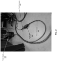
- FIG. 2 illustrates an example in-line wire feeder and use thereof in an example welding-type setup.
- FIG. 2 there is shown an example in-line wire feeder 200 that is incorporated into a MIG based welding-type setup.
- the in-line wire feeder 200 may be configured to provide wire feed during welding-type operations, particularly MIG based welding, and to do so in accordance with the present disclosure such that it may allow for longer leads while overcoming the limitations of any existing conventional solutions.
- welding-type operations particularly MIG based welding
- the in-line wire feeder 200 may be implemented as a separate physical device, comprising a wire feeding system (e.g., components similar and/or equivalent to the wire feeder unit 140 in the welding-type setup 100), and may be configured to support being connected to a power supply unit 210 (e.g., comprising components similar and/or equivalent to the combination of the power supply unit 120 and (optionally) the gas supply unit 110 in the welding-type setup 100) at one end, such as via one or more first-side connectors (e.g., the power connector 230), and to a torch (not shown, e.g., a MIG gun) at other end, such as via one or more second-side connectors (e.g., torch connector 220), thus allowing for greater distances between the torch and the power supply than is possible in conventional setups, as described herein.
- a wire feeding system e.g., components similar and/or equivalent to the wire feeder unit 140 in the welding-type setup 100
- a power supply unit 210 e.g.
- the in-line wire feeder 200 may incorporate one or more first-side ports or outlets, configured to receive or otherwise engage the one or more first-side connectors, and one or more second-side ports or outlets, configured to receive or otherwise engage the one or more second-side connectors.
- the power connector 230 may be used to feed the electrode wire, as well as power and gas, from the power supply unit 210 to the inline wire feeder 200
- the torch connector 220 may enable feeding the electrode wire, as well as (optionally) power and gas, from the in-line wire feeder 200 into the torch.
- any suitable connector may be used.
- the power connector 230 may be conventional spool gun connectors (thus allowing for backward compatibility with existing power supply units), since the in-line wire feeder 200 may generally operate in similar manner as spool gun may operate (though the control of feeding may be adjusted, as described herein), and as such may be connected to and handled by the power supply unit 210 as if it was a spool gun.
- an alternate design may be used, with the wire being fed from separate and/or auxiliary wire source (e.g., wire spool) used, which may be fed via separate and/or auxiliary wire feeder, and as such the in-line wire feeder 200 may incorporate means to enabling connecting such auxiliary wire feeder/source directly, such as via a separate connector.
- auxiliary wire source e.g., wire spool
- Such designs may require use of additional components, such as a suitable connector/receptor and (optionally) separate control circuit(s) in the in-line wire feeder to manage interactions with such wire sources, but would allow the system to be independent with respect to the wire source required thereby.
- an alternate design may be used, with power required to operate the proposed in-line wire feeders (e.g., to run motor(s) used therein) being obtained from separate and/or auxiliary power sources.
- the proposed in-line wire feeders are powered by the power supply unit (e.g., via the power connector 230)
- the disclosure is not limited to such designs, and as such in some implementations, the in-line wire feeder can be powered separately, such as via power connector to an outlet or other suitable power source in the area.
- Such designs may require use of additional components, such as a power connector/receptor and separate power control circuit(s) in the in-line wire feeder, but would allow the system to be independent with respect to the power supply required thereby, and thus resolve backward compatibility concerns.
- the in-line wire feeder may be configured to provide wire based on control input.
- the in-line wire feeder may receive motor speed control.
- the delivery of the filler metal e.g., welding wire
- Such control may be, e.g., in the form of the speed at which the wire is fed.
- WFS wire feed speed
- WFS is a function of the wire feed motor speed, which is dependent upon the voltage supplied to the armature of the motor.
- the in-line wire feeder (e.g., the in-line wire feeder 200) may be configured to receive the motor control voltage from a WFS control circuit in the welding power supply (e.g., welding power supply 210).
- the motor control voltage may be delivered using existing or dedicated connectors or cables in the welding-type system or setup.
- the voltage may be delivered by two of four control wires that are connected to the welding power supply via a 4-pin connector and are coaxially embedded in the power cable (e.g., the power connector 230) that goes back to the welding power supply.
- the other two wires may be used for other control input, such as the gun trigger.
- the other two wires in such 4-wire arrangement may be used as the gun trigger signal leads, which carry the signal(s) for enabling/disabling the welder power output.
- the trigger signal from the welding gun trigger may be passed through these leads to the welding power supply.
- the welding gun trigger is connected to the 4-pin torch-side connector, as shown Figs. 2-4 .
- the WFS control is set at the welder and is transmitted to the motor armature in the feeder.
- the disclosure is not limited to such implementation for motor control scheme, and any other suitable implementation may be used.
- a motor control circuit may be added, such as in the feeder itself, so that the WFS may be controlled remotely.
- such implementation would require the addition of control circuitry and a WFS knob on the feeder.
- the motor control would be set at maximum at the power source and the control in the feeder would attenuate it to the desired level.
- full motor control functionality may be incorporated and/or built into the feeder, with that full motor control functionality powered from, e.g., the welding arc.
- Such scheme would provide a full remote control of the WFS that wouldn't be dependent on the setting of the WFS at the welder.
- Such scheme would also enable the feeder to be used on welders that don't have the typical spool gun style of control (e.g., via the 4-pin connector as described above).
- Such scheme may particularly adaptable for use in welding-type systems or setup that are driven using batteries (or similar power storage devices), and/or which may not have an internal wire feed speed control.
- FIG. 3 illustrates an example in-line wire feeder and features associated therewith.
- the in-line wire feeder 200 described with respect to FIG. 2 .
- illustrated in FIG. 3 are some of the features and/or component of the in-line wire feeder 200 in accordance with an example embodiment thereof.
- the in-line wire feeder 200 may incorporate a transparent cover (window) 310 which exposes the interior of the in-line wire feeder 200, thus showing a feeding mechanism 300 that feeds into the torch (not shown) via the torch connector 220.
- a transparent cover (window) 310 which exposes the interior of the in-line wire feeder 200, thus showing a feeding mechanism 300 that feeds into the torch (not shown) via the torch connector 220.
- the side incorporating the window (or another side) of the in-line wire feeder may incorporate a removable cover to enable accessing the interior of the in-line wire feeder, particularly the wire feeding mechanism 300 (e.g., to resolve such issues as jamming or the like).
- the torch connector 220 and the power connector 230 which connect the in-line wire feeder 200 to, respectively, the torch (not shown) and the power supply unit 210.
- a torch-side control connector 320 may be used, being plugged into or otherwise coupled to the in-line wire feeder 200, such as control messaging and/or data may exchange with the torch, such as to enable controlling the feeding mechanism 300 (e.g., based on user input at the torch, which may be communicated to the in-line wire feeder 200 via the torch-side control connector 320).
- power-side control connector 330 may be used, being plugged into or otherwise coupled to the in-line wire feeder 200, such as control messaging and/or data may exchange with the power supply unit 210, to enable controlling the feeding mechanism 300.
- FIG. 4 illustrates an example in-line wire feeder and features associated therewith, particularly use of switching mechanism to enable providing user input directly to the in-line wire feeder.
- FIG. 4 there is shown the in-line wire feeder 200 described with respect to FIGS. 2-3 . Illustrated in FIG. 4 are additionally features and/or component of the in-line wire feeder 200 in accordance with an example embodiment thereof, particularly a switch 400 that may be incorporated thereto.
- the switch 400 may be used to activate, e.g., in response to pressing thereof by the user, the feeding mechanism 300 of the in-line wire feeder 200, such as after plugging the connectors (e.g., the torch connector 210, power connector 230, etc.), to initiate feeding the electrode wire from the power supply unit 210 into the in-line wire feeder 200, and then to the torch.
- the connectors e.g., the torch connector 210, power connector 230, etc.
- the in-line wire feeder 200 may be connected to the torch (MIG gun), with the torch connector 220 plugged into or otherwise coupled to corresponding suitable receptor in the in-line wire feeder 200, and the torch-side control connector 320 similarly may be plugged into or otherwise coupled to corresponding suitable receptor in the in-line wire feeder 200.
- the torch-side control connector 320 may communicate to the in-line wire feeder 200 user inputs or commands (or corresponding data) from the torch, such as in response to the user providing commands or input at the torch-e.g., via a trigger mechanism, button(s), or the like. Such communication may enable conveying information pertinent to setting or adjusting the wire feeding operations, such as the feed speed.
- the torch-side control connector 320 may enable operating the torch as if it is a spool gun.
- the in-line wire feeder 200 is also connected, on the other end, to the power supply unit 210, with the power connector 230 plugged into or otherwise coupled to corresponding suitable receptor in the in-line wire feeder 200, and the power-side control connector 330 similarly may be plugged into or otherwise coupled to corresponding suitable receptor in the in-line wire feeder 200.
- the power-side control connector 330 may enable connecting the in-line wire feeder 200 to the power supply unit 210 to enable communication of control messages or data between the in-line wire feeder 200 to the power supply unit 210, particularly control messages and/or data pertaining to or otherwise affecting wire feeding related functions.
- the in-line wire feeder 200 may be carried or worn by the user in some instances.
- additional systems e.g., holstering system
- the in-line wire feeder 200 may be secured to a fixed structure or object (e.g., railing or the like), or may simply be laid on the floor, as shown in FIG. 2 .
- FIG. 5 illustrates an example welding setup with an in-line wire feeder with a switch for controlling operation of the feeding mechanism in the in-line wire feeder and the external wire feeder.
- a welding-type (e.g., MIG based) setup 500 comprising the in-line wire feeder 200, the power supply unit 210, the torch 150, and the workpiece 160, as described herein.
- FIG. 5 illustrated in FIG. 5 is of control of feeding functions in the welding-type setup 500 when using the in-line wire feeder 200, and particularly in conjunction with use of the switch 400.
- the welding-type setup 500 corresponds to an example embodiment based on use of a momentary switch.
- Control communication in the welding-type setup 500 insofar as pertaining to operation of the in-line wire feeder, may be done simply based on flow (or not) of current in the control wires between the various components as shown in FIG. 5 .
- the disclosure is not limited to such design, and as such in some instances control communication (e.g., between the in-line wire feeder and the machine) can be done in other ways, such as based on voltage, using digital signals, etc.
- only one control trigger is used for controlling both the in-line wire feeder and the external wire feeder (e.g., the internal motor or the spool machine).
- the control may be based on detection of whether there is current flowing in the gun or not during normal operation of the in-line wire feeder.
- the switch may be pressed, which will cause the switch to disconnect the feeding mechanism in the in-line wire feeder, thus simulate a "no gun present” condition, while keeping the internal wire motor in the machine active, thus causing it to feed the wire, and to continue doing so as long as the switch is pressed-however, since there is "no gun present” condition, the internal wire motor will stop pushing wire once it gets to the in-line wire feeder (particularly the internal feeding mechanism there).
- the internal wire motor is deactivated, and the in-line wire feeder takes over control of the wire feeding.
- the trigger on the gun is pressed (applied)
- the current will flow through the control lines, and the in-line wire feeder will detect the activation of the trigger, and the internal feeding mechanism in the in-line wire feeder will be activated and feed wire to the gun, pulling it from the remote wire source.
- implementations in accordance with the present disclosure may provide a non-transitory computer readable medium and/or storage medium, and/or a non-transitory machine readable medium and/or storage medium, having stored thereon, a machine code and/or a computer program having at least one code section executable by a machine and/or a computer, thereby causing the machine and/or computer to perform the processes as described herein.
- various implementations in accordance with the present disclosure may be realized in hardware, software, or a combination of hardware and software.
- the present disclosure may be realized in a centralized fashion in at least one computing system, or in a distributed fashion where different elements are spread across several interconnected computing systems. Any kind of computing system or other apparatus adapted for carrying out the methods described herein is suited.
- a typical combination of hardware and software may be a general-purpose computing system with a program or other code that, when being loaded and executed, controls the computing system such that it carries out the methods described herein.
- Another typical implementation may comprise an application specific integrated circuit or chip.
- Computer program in the present context means any expression, in any language, code or notation, of a set of instructions intended to cause a system having an information processing capability to perform a particular function either directly or after either or both of the following: a) conversion to another language, code or notation; b) reproduction in a different material form.
Landscapes
- Engineering & Computer Science (AREA)
- Physics & Mathematics (AREA)
- Plasma & Fusion (AREA)
- Mechanical Engineering (AREA)
- Arc Welding Control (AREA)
- Electrical Discharge Machining, Electrochemical Machining, And Combined Machining (AREA)
- Arc Welding In General (AREA)
Applications Claiming Priority (2)
| Application Number | Priority Date | Filing Date | Title |
|---|---|---|---|
| US202363454518P | 2023-03-24 | 2023-03-24 | |
| US18/612,038 US20240316675A1 (en) | 2023-03-24 | 2024-03-21 | Systems and methods for utilizing in-line wire feeders |
Publications (1)
| Publication Number | Publication Date |
|---|---|
| EP4434664A1 true EP4434664A1 (fr) | 2024-09-25 |
Family
ID=90482569
Family Applications (1)
| Application Number | Title | Priority Date | Filing Date |
|---|---|---|---|
| EP24165683.4A Pending EP4434664A1 (fr) | 2023-03-24 | 2024-03-22 | Systèmes et procédés d'utilisation de dispositifs d'alimentation en fil en ligne |
Country Status (3)
| Country | Link |
|---|---|
| US (1) | US20240316675A1 (fr) |
| EP (1) | EP4434664A1 (fr) |
| CA (1) | CA3232931A1 (fr) |
Citations (3)
| Publication number | Priority date | Publication date | Assignee | Title |
|---|---|---|---|---|
| US10343231B2 (en) * | 2014-05-28 | 2019-07-09 | Awds Technologies Srl | Wire feeding system |
| US20190314921A1 (en) * | 2018-04-12 | 2019-10-17 | Daihen Corporation | Wire feeding system and welding system |
| US11370052B2 (en) * | 2016-03-11 | 2022-06-28 | Daihen Corporation | Arc welding system and wire feeding device |
-
2024
- 2024-03-21 US US18/612,038 patent/US20240316675A1/en active Pending
- 2024-03-22 CA CA3232931A patent/CA3232931A1/en active Pending
- 2024-03-22 EP EP24165683.4A patent/EP4434664A1/fr active Pending
Patent Citations (3)
| Publication number | Priority date | Publication date | Assignee | Title |
|---|---|---|---|---|
| US10343231B2 (en) * | 2014-05-28 | 2019-07-09 | Awds Technologies Srl | Wire feeding system |
| US11370052B2 (en) * | 2016-03-11 | 2022-06-28 | Daihen Corporation | Arc welding system and wire feeding device |
| US20190314921A1 (en) * | 2018-04-12 | 2019-10-17 | Daihen Corporation | Wire feeding system and welding system |
Also Published As
| Publication number | Publication date |
|---|---|
| US20240316675A1 (en) | 2024-09-26 |
| CA3232931A1 (en) | 2025-06-23 |
Similar Documents
| Publication | Publication Date | Title |
|---|---|---|
| US20110220616A1 (en) | Welding device with integral user interface | |
| EP4039397A1 (fr) | Source de puissance de préchauffage pour contrôler le courant de soudage dans cette source de puissance de préchauffage | |
| EP3634683A1 (fr) | Ensemble de soudage pour un chalumeau de soudage, avec deux pointes de contact et un corps de refroidissement pour refroidir et conduire un courant | |
| CA3066619C (fr) | Chalumeau de soudage dote d'une premiere pointe de contact pour prechauffer un fil de soudage et d'une seconde pointe de contact | |
| EP3634682B1 (fr) | Pointe de contact dotée de filets ayant des fentes longitudinales destinées à un écoulement de gaz, et d'une tête pour permettre le dévissage ; chalumeau de soudage doté d'une telle pointe de contact | |
| CA3066687C (fr) | Chalumeau soudeur ayant deux tubes contact et une pluralite d'ensembles de refroidissement de liquide afin d'amener des courants aux tubes contact | |
| US20240316675A1 (en) | Systems and methods for utilizing in-line wire feeders | |
| US20250375830A1 (en) | Methods and systems for support of low-power operation in training modes in welding machines | |
| EP4353390A1 (fr) | Systèmes et procédés de soudage utilisant un câble d'alimentation et de communication et des circuits de connexions dédiés | |
| US20180185950A1 (en) | Methods and systems for selecting welding schedules in a welding-type torch | |
| US20240316700A1 (en) | Systems and methods for utilizing wearable wire feeders | |
| CA3202565A1 (fr) | Systemes et methodes de selection d'un procede de soudage et d'isolation d'une tete de soudage a detection de tension | |
| CN118682228A (zh) | 使用直列式送丝器的系统和方法 | |
| CN118682227A (zh) | 使用可穿戴送丝器的系统和方法 | |
| CA3120612C (fr) | Systemes et methodes pour activation automatique de chalumeau de gougeage | |
| CA3200222A1 (fr) | Systemes et methodes pour distribuer un fil de soudage a un pistolet a bobine | |
| US20250073802A1 (en) | Systems and methods for utilizing discrete input controls for push-pull guns/torches, spool guns/torches, mig (gtaw) torches, and/or tig (gtaw) torches | |
| EP4527537A1 (fr) | Système d'utilisation de dispositifs d'alimentation en fil avec avantage mécanique réglable |
Legal Events
| Date | Code | Title | Description |
|---|---|---|---|
| PUAI | Public reference made under article 153(3) epc to a published international application that has entered the european phase |
Free format text: ORIGINAL CODE: 0009012 |
|
| STAA | Information on the status of an ep patent application or granted ep patent |
Free format text: STATUS: THE APPLICATION HAS BEEN PUBLISHED |
|
| AK | Designated contracting states |
Kind code of ref document: A1 Designated state(s): AL AT BE BG CH CY CZ DE DK EE ES FI FR GB GR HR HU IE IS IT LI LT LU LV MC ME MK MT NL NO PL PT RO RS SE SI SK SM TR |
|
| STAA | Information on the status of an ep patent application or granted ep patent |
Free format text: STATUS: REQUEST FOR EXAMINATION WAS MADE |
|
| 17P | Request for examination filed |
Effective date: 20250319 |