EP4434714B1 - Spritzgiesssystem und verfahren - Google Patents
Spritzgiesssystem und verfahren Download PDFInfo
- Publication number
- EP4434714B1 EP4434714B1 EP24163187.8A EP24163187A EP4434714B1 EP 4434714 B1 EP4434714 B1 EP 4434714B1 EP 24163187 A EP24163187 A EP 24163187A EP 4434714 B1 EP4434714 B1 EP 4434714B1
- Authority
- EP
- European Patent Office
- Prior art keywords
- carrier
- mold
- polymeric material
- injection molding
- lower mold
- Prior art date
- Legal status (The legal status is an assumption and is not a legal conclusion. Google has not performed a legal analysis and makes no representation as to the accuracy of the status listed.)
- Active
Links
Images









Classifications
-
- B—PERFORMING OPERATIONS; TRANSPORTING
- B29—WORKING OF PLASTICS; WORKING OF SUBSTANCES IN A PLASTIC STATE IN GENERAL
- B29C—SHAPING OR JOINING OF PLASTICS; SHAPING OF MATERIAL IN A PLASTIC STATE, NOT OTHERWISE PROVIDED FOR; AFTER-TREATMENT OF THE SHAPED PRODUCTS, e.g. REPAIRING
- B29C45/00—Injection moulding, i.e. forcing the required volume of moulding material through a nozzle into a closed mould; Apparatus therefor
- B29C45/03—Injection moulding apparatus
- B29C45/04—Injection moulding apparatus using movable moulds or mould halves
- B29C45/06—Injection moulding apparatus using movable moulds or mould halves mounted on a turntable, i.e. on a rotating support having a rotating axis parallel to the mould opening, closing or clamping direction
- B29C45/062—Injection moulding apparatus using movable moulds or mould halves mounted on a turntable, i.e. on a rotating support having a rotating axis parallel to the mould opening, closing or clamping direction carrying mould halves co-operating with fixed mould halves
-
- B—PERFORMING OPERATIONS; TRANSPORTING
- B29—WORKING OF PLASTICS; WORKING OF SUBSTANCES IN A PLASTIC STATE IN GENERAL
- B29C—SHAPING OR JOINING OF PLASTICS; SHAPING OF MATERIAL IN A PLASTIC STATE, NOT OTHERWISE PROVIDED FOR; AFTER-TREATMENT OF THE SHAPED PRODUCTS, e.g. REPAIRING
- B29C44/00—Shaping by internal pressure generated in the material, e.g. swelling or foaming ; Producing porous or cellular expanded plastics articles
- B29C44/34—Auxiliary operations
- B29C44/58—Moulds
-
- B—PERFORMING OPERATIONS; TRANSPORTING
- B29—WORKING OF PLASTICS; WORKING OF SUBSTANCES IN A PLASTIC STATE IN GENERAL
- B29C—SHAPING OR JOINING OF PLASTICS; SHAPING OF MATERIAL IN A PLASTIC STATE, NOT OTHERWISE PROVIDED FOR; AFTER-TREATMENT OF THE SHAPED PRODUCTS, e.g. REPAIRING
- B29C31/00—Handling, e.g. feeding of the material to be shaped, storage of plastics material before moulding; Automation, i.e. automated handling lines in plastics processing plants, e.g. using manipulators or robots
- B29C31/006—Handling moulds, e.g. between a mould store and a moulding machine
-
- B—PERFORMING OPERATIONS; TRANSPORTING
- B29—WORKING OF PLASTICS; WORKING OF SUBSTANCES IN A PLASTIC STATE IN GENERAL
- B29C—SHAPING OR JOINING OF PLASTICS; SHAPING OF MATERIAL IN A PLASTIC STATE, NOT OTHERWISE PROVIDED FOR; AFTER-TREATMENT OF THE SHAPED PRODUCTS, e.g. REPAIRING
- B29C44/00—Shaping by internal pressure generated in the material, e.g. swelling or foaming ; Producing porous or cellular expanded plastics articles
- B29C44/02—Shaping by internal pressure generated in the material, e.g. swelling or foaming ; Producing porous or cellular expanded plastics articles for articles of definite length, i.e. discrete articles
- B29C44/04—Shaping by internal pressure generated in the material, e.g. swelling or foaming ; Producing porous or cellular expanded plastics articles for articles of definite length, i.e. discrete articles consisting of at least two parts of chemically or physically different materials, e.g. having different densities
- B29C44/0492—Devices for feeding the different materials
-
- B—PERFORMING OPERATIONS; TRANSPORTING
- B29—WORKING OF PLASTICS; WORKING OF SUBSTANCES IN A PLASTIC STATE IN GENERAL
- B29C—SHAPING OR JOINING OF PLASTICS; SHAPING OF MATERIAL IN A PLASTIC STATE, NOT OTHERWISE PROVIDED FOR; AFTER-TREATMENT OF THE SHAPED PRODUCTS, e.g. REPAIRING
- B29C44/00—Shaping by internal pressure generated in the material, e.g. swelling or foaming ; Producing porous or cellular expanded plastics articles
- B29C44/02—Shaping by internal pressure generated in the material, e.g. swelling or foaming ; Producing porous or cellular expanded plastics articles for articles of definite length, i.e. discrete articles
- B29C44/08—Shaping by internal pressure generated in the material, e.g. swelling or foaming ; Producing porous or cellular expanded plastics articles for articles of definite length, i.e. discrete articles using several expanding or moulding steps
-
- B—PERFORMING OPERATIONS; TRANSPORTING
- B29—WORKING OF PLASTICS; WORKING OF SUBSTANCES IN A PLASTIC STATE IN GENERAL
- B29C—SHAPING OR JOINING OF PLASTICS; SHAPING OF MATERIAL IN A PLASTIC STATE, NOT OTHERWISE PROVIDED FOR; AFTER-TREATMENT OF THE SHAPED PRODUCTS, e.g. REPAIRING
- B29C44/00—Shaping by internal pressure generated in the material, e.g. swelling or foaming ; Producing porous or cellular expanded plastics articles
- B29C44/34—Auxiliary operations
- B29C44/36—Feeding the material to be shaped
- B29C44/38—Feeding the material to be shaped into a closed space, i.e. to make articles of definite length
- B29C44/42—Feeding the material to be shaped into a closed space, i.e. to make articles of definite length using pressure difference, e.g. by injection or by vacuum
-
- B—PERFORMING OPERATIONS; TRANSPORTING
- B29—WORKING OF PLASTICS; WORKING OF SUBSTANCES IN A PLASTIC STATE IN GENERAL
- B29C—SHAPING OR JOINING OF PLASTICS; SHAPING OF MATERIAL IN A PLASTIC STATE, NOT OTHERWISE PROVIDED FOR; AFTER-TREATMENT OF THE SHAPED PRODUCTS, e.g. REPAIRING
- B29C45/00—Injection moulding, i.e. forcing the required volume of moulding material through a nozzle into a closed mould; Apparatus therefor
- B29C45/03—Injection moulding apparatus
- B29C45/04—Injection moulding apparatus using movable moulds or mould halves
- B29C45/0441—Injection moulding apparatus using movable moulds or mould halves involving a rotational movement
-
- B—PERFORMING OPERATIONS; TRANSPORTING
- B29—WORKING OF PLASTICS; WORKING OF SUBSTANCES IN A PLASTIC STATE IN GENERAL
- B29C—SHAPING OR JOINING OF PLASTICS; SHAPING OF MATERIAL IN A PLASTIC STATE, NOT OTHERWISE PROVIDED FOR; AFTER-TREATMENT OF THE SHAPED PRODUCTS, e.g. REPAIRING
- B29C45/00—Injection moulding, i.e. forcing the required volume of moulding material through a nozzle into a closed mould; Apparatus therefor
- B29C45/03—Injection moulding apparatus
- B29C45/04—Injection moulding apparatus using movable moulds or mould halves
- B29C45/06—Injection moulding apparatus using movable moulds or mould halves mounted on a turntable, i.e. on a rotating support having a rotating axis parallel to the mould opening, closing or clamping direction
-
- B—PERFORMING OPERATIONS; TRANSPORTING
- B29—WORKING OF PLASTICS; WORKING OF SUBSTANCES IN A PLASTIC STATE IN GENERAL
- B29C—SHAPING OR JOINING OF PLASTICS; SHAPING OF MATERIAL IN A PLASTIC STATE, NOT OTHERWISE PROVIDED FOR; AFTER-TREATMENT OF THE SHAPED PRODUCTS, e.g. REPAIRING
- B29C45/00—Injection moulding, i.e. forcing the required volume of moulding material through a nozzle into a closed mould; Apparatus therefor
- B29C45/03—Injection moulding apparatus
- B29C45/10—Injection moulding apparatus using moulds or injection units usable in different arrangements or combinations to each other
-
- B—PERFORMING OPERATIONS; TRANSPORTING
- B29—WORKING OF PLASTICS; WORKING OF SUBSTANCES IN A PLASTIC STATE IN GENERAL
- B29C—SHAPING OR JOINING OF PLASTICS; SHAPING OF MATERIAL IN A PLASTIC STATE, NOT OTHERWISE PROVIDED FOR; AFTER-TREATMENT OF THE SHAPED PRODUCTS, e.g. REPAIRING
- B29C45/00—Injection moulding, i.e. forcing the required volume of moulding material through a nozzle into a closed mould; Apparatus therefor
- B29C45/03—Injection moulding apparatus
- B29C45/12—Injection moulding apparatus using two or more fixed moulds, e.g. in tandem
-
- B—PERFORMING OPERATIONS; TRANSPORTING
- B29—WORKING OF PLASTICS; WORKING OF SUBSTANCES IN A PLASTIC STATE IN GENERAL
- B29C—SHAPING OR JOINING OF PLASTICS; SHAPING OF MATERIAL IN A PLASTIC STATE, NOT OTHERWISE PROVIDED FOR; AFTER-TREATMENT OF THE SHAPED PRODUCTS, e.g. REPAIRING
- B29C45/00—Injection moulding, i.e. forcing the required volume of moulding material through a nozzle into a closed mould; Apparatus therefor
- B29C45/03—Injection moulding apparatus
- B29C45/13—Injection moulding apparatus using two or more injection units co-operating with a single mould
-
- B—PERFORMING OPERATIONS; TRANSPORTING
- B29—WORKING OF PLASTICS; WORKING OF SUBSTANCES IN A PLASTIC STATE IN GENERAL
- B29C—SHAPING OR JOINING OF PLASTICS; SHAPING OF MATERIAL IN A PLASTIC STATE, NOT OTHERWISE PROVIDED FOR; AFTER-TREATMENT OF THE SHAPED PRODUCTS, e.g. REPAIRING
- B29C45/00—Injection moulding, i.e. forcing the required volume of moulding material through a nozzle into a closed mould; Apparatus therefor
- B29C45/14—Injection moulding, i.e. forcing the required volume of moulding material through a nozzle into a closed mould; Apparatus therefor incorporating preformed parts or layers, e.g. injection moulding around inserts or for coating articles
- B29C45/1418—Injection moulding, i.e. forcing the required volume of moulding material through a nozzle into a closed mould; Apparatus therefor incorporating preformed parts or layers, e.g. injection moulding around inserts or for coating articles the inserts being deformed or preformed, e.g. by the injection pressure
-
- B—PERFORMING OPERATIONS; TRANSPORTING
- B29—WORKING OF PLASTICS; WORKING OF SUBSTANCES IN A PLASTIC STATE IN GENERAL
- B29C—SHAPING OR JOINING OF PLASTICS; SHAPING OF MATERIAL IN A PLASTIC STATE, NOT OTHERWISE PROVIDED FOR; AFTER-TREATMENT OF THE SHAPED PRODUCTS, e.g. REPAIRING
- B29C45/00—Injection moulding, i.e. forcing the required volume of moulding material through a nozzle into a closed mould; Apparatus therefor
- B29C45/16—Making multilayered or multicoloured articles
- B29C45/1615—The materials being injected at different moulding stations
-
- B—PERFORMING OPERATIONS; TRANSPORTING
- B29—WORKING OF PLASTICS; WORKING OF SUBSTANCES IN A PLASTIC STATE IN GENERAL
- B29C—SHAPING OR JOINING OF PLASTICS; SHAPING OF MATERIAL IN A PLASTIC STATE, NOT OTHERWISE PROVIDED FOR; AFTER-TREATMENT OF THE SHAPED PRODUCTS, e.g. REPAIRING
- B29C45/00—Injection moulding, i.e. forcing the required volume of moulding material through a nozzle into a closed mould; Apparatus therefor
- B29C45/16—Making multilayered or multicoloured articles
- B29C45/1615—The materials being injected at different moulding stations
- B29C45/162—The materials being injected at different moulding stations using means, e.g. mould parts, for transferring an injected part between moulding stations
-
- B—PERFORMING OPERATIONS; TRANSPORTING
- B29—WORKING OF PLASTICS; WORKING OF SUBSTANCES IN A PLASTIC STATE IN GENERAL
- B29C—SHAPING OR JOINING OF PLASTICS; SHAPING OF MATERIAL IN A PLASTIC STATE, NOT OTHERWISE PROVIDED FOR; AFTER-TREATMENT OF THE SHAPED PRODUCTS, e.g. REPAIRING
- B29C45/00—Injection moulding, i.e. forcing the required volume of moulding material through a nozzle into a closed mould; Apparatus therefor
- B29C45/16—Making multilayered or multicoloured articles
- B29C45/1675—Making multilayered or multicoloured articles using exchangeable mould halves
-
- B—PERFORMING OPERATIONS; TRANSPORTING
- B29—WORKING OF PLASTICS; WORKING OF SUBSTANCES IN A PLASTIC STATE IN GENERAL
- B29C—SHAPING OR JOINING OF PLASTICS; SHAPING OF MATERIAL IN A PLASTIC STATE, NOT OTHERWISE PROVIDED FOR; AFTER-TREATMENT OF THE SHAPED PRODUCTS, e.g. REPAIRING
- B29C45/00—Injection moulding, i.e. forcing the required volume of moulding material through a nozzle into a closed mould; Apparatus therefor
- B29C45/17—Component parts, details or accessories; Auxiliary operations
- B29C45/18—Feeding the material into the injection moulding apparatus, i.e. feeding the non-plastified material into the injection unit
- B29C45/1866—Feeding multiple materials
-
- B—PERFORMING OPERATIONS; TRANSPORTING
- B29—WORKING OF PLASTICS; WORKING OF SUBSTANCES IN A PLASTIC STATE IN GENERAL
- B29C—SHAPING OR JOINING OF PLASTICS; SHAPING OF MATERIAL IN A PLASTIC STATE, NOT OTHERWISE PROVIDED FOR; AFTER-TREATMENT OF THE SHAPED PRODUCTS, e.g. REPAIRING
- B29C45/00—Injection moulding, i.e. forcing the required volume of moulding material through a nozzle into a closed mould; Apparatus therefor
- B29C45/14—Injection moulding, i.e. forcing the required volume of moulding material through a nozzle into a closed mould; Apparatus therefor incorporating preformed parts or layers, e.g. injection moulding around inserts or for coating articles
- B29C45/1418—Injection moulding, i.e. forcing the required volume of moulding material through a nozzle into a closed mould; Apparatus therefor incorporating preformed parts or layers, e.g. injection moulding around inserts or for coating articles the inserts being deformed or preformed, e.g. by the injection pressure
- B29C2045/14237—Injection moulding, i.e. forcing the required volume of moulding material through a nozzle into a closed mould; Apparatus therefor incorporating preformed parts or layers, e.g. injection moulding around inserts or for coating articles the inserts being deformed or preformed, e.g. by the injection pressure the inserts being deformed or preformed outside the mould or mould cavity
-
- B—PERFORMING OPERATIONS; TRANSPORTING
- B29—WORKING OF PLASTICS; WORKING OF SUBSTANCES IN A PLASTIC STATE IN GENERAL
- B29K—INDEXING SCHEME ASSOCIATED WITH SUBCLASSES B29B, B29C OR B29D, RELATING TO MOULDING MATERIALS OR TO MATERIALS FOR MOULDS, REINFORCEMENTS, FILLERS OR PREFORMED PARTS, e.g. INSERTS
- B29K2021/00—Use of unspecified rubbers as moulding material
- B29K2021/003—Thermoplastic elastomers
-
- B—PERFORMING OPERATIONS; TRANSPORTING
- B29—WORKING OF PLASTICS; WORKING OF SUBSTANCES IN A PLASTIC STATE IN GENERAL
- B29K—INDEXING SCHEME ASSOCIATED WITH SUBCLASSES B29B, B29C OR B29D, RELATING TO MOULDING MATERIALS OR TO MATERIALS FOR MOULDS, REINFORCEMENTS, FILLERS OR PREFORMED PARTS, e.g. INSERTS
- B29K2075/00—Use of PU, i.e. polyureas or polyurethanes or derivatives thereof, as moulding material
-
- B—PERFORMING OPERATIONS; TRANSPORTING
- B29—WORKING OF PLASTICS; WORKING OF SUBSTANCES IN A PLASTIC STATE IN GENERAL
- B29L—INDEXING SCHEME ASSOCIATED WITH SUBCLASS B29C, RELATING TO PARTICULAR ARTICLES
- B29L2031/00—Other particular articles
- B29L2031/48—Wearing apparel
- B29L2031/50—Footwear, e.g. shoes or parts thereof
- B29L2031/504—Soles
Definitions
- the present invention is related to an injection molding system and an injection molding method, and, in particular, to an injection molding system and a method of injection molding for forming an article including more than one portion having different physical or functional properties.
- US 2021/291419 A1 discloses an injection moulding system according to the preamble of claim 1 and an injection moulding method.
- Foamed polymeric material has many advantages, such as high strength, low weight, impact resistance, thermal insulation, and others.
- Foamed articles can be made by injection molding or extrusion molding. For example, after the polymeric material is melted and mixed with a blowing agent to form a mixture, a force or pressure is applied to the mixture to inject or extrude the mixture into a cavity of a mold, and the mixture is foamed and cooled in the cavity to form the foamed article.
- One purpose of the present invention is to provide an injection molding system and an injection molding method.
- an injection molding method includes: providing an injection molding system including a first carrier, a second carrier disposed adjacent to the first carrier, a bridging mechanism between the first carrier and the second carrier, a first injector over the first carrier, a second injector over the second carrier, a first mold held on the first carrier, and a second mold held on the second carrier; engaging a third mold with the first mold to form a first mold cavity; injecting a first polymeric material into the first mold cavity by the first injector; moving the third mold carrying the first polymeric material to the bridging mechanism; conveying the third mold to the second carrier by the bridging mechanism; engaging the third mold with the second mold to form a second mold cavity; injecting a second polymeric material into the second mold cavity by the second injector; and obtaining an article including the first polymeric material and the second polymeric material.
- first and second features are formed in direct contact
- additional features may be formed between the first and second features, such that the first and second features may not be in direct contact
- present disclosure may repeat reference numerals and/or letters in the various examples. This repetition is for the purpose of simplicity and clarity and does not in itself dictate a relationship between the various embodiments and/or configurations discussed.
- spatially relative terms such as “beneath,” “below,” “lower,” “above,” “upper” and the like, may be used herein for ease of description to describe one element or feature's relationship to another element(s) or feature(s) as illustrated in the figures.
- the spatially relative terms are intended to encompass different orientations of the device in use or operation in addition to the orientation depicted in the figures.
- the apparatus may be otherwise oriented (rotated 90 degrees or at other orientations) and the spatially relative descriptors used herein may likewise be interpreted accordingly.
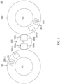
- FIG. 1A is a schematic perspective view of an injection molding system 100 in accordance with some embodiments of the present disclosure
- FIG. 1B is a schematic top view of the injection molding system 100 of FIG. 1A
- the injection molding system 100 includes a first carrier 101 and a second carrier 102 disposed adjacent to the first carrier 101.
- the first carrier 101 is rotatable about a first center C1 and along a first direction R1
- the second carrier 102 is rotatable about a second center C2 and along a second direction R2.
- the first carrier 101 and the second carrier 102 are in an annular shape.
- the first carrier 101 and the second carrier 102 are turntables.
- the first carrier 101 is rotatable in a direction same as the second carrier 102.
- both the first carrier 101 and the second carrier 102 are rotatable in anti-clockwise direction.
- the first carrier 101 is rotatable in a direction opposite to the second carrier 102.
- the first carrier 101 is rotatable in anti-clockwise direction
- the second carrier 102 is rotatable in clockwise direction, or vice versa.
- the first carrier 101 and the second carrier 102 are operated and controlled automatically.
- the first carrier 101 and the second carrier 102 communicable with each other through any suitable communication protocol such as programmable logic control (PLC) protocol or the like.
- PLC programmable logic control
- multiple molding stations 200 are configured on the first carrier 101 and the second carrier 102.
- Each molding station 200 includes a lower mold 201 and an upper mold 202 disposed above the lower mold 201.
- the molding stations 200 configured on the first carrier 101 are referred as the first molding stations 200a
- the molding stations 200 configured on the second carrier 102 are referred as the second molding stations 200b.
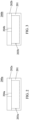
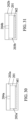
- FIG. 2 is a schematic cross-sectional view of the first molding station 200a in a closed configuration in accordance with some embodiments of the present disclosure.
- the first molding station 200a includes a lower mold 201 and a first upper mold 202a.
- the first upper mold 202a corresponds to the lower mold 201 in some configurations such as dimension, shape or the like.
- the first upper mold 202a can be placed on and engaged with the lower mold 201.
- a first mold cavity 203a is defined by the first upper mold 202a and the lower mold 201 when the first molding station 200a is in the closed configuration.
- FIG. 2 illustrates only one first mold cavity 203a in the closed configuration, it can be understood that any suitable numbers of the first mold cavity 203a can be configured in the closed configuration.
- a first sprue 204a is configured at the first upper mold 202a.
- the first sprue 204a is configured to extend through the first upper mold 202a, and is communicable with the first mold cavity 203a when the first molding station 200a is in the closed configuration.
- first sprue 204a is illustrated, however, it can be understood that any suitable numbers of the first sprue 204a can be configured at the first upper mold 202a.
- a removable plate (not shown) can be placed between the first upper mold 202a and the lower mold 201 for adjusting a volume of the first mold cavity 203a.
- the first mold cavity 203a would be reduced if the removable plate is inserted into the first mold cavity 203a and disposed between the first upper mold 202a and the lower mold 201.
- the volume of the first mold cavity 203a can be adjusted by insertion of the removable plate between the first upper mold 202a and the lower mold 201 when the first molding station 200a is closed.
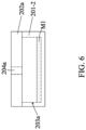
- FIG. 3 is a schematic cross-sectional view of the second molding station 200b in a closed configuration in accordance with some embodiments of the present disclosure.
- the second molding station 200b includes the lower mold 201 and a second upper mold 202b.
- the second upper mold 202b corresponds to the lower mold 201 in some configurations such as dimension, shape or the like.
- the second upper mold 202b can be placed on and engaged with the lower mold 201.
- a second mold cavity 203b is defined by the second upper mold 202b and the lower mold 201 when the second molding station 200b is in the closed configuration.
- a second sprue 204b is configured at the second upper mold 202b.
- the second sprue 204b is configured to extend through the second upper mold 202b, and is communicable with the second mold cavity 203b when the second molding station 200b is in the closed configuration.
- a removable plate (not shown) can be placed between the second upper mold 202b and the lower mold 201 for adjusting a volume of the second mold cavity 203b.
- each of the first carrier 101 and the second carrier 102 includes multiple holders (not shown) for holding the first upper molds 202a or the second upper molds 202b.
- the first upper mold 202a of FIG. 2 and the second upper mold 202b of FIG. 3 have different configurations.
- the lower molds 201 of the first molding stations 200a in FIG. 2 and the lower molds 201 of the second molding stations 200b in FIG. 3 have the same configurations.
- the injection molding system 100 further includes a first injector 104 adjacent to the first carrier 101 and a second injector 105 adjacent to the second carrier 102.
- the first injector 104 is disposed over one of the first molding stations 200a and configured to discharge a first polymeric material M1 into the first mold cavity 203a defined by the corresponding lower mold 201 and the corresponding first upper mold 202a of the one of the first molding stations 200a.
- the second injector 105 is disposed over one of the second molding stations 200b and configured to discharge a second polymeric material M2 into the second mold cavity 203b defined by the corresponding lower mold 201 and the corresponding second upper mold 202b of the one of the second molding stations 200b.
- the first polymeric material M1 can be flowed from the first injector 104 into the first mold cavity 203a through the first sprue 204a, and the second polymeric material M2 can be flowed from the second injector 105 into the second mold cavity 203b through the second sprue 204b.
- the first injector 104 is coupled to a first mixing unit (not shown) that is configured to mix a polymeric material with a blowing agent to produce the first polymeric material and convey the first polymeric material to the first injector 104.
- the second injector 105 is coupled to a second mixing unit (not shown) that is configured to mix a polymeric material with a blowing agent to produce the second polymeric material and convey the second polymeric material to the second injector 105.
- the first injector 104 is disposed over the first carrier 101. In some embodiments, the holders (not shown) pass under the first injector 104 one by one upon rotation of the first carrier 101. In some embodiments, the first injector 104 is fixedly installed over the first carrier 101. The first carrier 101 is movable relative to the first injector 104, and the first injector 104 is stationary relative to the first carrier 101.
- the second injector 105 is disposed over the second carrier 102. In some embodiments, the holders (not shown) pass under the second carrier 102 one by one upon rotation of the second carrier 102. In some embodiments, the second injector 105 is fixedly installed over the second carrier 102. The second carrier 102 is movable relative to the second injector 105, and the second injector 105 is stationary relative to the second carrier 102.
- the first polymeric material M1 and the second polymeric material M2 have the same or different physical properties (such as density, hardness, Young's modules, etc.).
- the first polymeric material M1 and the second polymeric material M2 include thermoplastic polyurethane (TPU), polyurethane (PU), plastics or any other suitable materials.
- the first polymeric material and the second polymeric material are foamable materials.
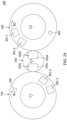
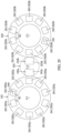
- the bridging mechanism 103 is in an annular shape. In some embodiments, the bridging mechanism 103 is rotatable about a third center C3 and along a third direction R3. In some embodiments, the bridging mechanism 103 is rotatable in clockwise or anti-clockwise. In some embodiments, the bridging mechanism 103 is removable and detachable from the injection molding system 100. The bridging mechanism 103 is operable independent from the first carrier 101 and the second carrier 102. In some embodiments, the first center C1 of the first carrier 101, the third center C3 of the bridging mechanism 103 and the second center C2 of the second carrier 102 are arranged on a straight line. In other words, the first carrier 101 and the second carrier 102 are disposed at opposite sides of the bridging mechanism 103.
- the bridging mechanism 103 includes two conveying units 103a and 103b.
- the conveying units 103a and 103b are disposed at opposite sides of the bridging mechanism 103.
- Each of the conveying units 103a and 103b is configured to convey the lower mold 201 from the first carrier 101 to the bridging mechanism 103 or vice versa, or from the second carrier 102 to the bridging mechanism 103 or vice versa.
- each of the conveying units 103a and 103b is a rail, belt or any other conveying means.
- the bridging mechanism 103 may include single or more than two conveying units.
- the bridging mechanism 103 further includes two receiving spaces 103c and 103d.
- the receiving spaces 103c and 103d are disposed at opposite sides of the bridging mechanism 103.
- Each of the receiving spaces 103c and 103d is configured to receive and temporarily hold the lower mold 201 to be conveyed.
- one lower mold 201 can be held within one of the receiving spaces 103c and 103d during the rotation of the bridging mechanism 103.
- the two lower mold 201 can be held within the receiving spaces 103c and 103d, respectively.
- the receiving space 103c and the conveying unit 103a are positioned in close proximity to each other, either set together or placed adjacent to one another, and the receiving space 103d and the conveying unit 103b are positioned in close proximity to each other.
- the injection molding system 100 further includes an additional processing unit (not shown) that is arranged adjacent to the bridging mechanism 103.
- the additional processing unit is configured to treat or process the lower mold 201 when the lower mold 201 is held within the receiving space 103c or 103d.
- the additional processing unit is configured to perform various processes such as inserting a color block into the lower mold 201, trimming a runner or other redundant part from an intermediate article inside the lower mold 201, heating or pre-heating the lower mold 201 and/or the intermediate article inside the lower mold 201, cleaning the lower mold 201, etc.
- the additional processing unit includes an injector, a cutter, a heater, a cleaner and so on.
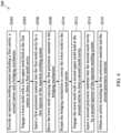
- FIG. 4 is a flowchart showing an injection molding method 300 in accordance with some embodiments of the present disclosure.
- the injection molding method 300 includes the operations S302 through S316, and the description and illustrations are not deemed as a limitation of the sequence of the operations S302 through S316.
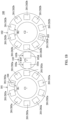
- FIGs. 5-31 are schematic top or cross-sectional views of various stages of the injection molding method 300. In some embodiments, the operations of the injection molding method 300 can be repeated and performed automatically.
- the injection molding system 100 is provided or received, as shown in FIG. 5 .
- the injection molding system 100 of FIG. 5 has same configuration as the one shown in FIGs. 1A and 1B .
- only two lower molds 201 on the first carrier 101 and two lower molds 201 on the second carrier 102 are shown in FIG. 5 .
- each of the lower molds 201 on the first carrier 101 is under the corresponding one of the first upper molds 202a
- each of the lower molds 201 on the second carrier 102 is under the corresponding one of the second upper molds 202b.
- the first injector 104 is disposed above one of the first molding stations 200a, and the second injector 105 is disposed above one of the second molding stations 200b.
- all of the first upper molds 202a are fixedly attached to the first carrier 101, and all of the second upper molds 202b are fixedly attached to the second carrier 102.
- the lower molds 201 on the first carrier 101 are referred to as a first lower mold 201-1 and a second lower mold 201-2
- the lower molds 201 on the second carrier 102 are referred to as a third lower mold 201-3 and a fourth lower mold 201-4
- the first injector 104 is disposed above the second lower mold 201-2 and the corresponding one of the first upper molds 202a
- the second injector 105 is disposed above the fourth lower mold 201-4 and the corresponding one of the second upper molds 202b.
- the lower mold on the first carrier 101 under the first injector 104 (e.g., the lower mold 201-2 of FIG. 5 ) is engaged with the corresponding one of the first upper molds 202a to form the first mold cavity 203a.
- the first polymeric material M1 is injected into the first mold cavity by the first injector 104.
- the first polymeric material M1 from the first injector 104 is injected into the first mold cavity 203a through the first sprue 204a, and the first mold cavity 203a is formed by the lower mold 201-2 under the first injector 104 and the corresponding first upper mold 202a.
- the first polymeric material M1 includes thermoplastic polyurethane (TPU), polyurethane (PU), plastics or any other suitable materials.
- the first polymeric material M1 includes a physical blowing agent such as supercritical fluid.
- the physical blowing agent is gaseous nitrogen, carbon dioxide, etc.
- the first polymeric material M1 is foamable, non-foamable or slightly foamable.
- FIG. 7 shows the first carrier 101 and the second carrier 102 after the rotation.
- the first carrier 101 and the second carrier 102 are rotated at a predetermined interval.
- the first carrier 101 and the second carrier 102 are rotated independently or simultaneously.
- the first carrier 101 and the second carrier 102 are rotated in different speed or the same speed.
- the first direction R1 and the second direction R2 can be same as or different from each other. As shown in FIG.
- the first lower mold 201-1 and the corresponding one of the first upper molds 202a are disposed adjacent to the first receiving space 103c of the bridging mechanism 103
- the third lower mold 201-3 and the corresponding one of the second upper molds 202b are disposed adjacent to the second receiving space 103d of the bridging mechanism 103.
- the first lower mold 201-1 is aligned with the first receiving space 103c
- the third lower mold 201-3 is aligned with the second receiving space 103d.
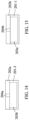
- the first lower mold 201-1 is disengaged with the corresponding one of the first upper molds 202a as shown in FIG. 8 .
- no first polymeric material M1 is injected into the first mold cavity 203a of the lower mold 201-1.
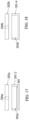
- the third lower mold 201-3 is disengaged with the corresponding one of the second upper molds 202b as shown in an open configuration of FIG. 9 . That is, the first lower mold 201-1 is movable relative to the first carrier 101, and the third lower mold 201-3 is movable relative to the second carrier 102.
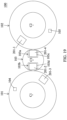
- the first lower mold 201-1 and the third lower mold 201-3 are disengaged, the first lower mold 201-1 is moved from the first carrier 101 into the first receiving space 103c of the bridging mechanism 103 by the first conveying unit 103a, and the third lower mold 201-3 is moved from the second carrier 102 into the second receiving space 103d of the bridging mechanism 103 by the second conveying unit 103b, as shown in FIG. 10 .
- the bridging mechanism 103 is rotated in the third direction R3 to convey the first lower mold 201-1 and the third lower mold 201-3.
- the first carrier 101 and the second carrier 102 stop rotation temporarily during the rotation of the bridging mechanism 103.
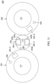
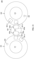
- the bridging mechanism 103 is rotated in a predetermined angle as shown in FIG. 11 so that the first lower mold 201-1 is away from the first carrier 101 and the third lower mold 201-3 is away from the second carrier 102.
- the first lower mold 201-1 and the third lower mold 201-3 are processed by one or more additional processing units (not shown) configured at or over the bridging mechanism 103.
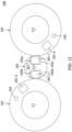
- the bridging mechanism 103 then continues the rotation, so that the first lower mold 201-1 is disposed adjacent to the second carrier 102 and the third lower mold 201-3 is disposed adjacent to the first carrier 101 as shown in FIG. 12 .
- the bridging mechanism 103 is rotated directly from a position as shown in FIG. 10 to a position as shown in FIG. 12 , without stopping at a position as shown in FIG. 11 .
- the first lower mold 201-1 is disposed adjacent to the second carrier 102
- the third lower mold 201-3 is disposed adjacent to the first carrier 101.
- the first lower mold 201-1 is moved from the bridging mechanism 103 into the second carrier 102, and the third lower mold 201-3 is moved from the bridging mechanism 103 into the first carrier 101, as shown in FIG. 13 .
- the first lower mold 201-1 is moved by the first conveying unit 103a to leave the first receiving space 103c and enter the second carrier 102
- the third lower mold 201-3 is moved by the second conveying unit 103b to leave the second receiving space 103d and enter the first carrier 101.
- the first lower mold 201-1 is conveyed from the first carrier 101 to the second carrier 102
- the third lower mold 201-3 is conveyed from the second carrier 102 to the first carrier 101.
- the bridging mechanism 103 is capable of exchanging the first lower mold 201-1 and the third lower mold 201-3 between the first carrier 101 and the second carrier 102.
- the first polymeric material M1 has been injected into the first mold cavity 203a by the first injector 104 (in the operation S306 of FIG. 4 ), and thus the first polymeric material M1 is disposed inside the disengaged second lower mold 201-2 of FIG. 17 .
- the second lower mold 201-2 carrying the first polymeric material M1 is moved from the first carrier 101 into the second receiving space 103d by the second conveying unit 103b, and the fourth lower mold 201-4 is moved from the second carrier 102 into the first receiving space 103c by the first conveying unit 103a.
- the bridging mechanism 103 is rotated in the third direction R3 to convey the second lower mold 201-2 and the fourth lower mold 201-4, as shown in FIG. 20 .
- the first carrier 101 and the second carrier 102 stop rotation temporarily during the rotation of the bridging mechanism 103.
- the second polymeric material M2 is injected from the second injector 105 into the second molding station 200b under the second injector 105 as shown in FIG. 26 .
- the second polymeric material M2 is injected into the second mold cavity 203b through the second sprue 204b.
- the second mold cavity 203b is defined by the second upper mold 202b and the corresponding lower mold 201 when the second molding station 200b is in the closed configuration.
- the second polymeric material M2 includes thermoplastic polyurethane (TPU), polyurethane (PU), plastics or any other suitable materials.
- the second polymeric material M2 includes a physical blowing agent such as supercritical fluid.
- the physical blowing agent is gaseous nitrogen, carbon dioxide, etc.
- the second polymeric material M2 is foamable, non-foamable or slightly foamable.
- the first polymeric material M1 is different from the second polymeric material M2.
- the first polymeric material M1 and the second polymeric material M2 have different materials, different physical properties, etc.
- the first polymeric material M1 and the second polymeric material M2 have different densities, hardnesses and so on.
- the second carrier 102 After injecting the second polymeric material M2 into the first mold cavity 203, the second carrier 102 is rotated in the second direction R2 such that the second lower mold 201-2 and the corresponding one of second upper molds 202b are moved away from the second injector 105. After moving the second lower mold 201-2 and the corresponding one of second upper molds 202b away from the second injector 105, the corresponding one of second upper molds 202b is disengaged with the second lower mold 201-2 so that an article M including the first polymeric material M1 and the second polymeric material M2 can be taken out from the second lower mold 201-2.
- the article M is a part of a footwear (such as outsole, insole, midsole, etc.) or any other products.
- the first carrier 101 and the second carrier 102 continue to rotate, as described above.
- the first lower mold 201-1 and the third lower mold 201-3 have been exchanged by the bridging mechanism 103, as shown in FIG. 28 .
- the first lower mold 201-1 is an empty mold from which the article M has be taken out
- the third lower mold 201-3 is the lower mold carrying the first polymeric material M1 injected by the first injector 104.
- the second lower mold 201-2 and the corresponding one of the second upper molds 202b are disposed adjacent to the first receiving space 103c of the bridging mechanism 103
- the fourth mold 201-4 and the corresponding one of the first upper molds 202a are disposed adjacent to the second receiving space 103d of the bridging mechanism 103.
- the bridging mechanism 103 (as shown in broken lines in FIG. 29 ) can be idle, stopped, in not-in-use state, or even disconnected or removed from the injection molding system 100, while the first carrier 101 and the second carrier 102 are operated individually and perform those relevant steps of the injection molding method as described above independently.
- the rotation of the first carrier 101 is independent from the rotation of the second carrier 102.
- the first upper molds 202a and the lower molds 201 on the first carrier 101 are moved by the rotation of the first carrier 101.
- the first polymeric material M1 is injected from the first injector 104 into the first mold cavity 203a through the first sprue 204a as shown in FIG. 30 .
- the first upper mold 202a and the corresponding lower mold 201 are moved away from the first injector 104 by the rotation of the first carrier 101.
- the first upper mold 202a is disengaged from the corresponding lower mold 201, so that an article having the first polymeric material M1 is formed inside the corresponding lower mold 201 and can be taken out from the corresponding lower mold 201.
- the second upper molds 202b and the lower molds 201 on the second carrier 102 are moved by the rotation of the second carrier 102.
- the second polymeric material M2 is injected from the second injector 105 into the second mold cavity 203b through the second sprue 204b as shown in FIG. 31 .
- the second upper mold 202b and the corresponding lower mold 201 are moved away from the second injector 105 by the rotation of the second carrier 102.
- the second upper mold 202b is disengaged from the corresponding lower mold 201, so that an article having the second polymeric material M2 is formed inside the corresponding lower mold 201 and can be taken out from the corresponding lower mold 201.
- the first polymeric material M1 and the second polymeric material M2 are same or different materials. In some embodiments, the first polymeric material M1 and the second polymeric material M2 have same or different physical properties.
- the injection molding system 100 is controlled by a controller (not shown).
- the controller is configured to control the rotation of the first carrier 101, the rotation of the second carrier 102, and the rotation of the bridging mechanism 103, e.g., the direction, angle and speed during the rotation, so as to form an article including more than one portion having different physical or functional properties.
- the controller is configured to idle or stop the bridging mechanism 103, so as to form an article including single physical or functional property.
- the bridging mechanism 103 is used to convey the lower molds between the first carrier 101 and the second carrier 102 by rotation or movement of the bridging mechanism 103. Through the bridging mechanism 103, the two different injections of the first injector 104 and the second injector 105 are performed continuously on the first carrier 101 and the second carrier 102, thereby decreasing manufacturing time of the article including more than one portion having different physical or functional properties.
Landscapes
- Engineering & Computer Science (AREA)
- Mechanical Engineering (AREA)
- Manufacturing & Machinery (AREA)
- Robotics (AREA)
- Injection Moulding Of Plastics Or The Like (AREA)
- Molding Of Porous Articles (AREA)
- Moulds For Moulding Plastics Or The Like (AREA)
Claims (15)
- Ein Spritzgussverfahren (100), das Folgendes umfasst:einen ersten Träger (101), der so konfiguriert ist, dass er eine erste Gussform hält;eine erste Injektor (104), die über dem ersten Träger angeordnet und so konfiguriert ist, dass sie ein erstes Polymermaterial einspritzt;einen zweiten Träger (102), der so konfiguriert ist, dass er eine zweite Gussform hält;eine zweite Injektor (105), die über dem zweiten Träger angeordnet ist und so konfiguriert ist, dass sie ein zweites Polymermaterial einspritzt; dadurch gekennzeichnet, dass sie fernereinen Überbrückungsmechanismus (103) umfasst, der zwischen dem ersten Träger und dem zweiten Träger angeordnet und relativ zu diesen beweglich ist und so konfiguriert ist, dass er eine dritte Gussform von dem ersten Träger oder dem zweiten Träger aufnimmt und die dritte Gussform zwischen dem ersten Träger und dem zweiten Träger befördert.
- Das Spritzgussverfahren nach Anspruch 1, wobei das erste und das zweite polymere Material schäumbare, nicht schäumbare oder leicht schäumbare Materialien sind.
- Das Spritzgussverfahren nach Anspruch 1 oder 2, wobei die neben der ersten Gussform angeordnete dritte Gussform von dem ersten Träger zu dem zweiten Träger befördert werden kann, um die dritte Gussform neben der zweiten Gussform anzuordnen, oder die neben der zweiten Gussform angeordnete dritte Gussform von dem zweiten Träger zu dem ersten Träger befördert werden kann, um die dritte Gussform neben der ersten Gussform anzuordnen.
- Das Spritzgussverfahren nach einem der Ansprüche 1 bis 3, wobei ein erster Hohlraum der Gussform (203a) durch die erste Gussform und die dritte Gussform definiert ist und einen zweiten Hohlraum der Gussform (203b) durch die zweite Gussform und die dritte Gussform definiert ist, wobei das erste polymere Material in den ersten Hohlraum der Gussform durch die erste Injektor eingespritzt wird und das zweite polymere Material in den zweiten Hohlraum der Gussform durch die zweite Injektor eingespritzt wird.
- Das Spritzgussverfahren nach Anspruch 4, wobei die erste Gussform einen ersten Einguss (204a) umfasst, der so konfiguriert ist, dass er das erste polymere Material aus der ersten Injektor aufnimmt und mit dem ersten Hohlraum des Gussform in Verbindung steht, und die zweite Gussform einen zweiten Einguss (204b) umfasst, der so konfiguriert ist, dass er das zweite polymere Material aus der zweiten Injektor aufnimmt und mit dem zweiten Hohlraum der Gussform in Verbindung steht.
- Das Spritzgussverfahren nach einem der Ansprüche 1 bis 5, wobei der Überbrückungsmechanismus Folgendes umfasst:eine erste Fördereinheit (103a), die so konfiguriert ist, dass sie die dritte Gussform von dem ersten Träger zu einem ersten Aufnahmebereich (103c) des Überbrückungsmechanismus befördert; undeine zweite Fördereinheit (103b), die so konfiguriert ist, dass sie die dritte Gussform von dem zweiten Träger zu einem zweiten Aufnahmebereich (103d) des Überbrückungsmechanismus fördert.
- Das Spritzgussverfahren nach Anspruch 6, wobei der erste und der zweite Aufnahmebereich auf gegenüberliegenden Seiten des Überbrückungsmechanismus angeordnet sind.
- Das Spritzgussverfahren nach einem der Ansprüche 1 bis 7, wobei der erste und der zweite Träger relativ zum Überbrückungsmechanismus drehbar sind.
- Ein Spritzgussverfahren, das Folgendes umfasst:das Bereitstellen eines Spritzgussverfahrens mit einem ersten Träger, einem zweiten Träger, der neben dem ersten Träger angeordnet ist, einem Überbrückungsmechanismus zwischen dem ersten Träger und dem zweiten Träger, einer ersten Injektor über dem ersten Träger, einer zweiten Injektor über dem zweiten Träger, einer ersten Gussform, die auf dem ersten Träger gehalten wird, und einer zweiten Gussform, die auf dem zweiten Träger gehalten wird;das Ineinandergreifen einer dritten Gussform mit der ersten Gussform, um einen ersten Hohlraum einer Gussform zu bilden;das Einspritzen eines ersten Polymermaterials in den ersten Hohlraum der Gussform durch die erste Injektor;das Bewegen der dritten Gussform, die das erste Polymermaterial trägt, zu dem Überbrückungsmechanismus;das Befördern der dritten Gussform zu dem zweiten Träger durch den Überbrückungsmechanismus;das Ineinandergreifen der dritten Gussform mit der zweiten Gussform, um einen zweiten Hohlraum der Gussform zu bilden;das Einspritzen eines zweiten Polymermaterials in den zweiten Hohlraum der Gussform durch die zweite Injektor; unddas Erhalten eines Artikels, der das erste polymere Material und das zweite polymere Material enthält.
- Das Spritzgussverfahren nach Anspruch 9, das außerdem Folgendes umfasst:nach dem Einspritzen des ersten Polymermaterials, das Lösen der dritten Gussform von der ersten Gussform; undnach dem Einspritzen des zweiten Polymermaterials das, Lösen der dritten Gussform von der zweiten Gussform.
- Das Spritzgussverfahren nach Anspruch 9 oder 10, das außerdem Folgendes umfasst:das Bereitstellen einer vierten Gussform auf dem zweiten Träger;das Bewegen der vierten Gussform zu dem Überbrückungsmechanismus; unddas Befördern der vierten Gussform zu dem ersten Träger durch den Überbrückungsmechanismus.
- Das Spritzgussverfahren nach Anspruch 11, wobei das Bewegen der vierten Gussform und das Bewegen der dritten Gussform gleichzeitig durchgeführt werden und die vierte Gussform von dem zweiten Träger zu dem ersten Träger befördert wird, wenn die dritte Gussform von dem ersten Träger zu dem zweiten Träger befördert wird.
- Das Spritzgussverfahren nach einem der Ansprüche 9 bis 12, das außerdem Folgendes umfasst:
das Anhalten der Drehungen des ersten und zweiten Trägers beim Bewegen der dritten Gussform zum Überbrückungsmechanismus. - Das Spritzgussverfahren nach einem der Ansprüche 9 bis 12, das außerdem Folgendes umfasst:das Bewegen der dritten Gussform vom zweiten Träger zum Überbrückungsmechanismus,wobei der erste Träger und der zweite Träger die Drehungen beim Bewegen der dritten Gussform vom zweiten Träger zum Überbrückungsmechanismus anhalten.
- Das Spritzgussverfahren nach einem der Ansprüche 9 bis 14, das außerdem Folgendes umfasst:
das Bewegen der dritten Gussform vom zweiten Träger zum Überbrückungsmechanismus, nachdem der Artikel erhalten wurde.
Applications Claiming Priority (2)
| Application Number | Priority Date | Filing Date | Title |
|---|---|---|---|
| US202363491529P | 2023-03-21 | 2023-03-21 | |
| US18/542,758 US20240316841A1 (en) | 2023-03-21 | 2023-12-17 | Injection molding system and method |
Publications (2)
| Publication Number | Publication Date |
|---|---|
| EP4434714A1 EP4434714A1 (de) | 2024-09-25 |
| EP4434714B1 true EP4434714B1 (de) | 2025-05-21 |
Family
ID=90365116
Family Applications (1)
| Application Number | Title | Priority Date | Filing Date |
|---|---|---|---|
| EP24163187.8A Active EP4434714B1 (de) | 2023-03-21 | 2024-03-13 | Spritzgiesssystem und verfahren |
Country Status (6)
| Country | Link |
|---|---|
| US (1) | US20240316841A1 (de) |
| EP (1) | EP4434714B1 (de) |
| JP (1) | JP7758380B2 (de) |
| KR (1) | KR20240142286A (de) |
| CN (1) | CN222741952U (de) |
| TW (2) | TWM657189U (de) |
Families Citing this family (1)
| Publication number | Priority date | Publication date | Assignee | Title |
|---|---|---|---|---|
| US20240316841A1 (en) * | 2023-03-21 | 2024-09-26 | King Steel Machinery Co., Ltd. | Injection molding system and method |
Family Cites Families (14)
| Publication number | Priority date | Publication date | Assignee | Title |
|---|---|---|---|---|
| JP3219643B2 (ja) * | 1994-11-18 | 2001-10-15 | 三菱重工業株式会社 | タイヤ金型運搬装置 |
| US6719551B2 (en) * | 1997-12-18 | 2004-04-13 | Dale E. Polk, Jr. | Thermoplastic molding process and apparatus |
| US6709251B2 (en) * | 2001-11-16 | 2004-03-23 | Mgs Enterprises, Inc. | Self-contained frameless rotating mold support |
| DE102004062510A1 (de) * | 2004-12-24 | 2006-07-06 | Bayer Materialscience Ag | Verfahren zum Formen und Beschichten eines Substrats |
| DE102006010310A1 (de) | 2006-03-07 | 2007-09-13 | Krauss-Maffei Kunststofftechnik Gmbh | Vorrichtung und Verfahren zur Herstellung von Mehrkomponenten-Kunststoffteilen |
| DE102006016200A1 (de) | 2006-04-06 | 2007-10-11 | Krauss-Maffei Kunststofftechnik Gmbh | Verfahren und Vorrichtung zur Herstellung von mehrkomponentigen Kunststoff-Formteilen |
| TWI398339B (zh) * | 2010-09-17 | 2013-06-11 | Pegatron Corp | 模具傳遞裝置及模具系統 |
| JP5559278B2 (ja) * | 2012-09-19 | 2014-07-23 | ファナック株式会社 | 多色成形品の製造方法および射出成形システム |
| US20210394408A1 (en) * | 2018-11-14 | 2021-12-23 | Mitsuba Corporation | Apparatus and method for manufacturing injection molded article, and resin molded article |
| JP7360870B2 (ja) | 2019-09-24 | 2023-10-13 | 東洋機械金属株式会社 | 射出成形機 |
| US12049032B2 (en) * | 2020-03-20 | 2024-07-30 | King Steel Machinery Co., Ltd. | Injection molding method |
| US12186954B2 (en) * | 2020-06-24 | 2025-01-07 | King Steel Machinery Co., Ltd. | Injection molding system having movable molding device and method thereof |
| CN114347358B (zh) * | 2021-12-03 | 2023-09-26 | 广东格林精密部件股份有限公司 | 一种壁厚均匀的中空塑胶件的制造设备及其成型方法 |
| US20240316841A1 (en) * | 2023-03-21 | 2024-09-26 | King Steel Machinery Co., Ltd. | Injection molding system and method |
-
2023
- 2023-12-17 US US18/542,758 patent/US20240316841A1/en active Pending
-
2024
- 2024-02-21 JP JP2024024814A patent/JP7758380B2/ja active Active
- 2024-02-29 KR KR1020240029374A patent/KR20240142286A/ko active Pending
- 2024-03-13 CN CN202420487237.6U patent/CN222741952U/zh active Active
- 2024-03-13 TW TW113202542U patent/TWM657189U/zh unknown
- 2024-03-13 TW TW113109328A patent/TWI899888B/zh active
- 2024-03-13 EP EP24163187.8A patent/EP4434714B1/de active Active
Also Published As
| Publication number | Publication date |
|---|---|
| KR20240142286A (ko) | 2024-09-30 |
| JP7758380B2 (ja) | 2025-10-22 |
| US20240316841A1 (en) | 2024-09-26 |
| EP4434714A1 (de) | 2024-09-25 |
| TWM657189U (zh) | 2024-06-21 |
| JP2024137746A (ja) | 2024-10-07 |
| CN222741952U (zh) | 2025-04-11 |
| TWI899888B (zh) | 2025-10-01 |
| TW202438288A (zh) | 2024-10-01 |
Similar Documents
| Publication | Publication Date | Title |
|---|---|---|
| US12049032B2 (en) | Injection molding method | |
| KR102407710B1 (ko) | 사출 성형 시스템 및 사출 성형 방법 | |
| CA2643490A1 (en) | Device and method for producing multicomponent plastic parts | |
| EP4434714B1 (de) | Spritzgiesssystem und verfahren | |
| US12358189B2 (en) | Article and method of manufacturing the same | |
| US20250196458A1 (en) | Injection molding system and method | |
| US20250108541A1 (en) | Article and method of manufacturing the same | |
| US20030085483A1 (en) | Apparatus and method for making molded foam articles | |
| CN223864173U (zh) | 射出成型系统 | |
| US20240335985A1 (en) | Molding device and molding method | |
| CN118682967A (zh) | 射出成型系统及方法 | |
| US12485595B2 (en) | Injection molding system and injection molding method | |
| EP4140687A1 (de) | Artikel und verfahren zum herstellen davon | |
| EP4530044A1 (de) | Spritzgiesssystem und verfahren | |
| US20240359374A1 (en) | Molding device, injection molding system and molding method | |
| KR20180034995A (ko) | 사출 성형용 발포 성형장치 및 이를 이용한 발포 성형방법 | |
| EP4674586A1 (de) | Spritzgiessverfahren | |
| KR102843788B1 (ko) | 성형품 및 그 제조 방법 |
Legal Events
| Date | Code | Title | Description |
|---|---|---|---|
| PUAI | Public reference made under article 153(3) epc to a published international application that has entered the european phase |
Free format text: ORIGINAL CODE: 0009012 |
|
| STAA | Information on the status of an ep patent application or granted ep patent |
Free format text: STATUS: THE APPLICATION HAS BEEN PUBLISHED |
|
| AK | Designated contracting states |
Kind code of ref document: A1 Designated state(s): AL AT BE BG CH CY CZ DE DK EE ES FI FR GB GR HR HU IE IS IT LI LT LU LV MC ME MK MT NL NO PL PT RO RS SE SI SK SM TR |
|
| STAA | Information on the status of an ep patent application or granted ep patent |
Free format text: STATUS: REQUEST FOR EXAMINATION WAS MADE |
|
| 17P | Request for examination filed |
Effective date: 20241028 |
|
| RBV | Designated contracting states (corrected) |
Designated state(s): AL AT BE BG CH CY CZ DE DK EE ES FI FR GB GR HR HU IE IS IT LI LT LU LV MC ME MK MT NL NO PL PT RO RS SE SI SK SM TR |
|
| GRAP | Despatch of communication of intention to grant a patent |
Free format text: ORIGINAL CODE: EPIDOSNIGR1 |
|
| STAA | Information on the status of an ep patent application or granted ep patent |
Free format text: STATUS: GRANT OF PATENT IS INTENDED |
|
| INTG | Intention to grant announced |
Effective date: 20250304 |
|
| GRAS | Grant fee paid |
Free format text: ORIGINAL CODE: EPIDOSNIGR3 |
|
| GRAA | (expected) grant |
Free format text: ORIGINAL CODE: 0009210 |
|
| STAA | Information on the status of an ep patent application or granted ep patent |
Free format text: STATUS: THE PATENT HAS BEEN GRANTED |
|
| P01 | Opt-out of the competence of the unified patent court (upc) registered |
Free format text: CASE NUMBER: APP_13499/2025 Effective date: 20250319 |
|
| AK | Designated contracting states |
Kind code of ref document: B1 Designated state(s): AL AT BE BG CH CY CZ DE DK EE ES FI FR GB GR HR HU IE IS IT LI LT LU LV MC ME MK MT NL NO PL PT RO RS SE SI SK SM TR |
|
| REG | Reference to a national code |
Ref country code: GB Ref legal event code: FG4D |
|
| REG | Reference to a national code |
Ref country code: CH Ref legal event code: EP |
|
| REG | Reference to a national code |
Ref country code: DE Ref legal event code: R096 Ref document number: 602024000138 Country of ref document: DE |
|
| REG | Reference to a national code |
Ref country code: IE Ref legal event code: FG4D |
|
| REG | Reference to a national code |
Ref country code: NL Ref legal event code: MP Effective date: 20250521 |
|
| PG25 | Lapsed in a contracting state [announced via postgrant information from national office to epo] |
Ref country code: PT Free format text: LAPSE BECAUSE OF FAILURE TO SUBMIT A TRANSLATION OF THE DESCRIPTION OR TO PAY THE FEE WITHIN THE PRESCRIBED TIME-LIMIT Effective date: 20250922 Ref country code: FI Free format text: LAPSE BECAUSE OF FAILURE TO SUBMIT A TRANSLATION OF THE DESCRIPTION OR TO PAY THE FEE WITHIN THE PRESCRIBED TIME-LIMIT Effective date: 20250521 Ref country code: ES Free format text: LAPSE BECAUSE OF FAILURE TO SUBMIT A TRANSLATION OF THE DESCRIPTION OR TO PAY THE FEE WITHIN THE PRESCRIBED TIME-LIMIT Effective date: 20250521 |
|
| REG | Reference to a national code |
Ref country code: LT Ref legal event code: MG9D |
|
| PG25 | Lapsed in a contracting state [announced via postgrant information from national office to epo] |
Ref country code: NO Free format text: LAPSE BECAUSE OF FAILURE TO SUBMIT A TRANSLATION OF THE DESCRIPTION OR TO PAY THE FEE WITHIN THE PRESCRIBED TIME-LIMIT Effective date: 20250821 Ref country code: GR Free format text: LAPSE BECAUSE OF FAILURE TO SUBMIT A TRANSLATION OF THE DESCRIPTION OR TO PAY THE FEE WITHIN THE PRESCRIBED TIME-LIMIT Effective date: 20250822 |
|
| PG25 | Lapsed in a contracting state [announced via postgrant information from national office to epo] |
Ref country code: PL Free format text: LAPSE BECAUSE OF FAILURE TO SUBMIT A TRANSLATION OF THE DESCRIPTION OR TO PAY THE FEE WITHIN THE PRESCRIBED TIME-LIMIT Effective date: 20250521 Ref country code: NL Free format text: LAPSE BECAUSE OF FAILURE TO SUBMIT A TRANSLATION OF THE DESCRIPTION OR TO PAY THE FEE WITHIN THE PRESCRIBED TIME-LIMIT Effective date: 20250521 |
|
| PG25 | Lapsed in a contracting state [announced via postgrant information from national office to epo] |
Ref country code: BG Free format text: LAPSE BECAUSE OF FAILURE TO SUBMIT A TRANSLATION OF THE DESCRIPTION OR TO PAY THE FEE WITHIN THE PRESCRIBED TIME-LIMIT Effective date: 20250521 |
|
| PG25 | Lapsed in a contracting state [announced via postgrant information from national office to epo] |
Ref country code: HR Free format text: LAPSE BECAUSE OF FAILURE TO SUBMIT A TRANSLATION OF THE DESCRIPTION OR TO PAY THE FEE WITHIN THE PRESCRIBED TIME-LIMIT Effective date: 20250521 |
|
| PG25 | Lapsed in a contracting state [announced via postgrant information from national office to epo] |
Ref country code: RS Free format text: LAPSE BECAUSE OF FAILURE TO SUBMIT A TRANSLATION OF THE DESCRIPTION OR TO PAY THE FEE WITHIN THE PRESCRIBED TIME-LIMIT Effective date: 20250821 |
|
| PG25 | Lapsed in a contracting state [announced via postgrant information from national office to epo] |
Ref country code: IS Free format text: LAPSE BECAUSE OF FAILURE TO SUBMIT A TRANSLATION OF THE DESCRIPTION OR TO PAY THE FEE WITHIN THE PRESCRIBED TIME-LIMIT Effective date: 20250921 |
|
| PG25 | Lapsed in a contracting state [announced via postgrant information from national office to epo] |
Ref country code: LV Free format text: LAPSE BECAUSE OF FAILURE TO SUBMIT A TRANSLATION OF THE DESCRIPTION OR TO PAY THE FEE WITHIN THE PRESCRIBED TIME-LIMIT Effective date: 20250521 |
|
| REG | Reference to a national code |
Ref country code: AT Ref legal event code: MK05 Ref document number: 1796406 Country of ref document: AT Kind code of ref document: T Effective date: 20250521 |
|
| PG25 | Lapsed in a contracting state [announced via postgrant information from national office to epo] |
Ref country code: SM Free format text: LAPSE BECAUSE OF FAILURE TO SUBMIT A TRANSLATION OF THE DESCRIPTION OR TO PAY THE FEE WITHIN THE PRESCRIBED TIME-LIMIT Effective date: 20250521 Ref country code: DK Free format text: LAPSE BECAUSE OF FAILURE TO SUBMIT A TRANSLATION OF THE DESCRIPTION OR TO PAY THE FEE WITHIN THE PRESCRIBED TIME-LIMIT Effective date: 20250521 Ref country code: AT Free format text: LAPSE BECAUSE OF FAILURE TO SUBMIT A TRANSLATION OF THE DESCRIPTION OR TO PAY THE FEE WITHIN THE PRESCRIBED TIME-LIMIT Effective date: 20250521 |
|
| PG25 | Lapsed in a contracting state [announced via postgrant information from national office to epo] |
Ref country code: CZ Free format text: LAPSE BECAUSE OF FAILURE TO SUBMIT A TRANSLATION OF THE DESCRIPTION OR TO PAY THE FEE WITHIN THE PRESCRIBED TIME-LIMIT Effective date: 20250521 |
|
| PG25 | Lapsed in a contracting state [announced via postgrant information from national office to epo] |
Ref country code: EE Free format text: LAPSE BECAUSE OF FAILURE TO SUBMIT A TRANSLATION OF THE DESCRIPTION OR TO PAY THE FEE WITHIN THE PRESCRIBED TIME-LIMIT Effective date: 20250521 |
|
| PG25 | Lapsed in a contracting state [announced via postgrant information from national office to epo] |
Ref country code: SK Free format text: LAPSE BECAUSE OF FAILURE TO SUBMIT A TRANSLATION OF THE DESCRIPTION OR TO PAY THE FEE WITHIN THE PRESCRIBED TIME-LIMIT Effective date: 20250521 |
|
| REG | Reference to a national code |
Ref country code: DE Ref legal event code: R097 Ref document number: 602024000138 Country of ref document: DE |
|
| PLBE | No opposition filed within time limit |
Free format text: ORIGINAL CODE: 0009261 |
|
| STAA | Information on the status of an ep patent application or granted ep patent |
Free format text: STATUS: NO OPPOSITION FILED WITHIN TIME LIMIT |
|
| REG | Reference to a national code |
Ref country code: CH Ref legal event code: L10 Free format text: ST27 STATUS EVENT CODE: U-0-0-L10-L00 (AS PROVIDED BY THE NATIONAL OFFICE) Effective date: 20260402 |
|
| PGFP | Annual fee paid to national office [announced via postgrant information from national office to epo] |
Ref country code: DE Payment date: 20260128 Year of fee payment: 3 |
|
| 26N | No opposition filed |
Effective date: 20260224 |