EP4434716A1 - Kunststoffrohr und vorrichtung zur kontinuierlichen herstellung eines rohrgrundkörpers für ein derartiges kunststoffrohr - Google Patents
Kunststoffrohr und vorrichtung zur kontinuierlichen herstellung eines rohrgrundkörpers für ein derartiges kunststoffrohr Download PDFInfo
- Publication number
- EP4434716A1 EP4434716A1 EP23163153.2A EP23163153A EP4434716A1 EP 4434716 A1 EP4434716 A1 EP 4434716A1 EP 23163153 A EP23163153 A EP 23163153A EP 4434716 A1 EP4434716 A1 EP 4434716A1
- Authority
- EP
- European Patent Office
- Prior art keywords
- pipe
- longitudinal axis
- plastic pipe
- plastic
- guide element
- Prior art date
- Legal status (The legal status is an assumption and is not a legal conclusion. Google has not performed a legal analysis and makes no representation as to the accuracy of the status listed.)
- Granted
Links
Images



Classifications
-
- F—MECHANICAL ENGINEERING; LIGHTING; HEATING; WEAPONS; BLASTING
- F16—ENGINEERING ELEMENTS AND UNITS; GENERAL MEASURES FOR PRODUCING AND MAINTAINING EFFECTIVE FUNCTIONING OF MACHINES OR INSTALLATIONS; THERMAL INSULATION IN GENERAL
- F16L—PIPES; JOINTS OR FITTINGS FOR PIPES; SUPPORTS FOR PIPES, CABLES OR PROTECTIVE TUBING; MEANS FOR THERMAL INSULATION IN GENERAL
- F16L9/00—Rigid pipes
- F16L9/18—Double-walled pipes; Multi-channel pipes or pipe assemblies
- F16L9/19—Multi-channel pipes or pipe assemblies
-
- B—PERFORMING OPERATIONS; TRANSPORTING
- B29—WORKING OF PLASTICS; WORKING OF SUBSTANCES IN A PLASTIC STATE IN GENERAL
- B29C—SHAPING OR JOINING OF PLASTICS; SHAPING OF MATERIAL IN A PLASTIC STATE, NOT OTHERWISE PROVIDED FOR; AFTER-TREATMENT OF THE SHAPED PRODUCTS, e.g. REPAIRING
- B29C48/00—Extrusion moulding, i.e. expressing the moulding material through a die or nozzle which imparts the desired form; Apparatus therefor
- B29C48/03—Extrusion moulding, i.e. expressing the moulding material through a die or nozzle which imparts the desired form; Apparatus therefor characterised by the shape of the extruded material at extrusion
- B29C48/09—Articles with cross-sections having partially or fully enclosed cavities, e.g. pipes or channels
-
- B—PERFORMING OPERATIONS; TRANSPORTING
- B29—WORKING OF PLASTICS; WORKING OF SUBSTANCES IN A PLASTIC STATE IN GENERAL
- B29C—SHAPING OR JOINING OF PLASTICS; SHAPING OF MATERIAL IN A PLASTIC STATE, NOT OTHERWISE PROVIDED FOR; AFTER-TREATMENT OF THE SHAPED PRODUCTS, e.g. REPAIRING
- B29C48/00—Extrusion moulding, i.e. expressing the moulding material through a die or nozzle which imparts the desired form; Apparatus therefor
- B29C48/03—Extrusion moulding, i.e. expressing the moulding material through a die or nozzle which imparts the desired form; Apparatus therefor characterised by the shape of the extruded material at extrusion
- B29C48/09—Articles with cross-sections having partially or fully enclosed cavities, e.g. pipes or channels
- B29C48/11—Articles with cross-sections having partially or fully enclosed cavities, e.g. pipes or channels comprising two or more partially or fully enclosed cavities, e.g. honeycomb-shaped
-
- B—PERFORMING OPERATIONS; TRANSPORTING
- B29—WORKING OF PLASTICS; WORKING OF SUBSTANCES IN A PLASTIC STATE IN GENERAL
- B29C—SHAPING OR JOINING OF PLASTICS; SHAPING OF MATERIAL IN A PLASTIC STATE, NOT OTHERWISE PROVIDED FOR; AFTER-TREATMENT OF THE SHAPED PRODUCTS, e.g. REPAIRING
- B29C48/00—Extrusion moulding, i.e. expressing the moulding material through a die or nozzle which imparts the desired form; Apparatus therefor
- B29C48/03—Extrusion moulding, i.e. expressing the moulding material through a die or nozzle which imparts the desired form; Apparatus therefor characterised by the shape of the extruded material at extrusion
- B29C48/13—Articles with a cross-section varying in the longitudinal direction, e.g. corrugated pipes
-
- B—PERFORMING OPERATIONS; TRANSPORTING
- B29—WORKING OF PLASTICS; WORKING OF SUBSTANCES IN A PLASTIC STATE IN GENERAL
- B29C—SHAPING OR JOINING OF PLASTICS; SHAPING OF MATERIAL IN A PLASTIC STATE, NOT OTHERWISE PROVIDED FOR; AFTER-TREATMENT OF THE SHAPED PRODUCTS, e.g. REPAIRING
- B29C48/00—Extrusion moulding, i.e. expressing the moulding material through a die or nozzle which imparts the desired form; Apparatus therefor
- B29C48/16—Articles comprising two or more components, e.g. co-extruded layers
- B29C48/18—Articles comprising two or more components, e.g. co-extruded layers the components being layers
- B29C48/21—Articles comprising two or more components, e.g. co-extruded layers the components being layers the layers being joined at their surfaces
-
- B—PERFORMING OPERATIONS; TRANSPORTING
- B29—WORKING OF PLASTICS; WORKING OF SUBSTANCES IN A PLASTIC STATE IN GENERAL
- B29C—SHAPING OR JOINING OF PLASTICS; SHAPING OF MATERIAL IN A PLASTIC STATE, NOT OTHERWISE PROVIDED FOR; AFTER-TREATMENT OF THE SHAPED PRODUCTS, e.g. REPAIRING
- B29C48/00—Extrusion moulding, i.e. expressing the moulding material through a die or nozzle which imparts the desired form; Apparatus therefor
- B29C48/25—Component parts, details or accessories; Auxiliary operations
- B29C48/30—Extrusion nozzles or dies
- B29C48/303—Extrusion nozzles or dies using dies or die parts movable in a closed circuit, e.g. mounted on movable endless support
-
- B—PERFORMING OPERATIONS; TRANSPORTING
- B29—WORKING OF PLASTICS; WORKING OF SUBSTANCES IN A PLASTIC STATE IN GENERAL
- B29C—SHAPING OR JOINING OF PLASTICS; SHAPING OF MATERIAL IN A PLASTIC STATE, NOT OTHERWISE PROVIDED FOR; AFTER-TREATMENT OF THE SHAPED PRODUCTS, e.g. REPAIRING
- B29C48/00—Extrusion moulding, i.e. expressing the moulding material through a die or nozzle which imparts the desired form; Apparatus therefor
- B29C48/25—Component parts, details or accessories; Auxiliary operations
- B29C48/30—Extrusion nozzles or dies
- B29C48/32—Extrusion nozzles or dies with annular openings, e.g. for forming tubular articles
-
- B—PERFORMING OPERATIONS; TRANSPORTING
- B29—WORKING OF PLASTICS; WORKING OF SUBSTANCES IN A PLASTIC STATE IN GENERAL
- B29C—SHAPING OR JOINING OF PLASTICS; SHAPING OF MATERIAL IN A PLASTIC STATE, NOT OTHERWISE PROVIDED FOR; AFTER-TREATMENT OF THE SHAPED PRODUCTS, e.g. REPAIRING
- B29C48/00—Extrusion moulding, i.e. expressing the moulding material through a die or nozzle which imparts the desired form; Apparatus therefor
- B29C48/25—Component parts, details or accessories; Auxiliary operations
- B29C48/30—Extrusion nozzles or dies
- B29C48/32—Extrusion nozzles or dies with annular openings, e.g. for forming tubular articles
- B29C48/335—Multiple annular extrusion nozzles in coaxial arrangement, e.g. for making multi-layered tubular articles
-
- B—PERFORMING OPERATIONS; TRANSPORTING
- B29—WORKING OF PLASTICS; WORKING OF SUBSTANCES IN A PLASTIC STATE IN GENERAL
- B29C—SHAPING OR JOINING OF PLASTICS; SHAPING OF MATERIAL IN A PLASTIC STATE, NOT OTHERWISE PROVIDED FOR; AFTER-TREATMENT OF THE SHAPED PRODUCTS, e.g. REPAIRING
- B29C48/00—Extrusion moulding, i.e. expressing the moulding material through a die or nozzle which imparts the desired form; Apparatus therefor
- B29C48/25—Component parts, details or accessories; Auxiliary operations
- B29C48/88—Thermal treatment of the stream of extruded material, e.g. cooling
- B29C48/885—External treatment, e.g. by using air rings for cooling tubular films
-
- B—PERFORMING OPERATIONS; TRANSPORTING
- B29—WORKING OF PLASTICS; WORKING OF SUBSTANCES IN A PLASTIC STATE IN GENERAL
- B29C—SHAPING OR JOINING OF PLASTICS; SHAPING OF MATERIAL IN A PLASTIC STATE, NOT OTHERWISE PROVIDED FOR; AFTER-TREATMENT OF THE SHAPED PRODUCTS, e.g. REPAIRING
- B29C48/00—Extrusion moulding, i.e. expressing the moulding material through a die or nozzle which imparts the desired form; Apparatus therefor
- B29C48/25—Component parts, details or accessories; Auxiliary operations
- B29C48/88—Thermal treatment of the stream of extruded material, e.g. cooling
- B29C48/911—Cooling
- B29C48/9115—Cooling of hollow articles
- B29C48/912—Cooling of hollow articles of tubular films
-
- F—MECHANICAL ENGINEERING; LIGHTING; HEATING; WEAPONS; BLASTING
- F16—ENGINEERING ELEMENTS AND UNITS; GENERAL MEASURES FOR PRODUCING AND MAINTAINING EFFECTIVE FUNCTIONING OF MACHINES OR INSTALLATIONS; THERMAL INSULATION IN GENERAL
- F16L—PIPES; JOINTS OR FITTINGS FOR PIPES; SUPPORTS FOR PIPES, CABLES OR PROTECTIVE TUBING; MEANS FOR THERMAL INSULATION IN GENERAL
- F16L11/00—Hoses, i.e. flexible pipes
- F16L11/04—Hoses, i.e. flexible pipes made of rubber or flexible plastics
- F16L11/11—Hoses, i.e. flexible pipes made of rubber or flexible plastics with corrugated wall
- F16L11/118—Hoses, i.e. flexible pipes made of rubber or flexible plastics with corrugated wall having arrangements for particular purposes, e.g. electrically conducting
-
- F—MECHANICAL ENGINEERING; LIGHTING; HEATING; WEAPONS; BLASTING
- F16—ENGINEERING ELEMENTS AND UNITS; GENERAL MEASURES FOR PRODUCING AND MAINTAINING EFFECTIVE FUNCTIONING OF MACHINES OR INSTALLATIONS; THERMAL INSULATION IN GENERAL
- F16L—PIPES; JOINTS OR FITTINGS FOR PIPES; SUPPORTS FOR PIPES, CABLES OR PROTECTIVE TUBING; MEANS FOR THERMAL INSULATION IN GENERAL
- F16L11/00—Hoses, i.e. flexible pipes
- F16L11/22—Multi-channel hoses
-
- H—ELECTRICITY
- H02—GENERATION; CONVERSION OR DISTRIBUTION OF ELECTRIC POWER
- H02G—INSTALLATION OF ELECTRIC CABLES OR LINES, OR OF COMBINED OPTICAL AND ELECTRIC CABLES OR LINES
- H02G3/00—Installations of electric cables or lines or protective tubing therefor in or on buildings, equivalent structures or vehicles
- H02G3/02—Details
- H02G3/04—Protective tubing or conduits, e.g. cable ladders or cable troughs
- H02G3/0462—Tubings, i.e. having a closed section
- H02G3/0468—Corrugated
-
- H—ELECTRICITY
- H02—GENERATION; CONVERSION OR DISTRIBUTION OF ELECTRIC POWER
- H02G—INSTALLATION OF ELECTRIC CABLES OR LINES, OR OF COMBINED OPTICAL AND ELECTRIC CABLES OR LINES
- H02G3/00—Installations of electric cables or lines or protective tubing therefor in or on buildings, equivalent structures or vehicles
- H02G3/02—Details
- H02G3/04—Protective tubing or conduits, e.g. cable ladders or cable troughs
- H02G3/0462—Tubings, i.e. having a closed section
- H02G3/0481—Tubings, i.e. having a closed section with a circular cross-section
-
- B—PERFORMING OPERATIONS; TRANSPORTING
- B29—WORKING OF PLASTICS; WORKING OF SUBSTANCES IN A PLASTIC STATE IN GENERAL
- B29C—SHAPING OR JOINING OF PLASTICS; SHAPING OF MATERIAL IN A PLASTIC STATE, NOT OTHERWISE PROVIDED FOR; AFTER-TREATMENT OF THE SHAPED PRODUCTS, e.g. REPAIRING
- B29C48/00—Extrusion moulding, i.e. expressing the moulding material through a die or nozzle which imparts the desired form; Apparatus therefor
- B29C48/25—Component parts, details or accessories; Auxiliary operations
- B29C48/256—Exchangeable extruder parts
- B29C48/2566—Die parts
-
- B—PERFORMING OPERATIONS; TRANSPORTING
- B29—WORKING OF PLASTICS; WORKING OF SUBSTANCES IN A PLASTIC STATE IN GENERAL
- B29L—INDEXING SCHEME ASSOCIATED WITH SUBCLASS B29C, RELATING TO PARTICULAR ARTICLES
- B29L2023/00—Tubular articles
- B29L2023/22—Tubes or pipes, i.e. rigid
Definitions
- the invention relates to a plastic pipe and a device for the continuous production of a pipe base body for such a plastic pipe.
- Pipes with several internal chambers are used for water treatment in wastewater technology or as cable protection pipes.
- a pipe bundle with several interconnected inner pipes is pulled into cable protection pipes.
- the production and especially the installation of the cable protection pipes is complex.
- the production of plastic pipes with an internal partition has limitations with regard to the design freedom of the plastic pipe. Separate fastening devices must be attached to the inside of the pipe to arrange and attach the partition. The production must be carried out in several steps and with additional manual work.
- the invention is based on the object of simplifying the production of a plastic pipe with multiple channels and with a corrugated or ribbed outer side.
- At least one guide element can be formed integrally on a, in particular smooth, inner side of a plastic pipe.
- the at least one guide element serves to hold a separating element that divides the pipe interior into multiple channels.
- the separating element serves as a partition wall for channel separation in the plastic pipe.
- the separating element can have side openings to enable a connection between the separated channels. The openings can be helpful, for example, in water treatment and/or in water pre-purification.
- the separating element can be defined on the at least one guide element and in particular positioned easily.
- the separating element is fixed in place in the circumferential direction around the longitudinal axis of the pipe and in particular is fixed at an exact angle.
- the separating element can be pushed into the plastic pipe in the axial direction. Manufacturing is simplified.
- the separating element can be manufactured by plastic injection molding or using an additive process, in particular by 3D printing.
- the separating element can also be manufactured manually.
- the at least one guide element is oriented along the longitudinal axis of the pipe, i.e. axially aligned.
- the at least one guide element is formed in one piece on the inside of the pipe.
- the inside of the pipe is cylindrical with the exception of the at least one guide element.
- the outside of the plastic pipe has elevations oriented perpendicular to the longitudinal axis of the pipe.
- the plastic pipe is in particular a composite pipe with a smooth inner pipe and a connected, in particular welded, corrugated outer pipe, as is the case for example out of EP 0 563 575 A2
- the plastic pipe can also be a finned pipe according to EP 0 531 750 A2 The production of such finned tubes is known from DE 24 50 171 C2 .
- the plastic pipe in particular the pipe base body and the separating element, is made of a plastic material, in particular of thermoplastic material.
- the separating element is supported in particular at at least one further support point on the inside of the pipe and is held reliably, in particular in a manner secured against rotation with respect to the longitudinal axis of the pipe, in the plastic pipe. It is also conceivable to use several separating elements, each of which is held on at least one guide element.
- a composite pipe according to claim 2 is particularly suitable for water treatment.
- the composite pipe in particular has an inner diameter of at least 100 mm.
- a typical diameter ratio of the composite pipe from outer diameter to inner diameter is at least 1.15, in particular at least 1.20 and in particular at least 1.25.
- Typical diameter manufacturing tolerances related to the outer diameter or related to the inner diameter are ⁇ 0.25% to ⁇ 0.5%.
- a plastic pipe according to claim 3 allows a high degree of design freedom with regard to the at least one guide element.
- the at least one guide element can be designed as a groove, i.e. as a radial depression on the inside of the pipe, or as a web, i.e. as a radially raised structure on the inside of the pipe, depending on the channel division to be produced.
- a plastic pipe according to claim 4 enables reliable and, in particular, error-free production of the at least one guide element.
- a rounded contour of the at least one guide element avoids defects caused by production.
- the rounding radii used depend on the nominal diameter of the plastic pipe and are, in particular, at least 2.0 mm.
- a plastic pipe according to claim 5 ensures the reliable and stable arrangement of the separating element with exactly one guide element.
- a height of the guide element is at least 1.0% of the inner diameter and in particular at least 1.0% of the outer diameter.
- a plastic pipe according to claim 6 enables a stable arrangement of the separating element between two guide elements arranged adjacently in the circumferential direction around the longitudinal axis of the pipe.
- a guide gap is formed between the guide elements, in which the at least one separating element is arranged and held therein.
- a plastic pipe according to claim 7 has several guide elements, in particular arranged opposite one another. Opposite means in particular diametrically opposite one another with respect to the longitudinal axis of the pipe, i.e. with a rotation angle of 180° with respect to the longitudinal axis of the pipe. However, opposite in the sense of the claim also means a rotation angle with respect to the longitudinal axis of the pipe that is smaller than 180° and in particular is at least 90°.
- the separating element is held in particular on the several guide elements.
- a plastic pipe according to claim 8 enables a reliable fastening of the separating element to several guide elements.
- the height of the guide elements required for this is at least 0.5% of the inner diameter and in particular at least 0.5% of the outer diameter.
- the design of the separating element as a plate according to claim 9 is uncomplicated and cost-effective.
- the separating element can be designed as an open profile, in particular as a cross profile.
- the separating element can have several webs in a plane perpendicular to the longitudinal axis of the pipe, which can in particular be arranged in such a way that channels of different sizes are formed in the pipe. The separating element allows a great deal of design freedom when forming the internal channels.
- the separating element is arranged in a particularly stable manner.
- the separating element is arranged in a form-fitting manner in the circumferential direction around the longitudinal axis of the pipe in the plastic pipe.
- a device enables the continuous production of a pipe base body for a plastic pipe.
- the device comprises a known molding section with half molds and an extrusion head with an outer nozzle for extruding an outer pipe and with an inner nozzle for extruding an inner pipe with a smooth pipe interior.
- a calibration mandrel is arranged at the end of the extrusion head, which serves to cool and calibrate the inner pipe.
- the calibration mandrel has a Support tube, a cooling jacket held thereon and an outer sleeve held thereon.
- the essentially cylindrical outer sleeve has at least one mold structure which serves to integrally form the at least one guide element on the smooth inner side of the tube. This makes it possible to produce the at least one guide element in a continuous process, in particular by extrusion of the tube base body.
- the separating element is subsequently inserted axially into the tube base body with the at least one guide element.
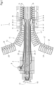
- the device shown for producing composite pipes has two extruders 1, 2. These are each driven by a speed-adjustable drive motor 3, 3' which - with respect to a conveying direction 4 of the entire device - is provided upstream of feed hoppers 5 of the extruders 1, 2.
- a cross-spray head 8 is attached to an extruder 1 arranged in alignment with the molding machine 6 and the post-cooling device 7 and projects into the molding machine 6.
- the other extruder 2 arranged to the side of this extruder 1 is connected to the cross-spray head 8 via an injection channel 9 which opens laterally into the cross-spray head 8.
- a composite pipe 10 is formed in the forming machine 6, which exits the forming machine 6 in the conveying direction 4 and is cooled in the post-cooling device 7. Behind this post-cooling device 7 it can then be cut into pieces of suitable length.
- the forming machine 6 is known in its construction and is described, for example, in EP 0 563 575 A2 described, to which explicit reference is made.
- the transverse injection head 8 has two melt channels arranged concentrically to a common central longitudinal axis 18, namely an inner melt channel 19 and an outer melt channel 20, which - with respect to the conveying direction 4 - end downstream in an inner nozzle 21 and an outer nozzle 22, respectively.
- the inner melt channel 19 is connected to an injection channel 23 of the extruder 1 arranged in alignment with the molding machine 6, whereas the outer melt channel 20 is connected to the injection channel 9 of the other extruder 2.
- a calibration mandrel 24 is attached to the latter, which also runs concentrically to the central longitudinal axis 18. It has cooling channels 25 for cooling medium, in particular cooling water, which is supplied via a cooling water feed line 26 and discharged via a cooling water return line 27.
- the lines 26, 27 can be guided through an approximately tubular supply channel formed concentrically to the central longitudinal axis 18 in the spray head 8. Alternatively, the lines 26, 27 can also be integrated in the calibration mandrel 24, as in Fig. 3 and 4 shown.
- the half moulds 12, 12' have ring-shaped mould recesses 28 which are arranged one behind the other at regular intervals and which are each connected to partial vacuum channels 29.
- the partial vacuum channels 29 - as Fig. 2 can be removed - to partial vacuum supply sources 30, 31, so that the mold recesses 28 are subjected to partial vacuum.
- Plastic melt is fed from the extruder 1 through the injection channel 23 to the transverse injection head 8 and flows through the inner melt channel 19 to the inner nozzle 21 and exits there as an inner tube 34, which reaches the calibration mandrel 24. This expands slightly outwards from the inner nozzle 21 in the conveying direction 4 until the inner tube 34 reaches the corrugation troughs 35 of the outer tube 32 and is welded to it.
- the inner tube 34 and the outer tube 32 form a pipe base body of the composite pipe 10.
- the half-molds 12, 12' are designed such that pipe sleeves 36 are formed at predetermined intervals within the endlessly produced composite pipe 10.
- a substantially cylindrical sleeve recess 37 is formed in a pair of half-molds 12, 12', which thus has a substantially smooth, cylindrical wall 38.
- a transition section 39 is formed between the wall 38 of the sleeve recess 37 and the mold recess 28 leading in the conveying direction 4.
- the end of the wall 38 of the sleeve recess 37 trailing - in the conveying direction 4 - is followed by a frustoconical mold section 40 in which an outwardly expanding inlet end 41 of the sleeve 36 is formed.
- This is in turn followed by a transition section 42 which leads to the next mold recess 28 trailing in the conveying direction 4.
- the calibration mandrel 24 is used to cool and calibrate the inner tube 34 during composite tube production.
- the calibration mandrel is a cooling/calibration mandrel.
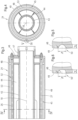
- the calibration mandrel 24 has a support tube 43 oriented concentrically to the central longitudinal axis 18, on the outside of which several support webs 44, four according to the embodiment shown, oriented radially with respect to the central longitudinal axis 18 are arranged.
- a cooling jacket 45 with a cooling mandrel core 52 is arranged concentrically to the support tube 43, in which the cooling water supply line 26 and the cooling water return line 27 are integrated.
- the cooling jacket 45 is axially secured to the support tube 43 with respect to the central longitudinal axis 18 by means of a retaining disk 46 and an axial sleeve 47.
- the retaining disk 46 is designed as an annular disk and is attached to the cooling mandrel core 52 at its outer diameter.
- the cooling jacket 45 is, in particular in the region of its axial end, designed in such a stepped manner that the outer sleeve 48 is arranged at a radial distance from the cooling mandrel core 52.
- the cooling jacket 45 comprises the tubular cooling mandrel core 52.
- the cooling water supply line 26 and the cooling water return line 27 are arranged in the cooling mandrel core 52, in particular diametrically opposite with respect to the central longitudinal axis 18.
- the lines 26, 27 run parallel to the central longitudinal axis 18.
- An annular gap 53 is formed between the cooling mandrel core 52 and the outer sleeve 48, which serves as a cooling section for the calibration mandrel 24.
- An outer sleeve 48 is arranged on the cooling jacket 45 and is held thereon.
- the outer sleeve 48 is designed as a hollow cylinder and has a shaped structure 50 on its outer side 49, which Fig.5
- the mold structure 50 is designed as an external groove on the outer sleeve 48.
- the external groove has in the plane oriented perpendicular to the central longitudinal axis 18, which corresponds to the plane of the drawing in Fig.4 corresponds to a semicircular shape with a groove depth t N and a groove width b N .
- the groove width b N is twice as large as the groove depth trr.
- the groove contour is rounded with a rounding radius r of at least 2.0 mm.
- the shaped structure 50' can also be essentially rectangular, with a groove depth t N ' and a groove width brr ⁇ .
- the groove width brr ⁇ is approximately twice as large as the groove depth t N '.
- b N ' 1.0 ⁇ t N ' ... 3.0 ⁇ t N '.
- the groove contour is rounded at the transition to the outer side 49 and in the groove base with rounding radii r'.
- the Fig. 7 to 9 The calibration mandrel 24' shown corresponds in terms of its basic structure to the calibration mandrel 24, to which reference is hereby made.
- the only difference in the calibration mandrel 24' is the design of the mold structure 54, which is designed as a raised web on the outside 49 of the outer sleeve 48.
- the web can, as in Fig.9 shown, have a semicircular shape, with a web height h s and a web width bs. In the transition area of the web contour to the outer side 49, rounding radii r are present which are at least 2.0 mm.
- the inner tube 34 has an integrally formed, i.e. one-piece molded, guide element 57.
- the contour of the guide element 57 corresponds to the contour of the mold structure 50.
- the guide element 57 extends parallel to the longitudinal axis 55 of the tube.
- the guide element 57 is axially oriented.
- the guide element 57 forms a guide web or a guide rail.
- the guide element 57 projects into the pipe interior enclosed by the pipe base body with a first height hi which is at least 1.0% of the inner diameter d i of the inner pipe 34.
- h 1 1.5% ⁇ d i , in particular 2.0% ⁇ d i and in particular h 1 ⁇ 2.5% ⁇ d i .
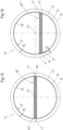
- h 1 t N .
- the separating element 58' is held in the inner tube 34 with two guide elements 57, the design freedom with regard to the geometry of the separating element 58' is increased.
- the separating element 58' can be T-shaped, i.e. it only has three webs 59. This makes it possible to divide the plastic tube 10 into three, in particular different-sized, sub-channels 61.
- separating element 58" is designed in the form of a plate with corresponding end face contours 60 on both sides.
- the separating element 58" is held exclusively on the guide elements 57. Additional webs, in particular those oriented transversely to the plane of the plate, for support on the inside of the pipe 56 are unnecessary.
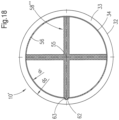
- the guide element 62 is designed according to the shape structure 54 according to Fig. 7 to 9 designed as a groove.
- the separating element 5 8 ⁇ ⁇ ⁇ is mounted and held in place in a similar manner.
- the separating element 5 8 ⁇ ⁇ ⁇ has a front face contour 63 corresponding to the guide element 62, which is designed as a web-like elevation. It is understood that even with the groove-like guide element 62, several guide elements can be formed on the inner side 56 of the pipe, in particular diametrically opposite one another.
- the first height h 1 ' is defined in particular by the web height h s of the mold structure 54.
- Two guide elements 57 are arranged adjacent to one another in a circumferential direction around the pipe's longitudinal axis 55.
- a guide gap 64 is formed between the two adjacent guide elements 57, in which the separating element 58" is held.
- This arrangement is particularly robust. In particular, this arrangement enables the separating element 58"" to be positioned off-center with respect to the pipe's longitudinal axis 55.
- the adjacent guide elements 57 each have a second height h 2 , which can in particular be smaller than the first height h 1 .
- h 2 ⁇ 0.5 % xd i in particular h 2 ⁇ 0.8 % xd i , in particular h 2 ⁇ 1.0 % xd i and in particular h 2 ⁇ 1.5 % xd i .
Landscapes
- Engineering & Computer Science (AREA)
- Mechanical Engineering (AREA)
- General Engineering & Computer Science (AREA)
- Manufacturing & Machinery (AREA)
- Physics & Mathematics (AREA)
- Thermal Sciences (AREA)
- Architecture (AREA)
- Civil Engineering (AREA)
- Structural Engineering (AREA)
- Extrusion Moulding Of Plastics Or The Like (AREA)
- Rigid Pipes And Flexible Pipes (AREA)
- Shaping Of Tube Ends By Bending Or Straightening (AREA)
Abstract
Description
- Die Erfindung betrifft ein Kunststoffrohr sowie eine Vorrichtung zur kontinuierlichen Herstellung eines Rohrgrundkörpers für ein derartiges Kunststoffrohr.
- Rohre mit mehreren innenliegenden Kammern, die auch als Mehrfachkanäle bezeichnet werden, finden für die Wasseraufbereitung in der Abwassertechnik oder als Kabelschutzrohre Anwendung. In Kabelschutzrohre wird beispielsweise ein Rohrbündel mit mehreren miteinander verbundenen Innenrohren eingezogen. Die Herstellung und insbesondere die Installation der Kabelschutzrohre ist aufwändig. Die Herstellung von Kunststoffrohren mit innenliegender Trennwand weist Limitationen mit Blick auf die Gestaltungsfreiheit des Kunststoffrohres auf. Für die Anordnung und Befestigung der Trennwand müssen separate Befestigungsmittel an der Rohrinnenseite angebracht werden. Die Herstellung muss in mehreren Schritten und durch manuelle Zusatztätigkeiten erfolgen.
- Der Erfindung liegt die Aufgabe zugrunde, die Herstellung eines Kunststoffrohres mit Mehrfachkanälen und mit gewellter oder gerippter Außenseite zu vereinfachen.
- Diese Aufgabe ist durch ein Kunststoffrohr mit den im Anspruch 1 angegebenen Merkmalen sowie durch eine Vorrichtung im Anspruch 11 angegebenen Merkmalen gelöst.
- Erfindungsgemäß wurde erkannt, dass an einer, insbesondere glatten, Rohrinnenseite eines Kunststoffrohres mindestens ein Führungselement integral ausgebildet werden kann. Das mindestens eine Führungselement dient zum Halten eines Trennelements, das den Rohrinnenraum in Mehrfachkanäle unterteilt. Das Trennelement dient als Trennwand zur Kanaltrennung im Kunststoffrohr. Das Trennelement kann seitliche Durchbrüche aufweisen, um eine Verbindung zwischen den getrennten Kanälen zu ermöglichen. Die Durchbrüche können beispielsweise bei einer Wasseraufbereitung und/oder bei einer Wasservorreinigung hilfreich sein.
- Das Trennelement kann an dem mindestens einen Führungselement definiert und insbesondere unkompliziert positioniert werden. Insbesondere ist das Trennelement in Umfangsrichtung um die Rohrlängsachse ortsfest und insbesondere winkelgenau festgelegt. Das Trennelement kann in axialer Richtung in das Kunststoffrohr eingeschoben werden. Die Herstellung ist vereinfacht.
- Das Trennelement kann durch Kunststoff-Spritzguss oder in einem additiven Verfahren, insbesondere durch 3D-Druckverfahren hergestellt werden. Das Trennelement kann auch manuell hergestellt werden.
- Das mindestens eine Führungselement ist entlang der Rohrlängsachse orientiert, also axial ausgerichtet. Das mindestens eine Führungselement ist einteilig an der Rohrinnenseite angeformt. Die Rohrinnenseite ist mit Ausnahme des mindestens einen Führungselements zylindrisch ausgeführt. Die Rohraußenseite des Kunststoffrohres weist senkrecht zu der Rohrlängsachse orientierte Erhebungen auf. Das Kunststoffrohr ist insbesondere ein Verbundrohr mit einem glatten Innenrohr und einem damit verbundenen, insbesondere verschweißten, gewellten Außenrohr, wie es beispielsweise aus
EP 0 563 575 A2 bekannt ist. Das Kunststoffrohr kann auch ein Rippenrohr gemäßEP 0 531 750 A2 sein. Die Herstellung derartiger Rippenrohre ist bekannt ausDE 24 50 171 C2 . - Das Kunststoffrohr, insbesondere der Rohrgrundkörper und das Trennelement, ist aus einem Kunststoffmaterial, insbesondere aus thermoplastischem Kunststoffmaterial hergestellt.
- Das Trennelement ist insbesondere an mindestens einer weiteren Stützstelle an der Rohrinnenseite abgestützt und zuverlässig, insbesondere verdrehsicher bezüglich der Rohrlängsachse, in dem Kunststoffrohr gehalten. Es ist auch denkbar, mehrere Trennelemente zu verwenden, die jeweils an mindestens einem Führungselement gehalten sind.
- Ein Verbundrohr gemäß Anspruch 2 eignet sich insbesondere für die Wasseraufbereitung. Das Verbundrohr weist insbesondere einen Innendurchmesser auf, der mindestens 100 mm beträgt. Eine typische Durchmesserrelation des Verbundrohres von Außendurchmesser zu Innendurchmesser beträgt mindestens 1,15, insbesondere mindestens 1,20 und insbesondere mindestens 1,25. Typische Durchmesser-Fertigungstoleranzen bezogen auf den Außendurchmesser oder bezogen auf den Innendurchmesser betragen ± 0,25 % bis ± 0,5 %.
- Ein Kunststoffrohr gemäß Anspruch 3 ermöglicht eine hohe Gestaltungsfreiheit hinsichtlich des mindestens einen Führungselements. Insbesondere kann das mindestens eine Führungselement in Abhängigkeit der herzustellenden Kanalaufteilung als Nut, also als radiale Vertiefung an der Rohrinnenseite, oder als Steg, also als radial erhabene Struktur an der Rohrinnenseite, ausgeführt sein.
- Ein Kunststoffrohr gemäß Anspruch 4 ermöglicht eine zuverlässige und insbesondere fehlerfreie Herstellung des mindestens einen Führungselements. Eine abgerundete Kontur des mindestens einen Führungselements vermeidet herstellungsbedingte Fehlstellen. Die verwendeten Rundungsradien sind abhängig vom Nenndurchmesser des Kunststoffrohres und betragen insbesondere mindestens 2,0 mm.
- Ein Kunststoffrohr gemäß Anspruch 5 gewährleistet die zuverlässige und stabile Anordnung des Trennelements mit genau einem Führungselement. Eine Höhe des Führungselements beträgt mindestens 1,0 % des Innendurchmessers und insbesondere mindestens 1,0 % des Außendurchmessers.
- Ein Kunststoffrohr gemäß Anspruch 6 ermöglicht eine stabile Anordnung des Trennelements zwischen zwei in Umfangsrichtung um die Rohrlängsachse benachbart angeordneten Führungselementen. Zwischen den Führungselementen ist ein Führungsspalt gebildet, in dem das mindestens eine Trennelement angeordnet und darin gehalten ist.
- Ein Kunststoffrohr gemäß Anspruch 7 weist mehrere, insbesondere gegenüberliegend angeordnete Führungselemente auf. Gegenüberliegend bedeutet insbesondere diametral gegenüberliegend bezüglich der Rohrlängsachse, also mit einem Drehwinkel von 180° bezüglich der Rohrlängsachse. Gegenüberliegend im Sinne des Anspruchs bedeutet aber auch einen Drehwinkel bezüglich der Rohrlängsachse, der kleiner ist als 180° und insbesondere mindestens 90° beträgt. Das Trennelement ist insbesondere an den mehreren Führungselementen jeweils gehalten.
- Ein Kunststoffrohr gemäß Anspruch 8 ermöglicht eine zuverlässige Befestigung des Trennelements an mehreren Führungselementen. Die dafür erforderliche Höhe der Führungselemente beträgt mindestens 0,5 % des Innendurchmessers und insbesondere mindestens 0,5 % des Außendurchmessers.
- Die Ausführung des Trennelements als Platte gemäß Anspruch 9 ist unkompliziert und kosteneffizient. In Abhängigkeit der Anwendung, insbesondere der Anzahl der erforderlichen Kanäle, kann das Trennelement als offenes Profil, insbesondere als Kreuzprofil ausgeführt sein. Das Trennelement kann in einer zur Rohrlängsachse senkrechten Ebene mehrere Stege aufweisen, die insbesondere so angeordnet sein können, dass unterschiedlich große Kanäle im Rohr gebildet werden. Das Trennelement ermöglicht einen großen Gestaltungsspielraum bei der Ausbildung der Innenkanäle.
- Bei dem Kunststoffrohr gemäß Anspruch 10 ist das Trennelement besonders stabil angeordnet. Mit einer mindestens dem mindestens einen Führungselement korrespondierenden Stirnseitenkontur ist das Trennelement formschlüssig in Umfangsrichtung um die Rohrlängsachse in dem Kunststoffrohr angeordnet.
- Eine Vorrichtung gemäß Anspruch 11 ermöglicht die kontinuierliche Herstellung eines Rohrgrundkörpers für ein Kunststoffrohr. Die Vorrichtung umfasst eine an sich bekannte Formstrecke mit Halbkokillen und einen Spritzkopf mit Außendüse zur Extrusion eines Außenrohres und mit einer Innendüse zur Extrusion eines Innenrohres mit glatter Rohrinnenseite. Am Ende des Spritzkopfes ist ein Kalibrierdorn angeordnet, der zum Kühlen und Kalibrieren des Innenrohres dient. Dazu weist der Kalibrierdorn ein Tragrohr, einen daran gehaltenen Kühlmantel und eine daran gehaltene Außenhülse auf. Die im Wesentlichen zylindrisch ausgebildete Außenhülse hat mindestens eine Formstruktur, die zum integralen Ausbilden des mindestens einen Führungselements an der glatten Rohrinnenseite dient. Dadurch ist es möglich, das mindestens eine Führungselement in einem kontinuierlichen Verfahren, insbesondere durch Extrusion des Rohrgrundkörpers, herzustellen. In den Rohrgrundkörper mit dem mindestens einen Führungselement wird das Trennelement nachträglich axial eingeschoben.
- Weitere Merkmale, Vorteile und Einzelheiten der Erfindung ergeben sich aus der nachfolgenden Beschreibung von Ausführungsbeispielen anhand der Zeichnung. Es zeigen:
- Fig. 1
- eine Vorrichtung zur kontinuierlichen Herstellung eines Rohrgrundkörpers eines erfindungsgemäßen Kunststoffrohres,
- Fig. 2
- einen Längsschnitt eines Spritzkopfes der Vorrichtung in
Fig. 1 , - Fig. 3
- eine vergrößerte Detaildarstellung im Längsschnitt eines Kühldorns des Spritzkopfes gemäß
Fig. 2 mit einer nutförmigen Formstruktur, - Fig. 4
- eine Schnittdarstellung gemäß Schnittlinie IV-IV in
Fig. 3 , - Fig. 5
- eine vergrößerte Detaildarstellung einer Formstruktur gemäß Detail V in
Fig. 4 , - Fig. 6
- eine
Fig. 5 entsprechende Darstellung einer geänderten Formstruktur gemäß einem weiteren Ausführungsbeispiel, - Fig. 7 bis 9
-
Fig. 3 bis 5 entsprechende Darstellungen eines Kühldorns mit erhabener Formstruktur, - Fig. 10
- eine
Fig. 9 entsprechende Darstellung einer Formstruktur gemäß einem weiteren Ausführungsbeispiel, - Fig. 11 bis 13
- eine teilgeschnittene Seitenansicht eines erfindungsgemäßen Kunststoffrohres als Verbundrohr mit einem als Steg ausgeführten Führungselement mit kreuzprofilförmigem Trennelement,
- Fig. 14 und 15
- weitere Ausführungsbeispiele von Kunststoffrohren mit gegenüberliegend angeordneten Führungselementen und mit verschiedenartigen Trennelementen,
- Fig. 16 bis 18
-
Fig. 11 bis 13 entsprechende Darstellungen eines Verbundrohres gemäß einem weiteren Ausführungsbeispiel mit einem als Nut ausgeführten Führungselement, - Fig. 19
- eine
Fig. 18 entsprechende Darstellung eines Kunststoffrohrs gemäß einem weiteren Ausführungsbeispiel mit zwei benachbart angeordneten, jeweils als Steg ausgeführten Führungselementen und einem dazwischen angeordneten Trennelement. - Eine in
Fig. 1 dargestellte Vorrichtung zur Herstellung von Verbundrohren weist zwei Extruder 1, 2 auf. Diese werden jeweils von einem drehzahlregelbaren Antriebsmotor 3, 3' angetrieben, der - bezogen auf eine Förderrichtung 4 der gesamten Vorrichtung - stromaufwärts von Zuführtrichtern 5 der Extruder 1, 2 vorgesehen ist. - Bezogen auf die Förderrichtung 4 stromabwärts von den Extrudern 1, 2 ist eine Formmaschine 6, ein sogenannter Corrugator, angeordnet, dem wiederum eine Nachkühlvorrichtung 7 nachgeordnet ist. An einem fluchtend mit der Formmaschine 6 und der Nachkühlvorrichtung 7 angeordneten Extruder 1 ist ein Quer-Spritzkopf 8 angebracht, der in die Formmaschine 6 hineinragt. Der andere, seitlich dieses Extruders 1 angeordnete Extruder 2 ist über einen seitlich in den Quer-Spritzkopf 8 einmündenden Spritzkanal 9 mit dem Quer-Spritzkopf 8 verbunden. Wie schematisch in
Fig. 1 angedeutet ist, wird in der Formmaschine 6 ein Verbundrohr 10 geformt, das in Förderrichtung 4 aus der Formmaschine 6 austritt und in der Nachkühlvorrichtung 7 abgekühlt wird. Hinter dieser Nachkühlvorrichtung 7 kann es dann in Stücke geeigneter Länge geschnitten werden. Die Formmaschine 6 ist in ihrem Aufbau bekannt und beispielsweise in derEP 0 563 575 A2 beschrieben, worauf ausdrücklich verwiesen wird. - Sie weist im Wesentlichen einen Maschinentisch 11 auf, auf dem Halbkokillen 12, 12' angeordnet sind, die jeweils zu zwei sogenannten Ketten 13, 13' miteinander verbunden sind. Diese Ketten 13, 13' werden am - bezogen auf die Förderrichtung 4 - stromaufwärtigen Einlaufende 14 und an ihrem stromabwärtigen Auslaufende 15 über nicht dargestellte Umlenkrollen geführt. Sie werden bei dem Umlauf in Förderrichtung 4 derart geführt, dass jeweils zwei Halbkokillen 12, 12' zu einem Kokillen-Paar vereinigt werden, wobei wiederum in Förderrichtung 4 hintereinander folgende Kokillen-Paare dicht an dicht liegen. Der Antrieb der auf einer Formstrecke 16 jeweils zu Kokillen-Paaren zusammengeführten Halbkokillen 12, 12' erfolgt mittels eines Antriebsmotors 17.
- Der Quer-Spritzkopf 8 weist zwei konzentrisch zu einer gemeinsamen Mittellängsachse 18 angeordnete Schmelzekanäle, nämlich einen inneren Schmelzekanal 19 und einen äußeren Schmelzekanal 20, die - bezogen auf die Förderrichtung 4 - stromabwärts in einer Innendüse 21 bzw. einer Au-ßendüse 22 enden. Der innere Schmelzekanal 19 ist an einem Spritzkanal 23 des fluchtend mit der Formmaschine 6 angeordneten Extruders 1 angeschlossen, wogegen der äußere Schmelzekanal 20 an den Spritzkanal 9 des anderen Extruders 2 angeschlossen ist.
- Am - bezogen auf die Förderrichtung 4 - stromabwärtigen Ende des Spritzkopfes 8 ist an diesem ein Kalibrierdorn 24 angebracht, der ebenfalls konzentrisch zur Mittellängsachse 18 verläuft. Er weist Kühlkanäle 25 für Kühlmedium, insbesondere Kühlwasser, auf, das über eine Kühlwasser-Vorlaufleitung 26 zugeführt und eine Kühlwasser-Rücklaufleitung 27 abgeführt wird. Die Leitungen 26, 27 können durch einen konzentrisch zur Mittellängsachse 18 im Spritzkopf 8 ausgebildeten, etwa rohrförmigen Versorgungskanal geführt sein. Alternativ können die Leitungen 26, 27 auch im Kalibrierdorn 24 integriert ausgeführt sein, wie in
Fig. 3 und 4 dargestellt. - Die Halbkokillen 12, 12' weisen ringförmige Formausnehmungen 28 auf, die in regelmäßigen Abständen hintereinander angeordnet sind und die jeweils an Teilvakuumkanälen 29 angeschlossen sind. Beim Einlauf der Halbkokillen 12, 12' in die Formstrecke 16 gelangen die Teilvakuumkanäle 29 - wie
Fig. 2 entnehmbar ist - an Teilvakuumversorgungsquellen 30, 31, so dass die Formausnehmungen 28 mit Teilvakuum beaufschlagt werden. - Die vom Extruder 2 durch den Spritzkanal 9 dem Spritzkopf 8 zugeführte Kunststoffschmelze strömt durch den äußeren Schmelzekanal 20 zur Au-ßendüse 22 und wird dort unter Formung eines Außenrohres 32 extrudiert. Aufgrund des Teilvakuums legt sich das Außenrohr 32 unter Formung eines mit Querrillen versehenen Rohres in die Formausnehmungen 28. Die Querrillen bilden Erhebungen 33 an der Rohraußenseite. Aus dem Extruder 1 wird durch den Spritzkanal 23 dem Quer-Spritzkopf 8 Kunststoffschmelze zugeführt und strömt durch den inneren Schmelzekanal 19 zur Innendüse 21 und tritt dort als Innenrohr 34 aus, das auf den Kalibrierdorn 24 gelangt. Dieser erweitert sich von der Innendüse 21 in Förderrichtung 4 leicht nach außen, bis das Innenrohr 34 gegen die Wellentäler 35 des Außenrohres 32 gelangt und mit diesem verschweißt wird.
- Das Innenrohr 34 und das Außenrohr 32 bilden nach Abkühlung und Erstarrung einen Rohrgrundkörper des Verbundrohres 10.
- Wie insbesondere in
Fig. 2 ersichtlich ist, sind die Halbkokillen 12, 12' so ausgebildet, dass jeweils in vorgegebenen Abständen innerhalb des endlos hergestellten Verbundrohres 10 Rohrmuffen 36 ausgebildet werden. Hierzu ist in einem Paar von Halbkokillen 12, 12' eine im Wesentlichen zylindrische Muffenausnehmung 37 ausgebildet, die also eine im Wesentlichen glatte, zylindrische Wand 38 aufweist. - Zwischen der Wand 38 der Muffenausnehmung 37 und der in Förderrichtung 4 voreilenden Formausnehmung 28 ist ein Übergangsabschnitt 39 ausgebildet. An das - in Förderrichtung 4 - nacheilende Ende der Wand 38 der Muffenausnehmung 37 schließt sich ein kegelstumpfförmiger Formabschnitt 40 an, in dem ein sich nach außen erweiterndes Einführende 41 der Muffe 36 ausgeformt wird. Daran schließt sich wiederum ein Übergangsabschnitt 42 an, der zur nächsten - in Förderrichtung 4 nacheilenden - Formausnehmung 28 führt.
- Soweit die Vorrichtung bis hierher beschrieben ist, ist sie im Wesentlichen aus
EP 0 995 579 A2 bekannt, worauf ausdrücklich verwiesen wird. - Nachfolgend wird anhand von
Fig. 3 bis 5 eine besondere Ausgestaltung des Kalibrierdorns 24 näher erläutert. Der Kalibrierdorn 24 dient zum Kühlen und Kalibrieren des Innenrohres 34 bei der Verbundrohrherstellung. Der Kalibrierdorn ist ein Kühl-/Kalibrierdorn. - Der Kalibrierdorn 24 weist ein konzentrisch zur Mittellängsachse 18 orientiertes Tragrohr 43 auf, an dessen Außenseite mehrere, gemäß dem gezeigten Ausführungsbeispiel vier, radial bezüglich der Mittellängsachse 18 orientierte Stützstege 44 angeordnet sind.
- Konzentrisch zu dem Tragrohr 43 ist ein Kühlmantel 45 mit einem Kühldornkern 52 angeordnet, in dem die Kühlwasser-Vorlaufleitung 26 und die Kühlwasser-Rücklaufleitung 27 integriert sind. Der Kühlmantel 45 ist axial bezüglich der Mittellängsachse 18 an dem Tragrohr 43 mittels einer Haltescheibe 46 und einer Axialhülse 47 axial gesichert. Die Haltescheibe 46 ist als Ringscheibe ausgeführt und an ihrem Außendurchmesser an dem Kühldornkern 52 befestigt.
- Der Kühlmantel 45 ist, insbesondere im Bereich seines axialen Endes, insbesondere derart gestuft ausgeführt, dass die Außenhülse 48 radial beabstandet zu dem Kühldornkern 52 angeordnet ist. Der Kühlmantel 45 umfasst den rohrförmigen Kühldornkern 52. In dem Kühldornkern 52 sind die Kühlwasser-Vorlaufleitung 26 und die Kühlwasser-Rücklaufleitung 27 angeordnet, insbesondere bezüglich der Mittellängsachse 18 diametral gegenüberliegend. Die Leitungen 26, 27 verlaufen parallel zur Mittellängsachse 18.
- Zwischen dem Kühldornkern 52 und der Außenhülse 48 ist ein Ringspalt 53 gebildet, der als Kühlstrecke für den Kalibrierdorn 24 dient.
- An dem Kühlmantel 45 ist eine Außenhülse 48 angeordnet und daran gehalten. Die Außenhülse 48 ist hohlzylindrisch ausgeführt und weist an ihrer Außenseite 49 eine Formstruktur 50 auf, die in
Fig. 5 vergrößert dargestellt ist. Die Formstruktur 50 ist als Außennut an der Außenhülse 48 ausgeführt. Die Außennut weist in der zur Mittellängsachse 18 senkrecht orientierten Ebene, die der Zeichenebene inFig. 4 entspricht, eine Halbkreisform auf mit einer Nuttiefe tN und einer Nutbreite bN. Bei der halbkreisförmigen Ausgestaltung ist die Nutbreite bN doppelt so groß wie die Nuttiefe trr. An dem Übergang zur Außenseite 49 ist die Nutkontur mit einem Rundungsradius r von mindestens 2,0 mm abgerundet. Wenn das Innenrohr 34 bei der Herstellung des Verbundrohres 10 über den Kalibrierdorn 24 gekühlt und kalibriert wird, bildet sich in der Formstruktur 50 an dem Innenrohr 34 ein korrespondierendes Führungselement 57 aus, das anhand vonFig. 11 bis 13 noch näher erläutert wird. - Wie in
Fig. 6 dargestellt, kann die Formstruktur 50' auch im Wesentlichen rechteckförmig ausgeführt sein, mit einer Nuttiefe tN' und einer Nutbreite brr`. Gemäß dem gezeigten Ausführungsbeispiel ist die Nutbreite brr` etwa doppelt so groß wie die Nuttiefe tN'. Insbesondere gilt: bN' = 1,0 × tN' ... 3,0 × tN'. Die Nutkontur ist am Übergang zur Außenseite 49 und im Nutgrund mit Rundungsradien r' abgerundet. - Der in
Fig. 7 bis 9 dargestellte Kalibrierdorn 24' entspricht bezüglich seines Grundaufbaus dem Kalibrierdorn 24, worauf hiermit verwiesen wird. - Einziger Unterschied bei dem Kalibrierdorn 24' ist die Ausgestaltung der Formstruktur 54, die als erhabener Steg an der Außenseite 49 der Außenhülse 48 ausgebildet ist. Der Steg kann, wie in
Fig. 9 gezeigt, eine Halbkreisform aufweisen, mit einer Steghöhe hs und einer Stegbreite bs. Im Übergangsbereich der Stegkontur zur Außenseite 49 sind Rundungsradien r vorhanden, die mindestens 2,0 mm betragen. - Wie in
Fig. 10 gezeigt, kann die stegartige Formstruktur 54' im Wesentlichen rechteckförmig ausgeführt mit einer Steghöhe hs`, einer Stegbreite bs` und entsprechenden Rundungsradien r'. Insbesondere gilt: bs` = 1,0 x hs' ... 3,0 x hs'. - Ein mit der Vorrichtung und dem Kühldorn 24 gemäß
Fig. 3 bis 5 hergestellter Rohrgrundkörper des Verbundrohres 10 ist inFig. 11 bis 13 dargestellt. Das Verbundrohr 10 ist ein Kunststoffrohr und weist eine Rohrlängsachse 55 auf. Bei dem Verbundrohr 10 ist das Innenrohr 34 mit dem Außenrohr 32 im Bereich der Wellentäler 35 verschweißt. Bei dem Außenrohr 32 sind die Querrillen als senkrecht zur Rohrlängsachse 55 orientierte Erhebungen 33 ausgebildet. Das Außenrohr 32 bildet eine Rohraußenseite des Verbundrohres 10. Das Innenrohr 34 ist bezüglich der Rohrlängsachse 55 zylindrisch ausgeführt mit einer glatten Rohrinnenseite 56. - Infolge der nutförmigen Formstruktur 50 des Kalibrierdorns 24 weist das Innenrohr 34 ein integral ausgebildetes, also einteilig angeformtes, Führungselement 57 auf. Die Kontur des Führungselements 57 korrespondiert zu der Kontur der Formstruktur 50. Das Führungselement 57 erstreckt sich parallel zur Rohrlängsachse 55. Das Führungselement 57 ist axial orientiert. Das Führungselement 57 bildet einen Führungssteg oder eine Führungsschiene.
- Das Führungselement 57 ragt in den vom Rohrgrundkörper umschlossenen Rohrinnenraum vor mit einer ersten Höhe hi, die mindestens 1,0 % des Innendurchmessers di des Innenrohrs 34 beträgt. Insbesondere gilt: h1 ≥ 1,5 % × di, insbesondere 2,0 % × di und insbesondere h1 ≥ 2,5 % × di. Insbesondere gilt h1 = tN.
- An dem Führungselement 57 ist bei dem erfindungsgemäßen Kunststoffrohr gemäß
Fig. 13 ein Trennelement 58 gehalten. Das Trennelement 58 ist als Kreuzprofil ausgeführt und konzentrisch zur Rohrlängsachse 55 angeordnet. Das Trennelement 58 weist zwei sich kreuzende Stege 59 auf, die zentral und einteilig miteinander verbunden sind. Der dem Führungselement 57 zugewandte Steg 59 weist eine dem Führungselement 57 korrespondierende Stirnseitenkontur 60 auf, mit der das Trennelement 58 in das Innenrohr 34 einschiebbar und an dem Führungselement 57 gehalten ist. Das Trennelement 58 ist verdrehsicher und winkelgenau bezüglich der Rohrlängsachse 55 in dem Verbundrohr 10 gehalten. Mit dem Trennelement 58 wird der Rohrinnenraum des Verbundrohres 10 in vier, insbesondere gleich große, Teilkanäle 61 unterteilt. Das Führungselement 57 garantiert eine Verdrehsicherung des Trennelements 58 bezüglich der Rohrlängsachse 55. Mit den drei übrigen Stirnseiten der Stege 59 ist das Trennelement 58 jeweils an der Rohrinnenseite 56 abgestützt. Das Trennelement 58 ist robust in dem Rohrgrundkörper angeordnet. Eine unbeabsichtigte Veränderung der Drehposition des Trennelements 58 ist zuverlässig verhindert. - Gemäß einem weiteren Ausführungsbeispiel gemäß
Fig. 14 sind zwei Führungselemente 57 an dem Innenrohr 34 ausgebildet. Die Führungselemente 57 sind bezüglich der Rohrlängsachse 55 diametral gegenüberliegend zueinander angeordnet. - Dadurch, dass das Trennelement 58' mit zwei Führungselementen 57 in dem Innenrohr 34 gehalten ist, ist der Gestaltungsspielraum bezüglich der Geometrie des Trennelements 58' erhöht. Das Trennelement 58' kann T-förmig ausgeführt sein, weist also nur drei Stege 59 auf. Dadurch ist es möglich, das Kunststoffrohr 10 in drei, insbesondere verschieden große, Teilkanäle 61 zu unterteilen.
- Bei dem Ausführungsbeispiel des Verbundrohres 10 gemäß
Fig. 15 sind - wie inFig. 14 - zwei gegenüberliegende Führungselemente 57 ausgebildet. Das Trennelement 58" ist plattenförmig ausgeführt mit beidseitig entsprechenden Stirnseitenkonturen 60. Das Trennelement 58" ist ausschließlich an den Führungselementen 57 gehalten. Weitere, insbesondere quer zur Plattenebene orientierte Stege zur Abstützung an der Rohrinnenseite 56 sind entbehrlich. - Bei einem weiteren Ausführungsbeispiel eines Verbundrohres 10' gemäß
Fig. 16 bis 18 ist das Führungselement 62 entsprechend der Formstruktur 54 gemäßFig. 7 bis 9 als Nut ausgeführt. Montage und Halterung des Trennelements 5 8 ` ` ` erfolgen analog. Das Trennelement 5 8 ` ` ` weist eine dem Führungselement 62 korrespondierende Stirnseitenkontur 63 auf, die als stegartige Erhebung ausgeführt ist. Es versteht sich, dass auch bei dem nutartigen Führungselement 62 mehrere Führungselemente an der Rohrinnenseite 56 ausgebildet sein können, insbesondere diametral gegenüberliegend. - Die erste Höhe h1' ist insbesondere durch die Steghöhe hs der Formstruktur 54 definiert.
- Bei dem Ausführungsbeispiel eines Verbundrohres 10" gemäß
Fig. 19 sind jeweils zwei Führungselemente 57 benachbart zueinander bezüglich einer Umfangsrichtung um die Rohrlängsachse 55 angeordnet. Zwischen den beiden benachbarten Führungselementen 57 wird ein Führungsspalt 64 gebildet, in dem das Trennelement 58‴′ gehalten ist. Diese Anordnung ist besonders robust. Insbesondere ermöglicht diese Anordnung eine bezüglich der Rohrlängsachse 55 außermittige Positionierung des Trennelements 58"". - Die benachbarten Führungselemente 57 weisen jeweils eine zweite Höhe h2 auf, die insbesondere kleiner ausgeführt sein kann als die erste Höhe h1. Insbesondere gilt: h2 ≥ 0,5 % x di, insbesondere h2 ≥ 0,8 % x di, insbesondere h2 ≥ 1,0 % x di und insbesondere h2 ≥ 1,5 % x di.
Claims (11)
- Kunststoffrohr mita. senkrecht zu einer Rohrlängsachse (55) orientierten Erhebungen (33) an einer Rohraußenseite,b. einer Rohrinnenseite (56), an der mindestens ein parallel zur Rohrlängsachse (55) orientiertes Führungselement (57; 62) integral ausgebildet ist,c. einem an dem mindestens einen Führungselement (57; 62) gehaltenen Trennelement (58; 58'; 58"; 58‴; 58ʺʺ).
- Kunststoffrohr gemäß Anspruch 1, dadurch gekennzeichnet, dass das Kunststoffrohr als Verbundrohr (10; 10'; 10") ausgeführt ist mit einem einen Innendurchmesser (di) aufweisenden Innenrohr (34) und mit einem mit dem Innenrohr (34) verschweißten Außenrohr (32), das einen Außendurchmesser (da) aufweist, wobei gilt: da / di ≥ 1,15.
- Kunststoffrohr gemäß einem der vorstehenden Ansprüche, dadurch gekennzeichnet, dass das mindestens eine Führungselement als Nut (62) oder als Steg (57) ausgeführt ist.
- Kunststoffrohr gemäß einem der vorstehenden Ansprüche, dadurch gekennzeichnet, dass das mindestens eine Führungselement (57; 62) in einer zur Rohrlängsachse (55) senkrecht orientierten Ebene eine Kontur aufweist, deren Radien (r; r') mindestens 2,0 mm betragen.
- Kunststoffrohr gemäß einem der vorstehenden Ansprüche, dadurch gekennzeichnet, dass genau ein Führungselement (57; 62) vorhanden ist, das gegenüber der Rohrinnenseite (56) in radialer Richtung bezüglich der Rohrlängsachse (55) eine erste Höhe (h1; h1') aufweist, wobei gilt h1 ≥ 1,0 % · di oder h1' ≥ 1,0% · di.
- Kunststoffrohr gemäß einem der vorstehenden Ansprüche, dadurch gekennzeichnet, dass zwischen zwei in Umfangsrichtung um die Rohrlängsachse (55) benachbart angeordnete Führungselemente (57) ein Führungsspalt (64) gebildet ist, in dem das Trennelement (58ʺʺ) angeordnet ist.
- Kunststoffrohr gemäß einem der vorstehenden Ansprüche, dadurch gekennzeichnet, dass mehrere Führungselemente (57; 62) vorhanden sind, an denen das Trennelement (58'; 58"; 58ʺʺ) gehalten ist.
- Kunststoffrohr gemäß einem der Ansprüche 1 bis 6, dadurch gekennzeichnet, dass mehrere Führungselemente (57; 62) vorhanden sind, die jeweils gegenüber der Rohrinnenseite (56) in radialer Richtung bezüglich der Rohrlängsachse (55) eine zweite Höhe (h2) aufweisen, wobei gilt h2 ≥ 0,5 % · di.
- Kunststoffrohr gemäß einem der vorstehenden Ansprüche, dadurch gekennzeichnet, dass das Trennelement als Platte (58"; 58"") oder als offenes Profil (58; 58`; 58‴), insbesondere als Kreuzprofil, ausgeführt ist.
- Kunststoffrohr gemäß einem der vorstehenden Ansprüche, dadurch gekennzeichnet, dass das Trennelement (58; 58'; 58"; 58‴) eine dem mindestens einen Führungselement (57; 62) korrespondierende Stirnseitenkontur (60; 63) aufweist.
- Vorrichtung zur kontinuierlichen Herstellung eines Rohrgrundkörpers für ein Kunststoffrohr (10; 10') umfassenda. mit ringförmigen Formausnehmungen (28) versehene, sich auf einer Formstrecke (16) jeweils paarweise zu einer Form mit einer Mittellängsachse (18) ergänzende Halbkokillen (12; 12'), die im Kreislauf und in einer Förderrichtung (4) angeordnet sind,b. ein der Formstrecke (16) vorgeordneter Spritzkopf (8) mindestens eines Extruders (1, 2), wobei der Spritzkopf (8) aufweisti. eine Außendüse (22) zur Extrusion eines Außenrohres (32),ii. eine in Förderrichtung (4) nachgeordnete Innendüse (21) zur Extrusion eines Innenrohres (34),iii. einen in Förderrichtung (4) nachgeordneten Kalibrierdorn (24; 24') mit- einem inneren, sich entlang der Mittellängsachse (18) erstreckenden Tragrohr (43),- einem von dem Tragrohr (43) gehaltenen Kühlmantel (45) mit integriertem Kühlkanal (53),- einer an dem Kühlmantel (45) gehaltenen Außenhülse (48) mit mindestens einer Formstruktur (50; 50`; 54; 54') zum integralen Ausbilden des mindestens einen Führungselements (57; 62).
Priority Applications (6)
| Application Number | Priority Date | Filing Date | Title |
|---|---|---|---|
| EP23163153.2A EP4434716B1 (de) | 2023-03-21 | 2023-03-21 | Kunststoffrohr |
| PL23163153.2T PL4434716T3 (pl) | 2023-03-21 | 2023-03-21 | Rura z tworzywa sztucznego |
| DK23163153.2T DK4434716T3 (da) | 2023-03-21 | 2023-03-21 | Plastrør |
| CA3227493A CA3227493A1 (en) | 2023-03-21 | 2024-01-26 | Plastic pipe and device for the continuous production of a pipe base body for a plastic pipe of this type |
| JP2024031174A JP2024137770A (ja) | 2023-03-21 | 2024-03-01 | プラスチックパイプ及びこの種のプラスチックパイプ用のパイプ基体を連続的に製造する装置 |
| US18/612,021 US20240318749A1 (en) | 2023-03-21 | 2024-03-21 | Plastic pipe and device for the continuous production of a pipe base body for a plastic pipe of this type |
Applications Claiming Priority (1)
| Application Number | Priority Date | Filing Date | Title |
|---|---|---|---|
| EP23163153.2A EP4434716B1 (de) | 2023-03-21 | 2023-03-21 | Kunststoffrohr |
Publications (2)
| Publication Number | Publication Date |
|---|---|
| EP4434716A1 true EP4434716A1 (de) | 2024-09-25 |
| EP4434716B1 EP4434716B1 (de) | 2025-07-30 |
Family
ID=85724561
Family Applications (1)
| Application Number | Title | Priority Date | Filing Date |
|---|---|---|---|
| EP23163153.2A Active EP4434716B1 (de) | 2023-03-21 | 2023-03-21 | Kunststoffrohr |
Country Status (6)
| Country | Link |
|---|---|
| US (1) | US20240318749A1 (de) |
| EP (1) | EP4434716B1 (de) |
| JP (1) | JP2024137770A (de) |
| CA (1) | CA3227493A1 (de) |
| DK (1) | DK4434716T3 (de) |
| PL (1) | PL4434716T3 (de) |
Cited By (1)
| Publication number | Priority date | Publication date | Assignee | Title |
|---|---|---|---|---|
| DE102024203507A1 (de) * | 2024-04-16 | 2025-10-16 | Ralph Peter Hegler | Sedimentationsrohr und Rohrsedimentationsanlage mit einem derartigen Sedimentationsrohr |
Citations (9)
| Publication number | Priority date | Publication date | Assignee | Title |
|---|---|---|---|---|
| DE2450171C2 (de) | 1973-10-22 | 1983-04-14 | Wendia Plast AB, Aange | Vorrichtung zum Herstellen von Rippenrohren |
| EP0531750A2 (de) | 1991-09-07 | 1993-03-17 | Wilhelm Hegler | Verfahren zum Verschweissen von aus thermoplastischem Kunststoff bestehenden Rohren |
| EP0563575A2 (de) | 1992-03-31 | 1993-10-06 | Wilhelm Hegler | Verfahren und Vorrichtung zur fortlaufenden Herstellung eines Verbundrohres mit Rohr-Muffe |
| EP0995579A2 (de) | 1998-10-21 | 2000-04-26 | Hegler, Ralph-Peter, Dr.-Ing. | Verfahren zur fortlaufenden Herstellung eines Verbundrohres mit einer Rohr-Muffe und Vorrichtung zur Durchführung des Verfahrens |
| KR20080057795A (ko) * | 2006-12-21 | 2008-06-25 | 임창규 | 통합 배관의 구조 |
| CN101910700A (zh) * | 2007-12-07 | 2010-12-08 | 全贞子 | 具有多个内导管的树脂管和用于制造该管的机器 |
| EP2378174A1 (de) * | 2009-11-19 | 2011-10-19 | Tigers Polymer Corporation | Schlauch und herstellungsverfahren dafür |
| US20130300024A1 (en) * | 2012-05-09 | 2013-11-14 | Milliken & Company | Divided conduit extrusion die and method with joining features |
| DE102013109111A1 (de) * | 2012-08-28 | 2014-03-06 | General Electric Company | Schlauch mit mehreren Lumen |
-
2023
- 2023-03-21 DK DK23163153.2T patent/DK4434716T3/da active
- 2023-03-21 EP EP23163153.2A patent/EP4434716B1/de active Active
- 2023-03-21 PL PL23163153.2T patent/PL4434716T3/pl unknown
-
2024
- 2024-01-26 CA CA3227493A patent/CA3227493A1/en active Pending
- 2024-03-01 JP JP2024031174A patent/JP2024137770A/ja active Pending
- 2024-03-21 US US18/612,021 patent/US20240318749A1/en active Pending
Patent Citations (9)
| Publication number | Priority date | Publication date | Assignee | Title |
|---|---|---|---|---|
| DE2450171C2 (de) | 1973-10-22 | 1983-04-14 | Wendia Plast AB, Aange | Vorrichtung zum Herstellen von Rippenrohren |
| EP0531750A2 (de) | 1991-09-07 | 1993-03-17 | Wilhelm Hegler | Verfahren zum Verschweissen von aus thermoplastischem Kunststoff bestehenden Rohren |
| EP0563575A2 (de) | 1992-03-31 | 1993-10-06 | Wilhelm Hegler | Verfahren und Vorrichtung zur fortlaufenden Herstellung eines Verbundrohres mit Rohr-Muffe |
| EP0995579A2 (de) | 1998-10-21 | 2000-04-26 | Hegler, Ralph-Peter, Dr.-Ing. | Verfahren zur fortlaufenden Herstellung eines Verbundrohres mit einer Rohr-Muffe und Vorrichtung zur Durchführung des Verfahrens |
| KR20080057795A (ko) * | 2006-12-21 | 2008-06-25 | 임창규 | 통합 배관의 구조 |
| CN101910700A (zh) * | 2007-12-07 | 2010-12-08 | 全贞子 | 具有多个内导管的树脂管和用于制造该管的机器 |
| EP2378174A1 (de) * | 2009-11-19 | 2011-10-19 | Tigers Polymer Corporation | Schlauch und herstellungsverfahren dafür |
| US20130300024A1 (en) * | 2012-05-09 | 2013-11-14 | Milliken & Company | Divided conduit extrusion die and method with joining features |
| DE102013109111A1 (de) * | 2012-08-28 | 2014-03-06 | General Electric Company | Schlauch mit mehreren Lumen |
Cited By (1)
| Publication number | Priority date | Publication date | Assignee | Title |
|---|---|---|---|---|
| DE102024203507A1 (de) * | 2024-04-16 | 2025-10-16 | Ralph Peter Hegler | Sedimentationsrohr und Rohrsedimentationsanlage mit einem derartigen Sedimentationsrohr |
Also Published As
| Publication number | Publication date |
|---|---|
| JP2024137770A (ja) | 2024-10-07 |
| CA3227493A1 (en) | 2025-06-30 |
| DK4434716T3 (da) | 2025-09-08 |
| EP4434716B1 (de) | 2025-07-30 |
| US20240318749A1 (en) | 2024-09-26 |
| PL4434716T3 (pl) | 2025-11-17 |
Similar Documents
| Publication | Publication Date | Title |
|---|---|---|
| EP0890770B1 (de) | Verbundrohr mit angeformter Rohr-Muffe und Verfahren zu dessen Herstellung | |
| DE19835189C2 (de) | Vorrichtung zur kontinuierlichen Herstellung von nahtlosen Kunststoffrohren | |
| EP2589481B1 (de) | Vorrichtung zur fortlaufenden Herstellung eines Verbundrohres mit Verbindungs-Muffe | |
| EP0789176B1 (de) | Verbundrohr mit Muffe und Verfahren zu seiner Herstellung | |
| EP1612030B1 (de) | Verfahren zur fortlaufenden Herstellung eines Doppelwand-Wellrohres mit Rohrmuffe, das Doppelwand-Wellrohr und die Vorrichtung zur Durchführung des Verfahrens | |
| DE4210482A1 (de) | Verfahren und Vorrichtung zur fortlaufenden Herstellung eines Verbundrohres mit Rohr-Muffe | |
| EP0995579A2 (de) | Verfahren zur fortlaufenden Herstellung eines Verbundrohres mit einer Rohr-Muffe und Vorrichtung zur Durchführung des Verfahrens | |
| DE3632225A1 (de) | Verfahren und vorrichtung zur herstellung von rippenflanschrohren | |
| EP3595862B1 (de) | Mehrkomponenten-extrusionsspritzkopf, mehrkomponenten-extrusionsanlage und verfahren zum herstellen eines verbundschlauchs | |
| EP4435307A2 (de) | Kunststoffrohr und kunststoffmuffe zum verbinden mit einem derartigen kunststoffrohr | |
| EP2452803B1 (de) | Vorrichtung zur Herstellung von Wellrohren aus thermoplastischem Kunststoff | |
| WO1991008098A1 (de) | Vorrichtung zur schlauchherstellung und schlauch | |
| EP2065159A1 (de) | Vorrichtung zur fortlaufenden Herstellung eines Verbundrohres mit Rohrmuffe | |
| EP4434716B1 (de) | Kunststoffrohr | |
| DE10152638A1 (de) | Vorrichtung zur Herstellung von gewellten Kunststoff-Rohren | |
| EP1911565A2 (de) | Vorrichtung zur Herstellung von Verbund-Rohren | |
| DE102006042065B4 (de) | Verfahren und Vorrichtung zur Herstellung von bandförmigen Kunststoffvorformlingen | |
| DE202006013751U1 (de) | Vorrichtung zur Herstellung von bandförmigen Kunststoffvorformlingen | |
| DE2911833C2 (de) | ||
| EP2226177A2 (de) | Verbesserte Halsbackenkühlung | |
| EP2252449B1 (de) | Verfahren und vorrichtung zur fortlaufenden herstellung eines verbundrohres mit rohrmuffe und verbundrohr | |
| EP3153296B1 (de) | Spritzkopf für eine vorrichtung zur herstellung eines verbundrohres | |
| EP2212093B1 (de) | Verfahren zur herstellung eines doppelwandigen thermoplastischen wellrohres mit einer rohrmuffe | |
| AT410527B (de) | Formgebungseinrichtung für eine extrusionsanlage | |
| EP2049318B1 (de) | Spritzkopf für einen corrugator zur herstellung von kunststoffrohren |
Legal Events
| Date | Code | Title | Description |
|---|---|---|---|
| STAA | Information on the status of an ep patent application or granted ep patent |
Free format text: STATUS: EXAMINATION IS IN PROGRESS |
|
| PUAI | Public reference made under article 153(3) epc to a published international application that has entered the european phase |
Free format text: ORIGINAL CODE: 0009012 |
|
| 17P | Request for examination filed |
Effective date: 20240110 |
|
| AK | Designated contracting states |
Kind code of ref document: A1 Designated state(s): AL AT BE BG CH CY CZ DE DK EE ES FI FR GB GR HR HU IE IS IT LI LT LU LV MC ME MK MT NL NO PL PT RO RS SE SI SK SM TR |
|
| P01 | Opt-out of the competence of the unified patent court (upc) registered |
Free format text: CASE NUMBER: APP_54354/2024 Effective date: 20241002 |
|
| GRAP | Despatch of communication of intention to grant a patent |
Free format text: ORIGINAL CODE: EPIDOSNIGR1 |
|
| STAA | Information on the status of an ep patent application or granted ep patent |
Free format text: STATUS: GRANT OF PATENT IS INTENDED |
|
| INTG | Intention to grant announced |
Effective date: 20250407 |
|
| GRAS | Grant fee paid |
Free format text: ORIGINAL CODE: EPIDOSNIGR3 |
|
| GRAA | (expected) grant |
Free format text: ORIGINAL CODE: 0009210 |
|
| STAA | Information on the status of an ep patent application or granted ep patent |
Free format text: STATUS: THE PATENT HAS BEEN GRANTED |
|
| AK | Designated contracting states |
Kind code of ref document: B1 Designated state(s): AL AT BE BG CH CY CZ DE DK EE ES FI FR GB GR HR HU IE IS IT LI LT LU LV MC ME MK MT NL NO PL PT RO RS SE SI SK SM TR |
|
| REG | Reference to a national code |
Ref country code: GB Ref legal event code: FG4D Free format text: NOT ENGLISH |
|
| REG | Reference to a national code |
Ref country code: CH Ref legal event code: EP |
|
| REG | Reference to a national code |
Ref country code: DE Ref legal event code: R096 Ref document number: 502023001445 Country of ref document: DE |
|
| REG | Reference to a national code |
Ref country code: NL Ref legal event code: FP |
|
| REG | Reference to a national code |
Ref country code: IE Ref legal event code: FG4D Free format text: LANGUAGE OF EP DOCUMENT: GERMAN |
|
| REG | Reference to a national code |
Ref country code: DK Ref legal event code: T3 Effective date: 20250905 |
|
| PG25 | Lapsed in a contracting state [announced via postgrant information from national office to epo] |
Ref country code: PT Free format text: LAPSE BECAUSE OF FAILURE TO SUBMIT A TRANSLATION OF THE DESCRIPTION OR TO PAY THE FEE WITHIN THE PRESCRIBED TIME-LIMIT Effective date: 20251202 |
|
| PG25 | Lapsed in a contracting state [announced via postgrant information from national office to epo] |
Ref country code: IS Free format text: LAPSE BECAUSE OF FAILURE TO SUBMIT A TRANSLATION OF THE DESCRIPTION OR TO PAY THE FEE WITHIN THE PRESCRIBED TIME-LIMIT Effective date: 20251130 |
|
| PG25 | Lapsed in a contracting state [announced via postgrant information from national office to epo] |
Ref country code: NO Free format text: LAPSE BECAUSE OF FAILURE TO SUBMIT A TRANSLATION OF THE DESCRIPTION OR TO PAY THE FEE WITHIN THE PRESCRIBED TIME-LIMIT Effective date: 20251030 |
|
| REG | Reference to a national code |
Ref country code: LT Ref legal event code: MG9D |
|
| PG25 | Lapsed in a contracting state [announced via postgrant information from national office to epo] |
Ref country code: FI Free format text: LAPSE BECAUSE OF FAILURE TO SUBMIT A TRANSLATION OF THE DESCRIPTION OR TO PAY THE FEE WITHIN THE PRESCRIBED TIME-LIMIT Effective date: 20250730 |
|
| PG25 | Lapsed in a contracting state [announced via postgrant information from national office to epo] |
Ref country code: HR Free format text: LAPSE BECAUSE OF FAILURE TO SUBMIT A TRANSLATION OF THE DESCRIPTION OR TO PAY THE FEE WITHIN THE PRESCRIBED TIME-LIMIT Effective date: 20250730 |
|
| PG25 | Lapsed in a contracting state [announced via postgrant information from national office to epo] |
Ref country code: GR Free format text: LAPSE BECAUSE OF FAILURE TO SUBMIT A TRANSLATION OF THE DESCRIPTION OR TO PAY THE FEE WITHIN THE PRESCRIBED TIME-LIMIT Effective date: 20251031 |
|
| PG25 | Lapsed in a contracting state [announced via postgrant information from national office to epo] |
Ref country code: SE Free format text: LAPSE BECAUSE OF FAILURE TO SUBMIT A TRANSLATION OF THE DESCRIPTION OR TO PAY THE FEE WITHIN THE PRESCRIBED TIME-LIMIT Effective date: 20250730 |
|
| PG25 | Lapsed in a contracting state [announced via postgrant information from national office to epo] |
Ref country code: LV Free format text: LAPSE BECAUSE OF FAILURE TO SUBMIT A TRANSLATION OF THE DESCRIPTION OR TO PAY THE FEE WITHIN THE PRESCRIBED TIME-LIMIT Effective date: 20250730 |
|
| PG25 | Lapsed in a contracting state [announced via postgrant information from national office to epo] |
Ref country code: BG Free format text: LAPSE BECAUSE OF FAILURE TO SUBMIT A TRANSLATION OF THE DESCRIPTION OR TO PAY THE FEE WITHIN THE PRESCRIBED TIME-LIMIT Effective date: 20250730 |
|
| PG25 | Lapsed in a contracting state [announced via postgrant information from national office to epo] |
Ref country code: RS Free format text: LAPSE BECAUSE OF FAILURE TO SUBMIT A TRANSLATION OF THE DESCRIPTION OR TO PAY THE FEE WITHIN THE PRESCRIBED TIME-LIMIT Effective date: 20251030 |
|
| PG25 | Lapsed in a contracting state [announced via postgrant information from national office to epo] |
Ref country code: ES Free format text: LAPSE BECAUSE OF FAILURE TO SUBMIT A TRANSLATION OF THE DESCRIPTION OR TO PAY THE FEE WITHIN THE PRESCRIBED TIME-LIMIT Effective date: 20250730 |
|
| PG25 | Lapsed in a contracting state [announced via postgrant information from national office to epo] |
Ref country code: SM Free format text: LAPSE BECAUSE OF FAILURE TO SUBMIT A TRANSLATION OF THE DESCRIPTION OR TO PAY THE FEE WITHIN THE PRESCRIBED TIME-LIMIT Effective date: 20250730 |
|
| PGFP | Annual fee paid to national office [announced via postgrant information from national office to epo] |
Ref country code: DK Payment date: 20260323 Year of fee payment: 4 |
|
| PGFP | Annual fee paid to national office [announced via postgrant information from national office to epo] |
Ref country code: AT Payment date: 20260301 Year of fee payment: 4 |
|
| PG25 | Lapsed in a contracting state [announced via postgrant information from national office to epo] |
Ref country code: IT Free format text: LAPSE BECAUSE OF FAILURE TO SUBMIT A TRANSLATION OF THE DESCRIPTION OR TO PAY THE FEE WITHIN THE PRESCRIBED TIME-LIMIT Effective date: 20250730 |
|
| PGFP | Annual fee paid to national office [announced via postgrant information from national office to epo] |
Ref country code: NL Payment date: 20260323 Year of fee payment: 4 |
|
| PGFP | Annual fee paid to national office [announced via postgrant information from national office to epo] |
Ref country code: FR Payment date: 20260324 Year of fee payment: 4 |
|
| PG25 | Lapsed in a contracting state [announced via postgrant information from national office to epo] |
Ref country code: CZ Free format text: LAPSE BECAUSE OF FAILURE TO SUBMIT A TRANSLATION OF THE DESCRIPTION OR TO PAY THE FEE WITHIN THE PRESCRIBED TIME-LIMIT Effective date: 20250730 |
|
| PGFP | Annual fee paid to national office [announced via postgrant information from national office to epo] |
Ref country code: PL Payment date: 20260218 Year of fee payment: 4 |
|
| PG25 | Lapsed in a contracting state [announced via postgrant information from national office to epo] |
Ref country code: EE Free format text: LAPSE BECAUSE OF FAILURE TO SUBMIT A TRANSLATION OF THE DESCRIPTION OR TO PAY THE FEE WITHIN THE PRESCRIBED TIME-LIMIT Effective date: 20250730 Ref country code: SK Free format text: LAPSE BECAUSE OF FAILURE TO SUBMIT A TRANSLATION OF THE DESCRIPTION OR TO PAY THE FEE WITHIN THE PRESCRIBED TIME-LIMIT Effective date: 20250730 |