EP4434718A2 - Dispositif et procédé de chauffage d'ébauches en plastique avec inspection des dispositifs de retenue - Google Patents
Dispositif et procédé de chauffage d'ébauches en plastique avec inspection des dispositifs de retenue Download PDFInfo
- Publication number
- EP4434718A2 EP4434718A2 EP24160980.9A EP24160980A EP4434718A2 EP 4434718 A2 EP4434718 A2 EP 4434718A2 EP 24160980 A EP24160980 A EP 24160980A EP 4434718 A2 EP4434718 A2 EP 4434718A2
- Authority
- EP
- European Patent Office
- Prior art keywords
- plastic preforms
- holding devices
- holding
- inspection
- transport
- Prior art date
- Legal status (The legal status is an assumption and is not a legal conclusion. Google has not performed a legal analysis and makes no representation as to the accuracy of the status listed.)
- Pending
Links
Images
Classifications
-
- B—PERFORMING OPERATIONS; TRANSPORTING
- B29—WORKING OF PLASTICS; WORKING OF SUBSTANCES IN A PLASTIC STATE IN GENERAL
- B29C—SHAPING OR JOINING OF PLASTICS; SHAPING OF MATERIAL IN A PLASTIC STATE, NOT OTHERWISE PROVIDED FOR; AFTER-TREATMENT OF THE SHAPED PRODUCTS, e.g. REPAIRING
- B29C49/00—Blow-moulding, i.e. blowing a preform or parison to a desired shape within a mould; Apparatus therefor
- B29C49/42—Component parts, details or accessories; Auxiliary operations
- B29C49/78—Measuring, controlling or regulating
-
- B—PERFORMING OPERATIONS; TRANSPORTING
- B29—WORKING OF PLASTICS; WORKING OF SUBSTANCES IN A PLASTIC STATE IN GENERAL
- B29C—SHAPING OR JOINING OF PLASTICS; SHAPING OF MATERIAL IN A PLASTIC STATE, NOT OTHERWISE PROVIDED FOR; AFTER-TREATMENT OF THE SHAPED PRODUCTS, e.g. REPAIRING
- B29C35/00—Heating, cooling or curing, e.g. crosslinking or vulcanising; Apparatus therefor
- B29C35/02—Heating or curing, e.g. crosslinking or vulcanizing during moulding, e.g. in a mould
- B29C35/0277—Apparatus with continuous transport of the material to be cured
-
- B—PERFORMING OPERATIONS; TRANSPORTING
- B29—WORKING OF PLASTICS; WORKING OF SUBSTANCES IN A PLASTIC STATE IN GENERAL
- B29C—SHAPING OR JOINING OF PLASTICS; SHAPING OF MATERIAL IN A PLASTIC STATE, NOT OTHERWISE PROVIDED FOR; AFTER-TREATMENT OF THE SHAPED PRODUCTS, e.g. REPAIRING
- B29C37/00—Component parts, details, accessories or auxiliary operations, not covered by group B29C33/00 or B29C35/00
-
- B—PERFORMING OPERATIONS; TRANSPORTING
- B29—WORKING OF PLASTICS; WORKING OF SUBSTANCES IN A PLASTIC STATE IN GENERAL
- B29C—SHAPING OR JOINING OF PLASTICS; SHAPING OF MATERIAL IN A PLASTIC STATE, NOT OTHERWISE PROVIDED FOR; AFTER-TREATMENT OF THE SHAPED PRODUCTS, e.g. REPAIRING
- B29C49/00—Blow-moulding, i.e. blowing a preform or parison to a desired shape within a mould; Apparatus therefor
- B29C49/42—Component parts, details or accessories; Auxiliary operations
- B29C49/64—Heating or cooling preforms, parisons or blown articles
- B29C49/68—Ovens specially adapted for heating preforms or parisons
-
- B—PERFORMING OPERATIONS; TRANSPORTING
- B29—WORKING OF PLASTICS; WORKING OF SUBSTANCES IN A PLASTIC STATE IN GENERAL
- B29C—SHAPING OR JOINING OF PLASTICS; SHAPING OF MATERIAL IN A PLASTIC STATE, NOT OTHERWISE PROVIDED FOR; AFTER-TREATMENT OF THE SHAPED PRODUCTS, e.g. REPAIRING
- B29C37/00—Component parts, details, accessories or auxiliary operations, not covered by group B29C33/00 or B29C35/00
- B29C2037/80—Identifying, e.g. coding, dating, marking, numbering
-
- B—PERFORMING OPERATIONS; TRANSPORTING
- B29—WORKING OF PLASTICS; WORKING OF SUBSTANCES IN A PLASTIC STATE IN GENERAL
- B29C—SHAPING OR JOINING OF PLASTICS; SHAPING OF MATERIAL IN A PLASTIC STATE, NOT OTHERWISE PROVIDED FOR; AFTER-TREATMENT OF THE SHAPED PRODUCTS, e.g. REPAIRING
- B29C2949/00—Indexing scheme relating to blow-moulding
- B29C2949/07—Preforms or parisons characterised by their configuration
- B29C2949/0715—Preforms or parisons characterised by their configuration the preform having one end closed
-
- B—PERFORMING OPERATIONS; TRANSPORTING
- B29—WORKING OF PLASTICS; WORKING OF SUBSTANCES IN A PLASTIC STATE IN GENERAL
- B29C—SHAPING OR JOINING OF PLASTICS; SHAPING OF MATERIAL IN A PLASTIC STATE, NOT OTHERWISE PROVIDED FOR; AFTER-TREATMENT OF THE SHAPED PRODUCTS, e.g. REPAIRING
- B29C49/00—Blow-moulding, i.e. blowing a preform or parison to a desired shape within a mould; Apparatus therefor
- B29C49/02—Combined blow-moulding and manufacture of the preform or the parison
- B29C49/06—Injection blow-moulding
-
- B—PERFORMING OPERATIONS; TRANSPORTING
- B29—WORKING OF PLASTICS; WORKING OF SUBSTANCES IN A PLASTIC STATE IN GENERAL
- B29C—SHAPING OR JOINING OF PLASTICS; SHAPING OF MATERIAL IN A PLASTIC STATE, NOT OTHERWISE PROVIDED FOR; AFTER-TREATMENT OF THE SHAPED PRODUCTS, e.g. REPAIRING
- B29C49/00—Blow-moulding, i.e. blowing a preform or parison to a desired shape within a mould; Apparatus therefor
- B29C49/08—Biaxial stretching during blow-moulding
- B29C49/10—Biaxial stretching during blow-moulding using mechanical means for prestretching
- B29C49/12—Stretching rods
-
- B—PERFORMING OPERATIONS; TRANSPORTING
- B29—WORKING OF PLASTICS; WORKING OF SUBSTANCES IN A PLASTIC STATE IN GENERAL
- B29C—SHAPING OR JOINING OF PLASTICS; SHAPING OF MATERIAL IN A PLASTIC STATE, NOT OTHERWISE PROVIDED FOR; AFTER-TREATMENT OF THE SHAPED PRODUCTS, e.g. REPAIRING
- B29C49/00—Blow-moulding, i.e. blowing a preform or parison to a desired shape within a mould; Apparatus therefor
- B29C49/28—Blow-moulding apparatus
- B29C49/30—Blow-moulding apparatus having movable moulds or mould parts
- B29C49/36—Blow-moulding apparatus having movable moulds or mould parts rotatable about one axis
-
- B—PERFORMING OPERATIONS; TRANSPORTING
- B29—WORKING OF PLASTICS; WORKING OF SUBSTANCES IN A PLASTIC STATE IN GENERAL
- B29C—SHAPING OR JOINING OF PLASTICS; SHAPING OF MATERIAL IN A PLASTIC STATE, NOT OTHERWISE PROVIDED FOR; AFTER-TREATMENT OF THE SHAPED PRODUCTS, e.g. REPAIRING
- B29C49/00—Blow-moulding, i.e. blowing a preform or parison to a desired shape within a mould; Apparatus therefor
- B29C49/42—Component parts, details or accessories; Auxiliary operations
- B29C49/4205—Handling means, e.g. transfer, loading or discharging means
-
- B—PERFORMING OPERATIONS; TRANSPORTING
- B29—WORKING OF PLASTICS; WORKING OF SUBSTANCES IN A PLASTIC STATE IN GENERAL
- B29C—SHAPING OR JOINING OF PLASTICS; SHAPING OF MATERIAL IN A PLASTIC STATE, NOT OTHERWISE PROVIDED FOR; AFTER-TREATMENT OF THE SHAPED PRODUCTS, e.g. REPAIRING
- B29C49/00—Blow-moulding, i.e. blowing a preform or parison to a desired shape within a mould; Apparatus therefor
- B29C49/42—Component parts, details or accessories; Auxiliary operations
- B29C49/4205—Handling means, e.g. transfer, loading or discharging means
- B29C49/42073—Grippers
- B29C49/42085—Grippers holding inside the neck
-
- B—PERFORMING OPERATIONS; TRANSPORTING
- B29—WORKING OF PLASTICS; WORKING OF SUBSTANCES IN A PLASTIC STATE IN GENERAL
- B29C—SHAPING OR JOINING OF PLASTICS; SHAPING OF MATERIAL IN A PLASTIC STATE, NOT OTHERWISE PROVIDED FOR; AFTER-TREATMENT OF THE SHAPED PRODUCTS, e.g. REPAIRING
- B29C49/00—Blow-moulding, i.e. blowing a preform or parison to a desired shape within a mould; Apparatus therefor
- B29C49/42—Component parts, details or accessories; Auxiliary operations
- B29C49/4205—Handling means, e.g. transfer, loading or discharging means
- B29C49/42093—Transporting apparatus, e.g. slides, wheels or conveyors
- B29C49/42095—Rotating wheels or stars
-
- B—PERFORMING OPERATIONS; TRANSPORTING
- B29—WORKING OF PLASTICS; WORKING OF SUBSTANCES IN A PLASTIC STATE IN GENERAL
- B29C—SHAPING OR JOINING OF PLASTICS; SHAPING OF MATERIAL IN A PLASTIC STATE, NOT OTHERWISE PROVIDED FOR; AFTER-TREATMENT OF THE SHAPED PRODUCTS, e.g. REPAIRING
- B29C49/00—Blow-moulding, i.e. blowing a preform or parison to a desired shape within a mould; Apparatus therefor
- B29C49/42—Component parts, details or accessories; Auxiliary operations
- B29C49/64—Heating or cooling preforms, parisons or blown articles
- B29C49/68—Ovens specially adapted for heating preforms or parisons
- B29C49/6835—Ovens specially adapted for heating preforms or parisons using reflectors
-
- B—PERFORMING OPERATIONS; TRANSPORTING
- B29—WORKING OF PLASTICS; WORKING OF SUBSTANCES IN A PLASTIC STATE IN GENERAL
- B29C—SHAPING OR JOINING OF PLASTICS; SHAPING OF MATERIAL IN A PLASTIC STATE, NOT OTHERWISE PROVIDED FOR; AFTER-TREATMENT OF THE SHAPED PRODUCTS, e.g. REPAIRING
- B29C49/00—Blow-moulding, i.e. blowing a preform or parison to a desired shape within a mould; Apparatus therefor
- B29C49/42—Component parts, details or accessories; Auxiliary operations
- B29C49/64—Heating or cooling preforms, parisons or blown articles
- B29C49/68—Ovens specially adapted for heating preforms or parisons
- B29C49/684—Ovens specially adapted for heating preforms or parisons using masking
-
- B—PERFORMING OPERATIONS; TRANSPORTING
- B29—WORKING OF PLASTICS; WORKING OF SUBSTANCES IN A PLASTIC STATE IN GENERAL
- B29C—SHAPING OR JOINING OF PLASTICS; SHAPING OF MATERIAL IN A PLASTIC STATE, NOT OTHERWISE PROVIDED FOR; AFTER-TREATMENT OF THE SHAPED PRODUCTS, e.g. REPAIRING
- B29C49/00—Blow-moulding, i.e. blowing a preform or parison to a desired shape within a mould; Apparatus therefor
- B29C49/42—Component parts, details or accessories; Auxiliary operations
- B29C49/64—Heating or cooling preforms, parisons or blown articles
- B29C49/68—Ovens specially adapted for heating preforms or parisons
- B29C49/685—Rotating the preform in relation to heating means
-
- B—PERFORMING OPERATIONS; TRANSPORTING
- B29—WORKING OF PLASTICS; WORKING OF SUBSTANCES IN A PLASTIC STATE IN GENERAL
- B29L—INDEXING SCHEME ASSOCIATED WITH SUBCLASS B29C, RELATING TO PARTICULAR ARTICLES
- B29L2031/00—Other particular articles
- B29L2031/712—Containers; Packaging elements or accessories, Packages
- B29L2031/7158—Bottles
Definitions
- the present invention relates to a heating device and in particular to an oven for heating plastic preforms.
- plastic preforms are first heated in an oven and then expanded into plastic containers, in particular plastic bottles, by means of a blow molding machine, in particular a stretch blow molding machine.
- a blow molding machine in particular a stretch blow molding machine.
- Different ovens are known for this purpose.
- infrared ovens which have a transport device such as a transport chain which conveys the plastic preforms to be heated through a heating lane.
- holding devices are provided for holding the plastic preforms, which in turn are arranged on the transport chain.
- heating spindles also known as holding mandrels
- Such furnaces have a large number of such holding devices, in particular heating spindles. For example, between 160 and 500 such heating spindles can be provided in such furnaces, which hold the plastic preforms during the heating process. Since the heating spindle partially rotates with the plastic preform, the concentricity must be maintained as precisely as possible. However, collisions or improper conversion can cause these spindles to bend, which leads to uneven movement of the plastic preforms.
- Heating spindles that no longer run exactly cleanly and smoothly can lead to uneven heated plastic preforms. This is particularly noticeable with very light plastic preforms and the containers are blown unevenly or even burst.
- the present invention is therefore based on the object of enabling improved transport of the plastic preforms and more uniform heating. This object is achieved according to the invention by the subject matter of the independent patent claims. Advantageous embodiments and further developments are the subject matter of the subclaims.
- a device according to the invention for heating plastic preforms has a transport device which transports the plastic preforms along a predetermined transport path.
- the transport device has a circulating transport means on which a plurality of holding devices for holding the plastic preforms to be heated are arranged.
- the device has an inspection device which is suitable and intended for inspecting holding devices which are not equipped with plastic preforms.
- the device advantageously has at least one heating device and preferably a plurality of heating devices.
- These heating devices can be, for example, heating boxes that are arranged along the transport path of the plastic preforms. These heating devices are particularly preferably arranged in a stationary manner. In particular, they are so-called heating boxes.
- the heating devices each have irradiation devices such as halogen lamps or the like, which expose the plastic preforms to infrared radiation.
- These heating devices are particularly preferably arranged on one side of the transport path.
- Reflector devices which reflect the heating radiation are particularly preferably arranged on the opposite side. In this way, the device has at least one heating lane through which the plastic preforms are transported.
- this at least one heating lane is designed such that the plastic preforms can be transported through it individually and preferably in a single row.
- the heating lane preferably has a width which is less than six times the diameter of a base body of the plastic preforms, preferably less than five times, preferably less than four times this diameter.
- the radiation that heats the plastic preforms is infrared radiation.
- the transport means is a conveyor belt or a conveyor chain.
- shielding devices are preferably provided which provide heat shielding for the mouths of the plastic preforms.
- the individual holding devices can have such heat shielding plates.
- the holding devices allow individual transport of the plastic preforms.
- the holding devices in particular with the plastic preforms arranged therein, are particularly preferably rotatable about their longitudinal axis. In this way, the plastic preforms are also rotated about their longitudinal direction, in particular during their heating. In this way, uniform heating of the plastic preforms in the circumferential direction of the plastic preforms is achieved.
- the transport path of the plastic preforms at least one and preferably two straight sections. These straight sections are preferably connected by a deflection region in which the direction of movement of the plastic preforms is reversed.
- the inspection device particularly preferably has an image recording device which is suitable and intended to record spatially resolved images of the holding devices.
- the inspection device is preferably suitable and intended to inspect the holding devices without contact.
- a comparison device which compares the recorded images with reference images, in particular to determine whether the holding devices are arranged and/or run centrically or eccentrically.
- the image recording device prefferably record an image of the holding devices in order to determine whether eccentricity is present.
- the holding device has a circumferential flexible element, for example in the form of an O-ring.
- the inspection device and in particular the image recording device is arranged below the holding devices.
- the image recording device therefore particularly preferably records an image in a vertical, upward direction or is aligned in this direction.
- the inspection device is at a distance from the holding devices that is greater than 8 cm, preferably greater than 10 cm and particularly preferably greater than 12 cm. Particularly preferably, the inspection device is at a distance from the holding devices a distance of less than 30cm, preferably less than 20cm.
- the inspection device is movable and/or adjustable in a longitudinal direction of the plastic preforms. In this way, it is easier to use the same inspection device both for inspecting the holding device and (particularly in a working operation) for inspecting the plastic preforms.
- the holding devices are inspected in a status control run and the plastic preforms are inspected in a production run, whereby the status control run differs from the production run.
- the status control run for example, there are no preforms in the heating device compared to the production run and the heating device is operated at a reduced transport speed if necessary.
- the inspection device is preferably used to inspect the plastic preforms and during the condition control run, the same inspection device is used to inspect the holding devices.
- the inspection device can preferably be designed to be movable in the direction of the holding device. This movement of the holding device can preferably take place automatically, whereby the position can be stored in a recipe.
- the holding devices are holding projections and preferably holding mandrels which can be inserted into the mouths of the plastic preforms in order to hold them in this way.
- the holding devices particularly preferably have clamping means which are suitable and intended to hold the plastic preforms on the holding devices.
- the holding devices are preferably heating mandrels or gripping devices.
- the heating mandrels can preferably be inserted into the mouths of the plastic preforms.
- the gripping devices on the other hand, preferably consist of at least two gripping elements that can move relative to one another and which grip the plastic preform on an outer circumference, preferably above or below the support ring.
- an empty spindle or holding device i.e. one not occupied by a plastic preform
- a camera preferably the contour or surface of the spindle and/or the holding device is checked for concentricity compared to a reference position.
- Existing hardware can be used as a camera, for example, or additional hardware can be installed.
- additional hardware can be installed.
- PH preferential heating
- a camera can also be used, which is aimed at the means of transport or the furnace chain from below.
- the inspection device is therefore suitable and intended to detect a concentricity of the holding devices.
- the inspection device is also suitable and intended to detect a measure of an eccentricity.
- the inspection device is preferably suitable for detecting a value of the holding device that is characteristic of concentricity.
- the detected characteristic value is then preferably compared with a target value, and if the characteristic value deviates from the target value, a signal and/or a recommendation for action is issued.
- the target value can preferably be a fixed value, but can also be a limit range. For example, a deviation from the target value of up to ⁇ 2 mm, preferably ⁇ 1.5 mm and particularly preferably ⁇ 1 mm would be conceivable.
- maintenance intervals could be adjusted based on the information obtained (cloud; big data).
- the data obtained is collected and stored in a storage device, for example.
- a new maintenance interval is preferably calculated from the data obtained, whereby the data obtained and the new maintenance interval can also be shared with other machines via the cloud.
- these data can also be used to carry out a statistical evaluation (e.g. to determine how a spread changes).
- the inspection device is arranged in a deflection area of the transport device, in which a direction of movement of the plastic preforms is reversed.
- the arrangement in this area has the advantage that in this area the holding devices are further apart from each other than in the respective straight sections.
- the inspection device for example in the form of a camera, to be located at a position of a heating unit, for example in an unequipped heating box position.
- the inspection device would be located in the furnace itself, preferably in the middle of the furnace.
- the background is the conceivable option of placing the camera detection for the support ring markings in a preferential heating machine between the normal and the preferential heating zone (for example, about halfway on the rear of the furnace). This camera could also be used to check the spindles.
- the device has an assignment device which assigns an image recorded by an image recording device to a specific holding device.
- the device knows the number of the spindle or holding device that has been recognized. This number can then be reported to a user. By measuring the deflection of the holding device or spindle, it is also possible to divide the device into more or less critical deviations in concentricity. If there are strong reflections on the metal, it is possible to coat the grippers, whereby, as described in detail below, the corresponding area is preferably not in contact with the plastic preforms.
- the holding devices therefore have a coating to improve Image recording.
- the holding devices particularly preferably have a coating in an area in which they are inspected and/or observed by the image recording device.
- the holding devices particularly preferably have a front-side coating.
- This coating can be an anti-reflective coating, for example. However, it could also be a highly reflective coating.
- the coating is a matt coating, especially on the underside. Particularly preferably, this coating does not come into contact with the plastic preforms.
- the holding devices have a marking, particularly in an area that can be captured by the image recording device. This marking can facilitate checking the concentricity.
- the inspection device is suitable and intended to carry out the inspection using a reflected light method.
- a lighting device which illuminates the holding devices, in particular for the purpose of taking pictures.
- the lighting device is preferably a flash lamp.
- the present invention is further directed to a method for heating plastic preforms, wherein a transport device transports the plastic preforms along a predetermined transport path and wherein the transport device has a circulating transport means on which a plurality of holding devices for holding the plastic preforms to be heated are arranged.
- an inspection device which inspects holding devices not equipped with plastic preforms and preferably outputs a value which is characteristic of a concentricity of the holding devices (in particular with respect to a reference position).
- the inspection device can take a picture of the holding devices and/or output from which the concentricity or eccentricity can be derived.
- this inspection takes place while the plastic preforms are moving at a transport speed that is reduced compared to a working operation. It is possible for the inspection device to take pictures of the holding devices while they are moving, but it would also be possible for the individual holding devices to be stopped so that a picture can be taken. It would also be possible for the holding devices to be stopped and rotate around their own axis so that several pictures (in different rotational positions) are taken in order to be able to determine the eccentricity even better.
- images of the holding devices recorded with an assignment to the respective holding device are particularly preferred.
- a specific image can be assigned as having been recorded by the 70th spindle or holding device.
- this assignment and the image are saved.
- the device monitors itself. It is possible for the device to permanently monitor itself. It is possible to quickly identify bent holding devices and report this to a user. By assigning the number to the spindle or holding device, further troubleshooting is no longer necessary. The holding device can then be observed, aligned or replaced.
- the device determines whether spare parts need to be installed or replaced immediately or only during the next maintenance break.
- a preferred method uses existing inspection equipment or cameras, so that little or no hardware needs to be installed by the manufacturer. This makes retrofitting easier.
- the present invention is also directed to a device for producing plastic containers, with a forming device which has a blowing wheel with a plurality of forming stations, wherein the forming stations each have a blow mold within which plastic preforms are formed into the plastic containers and at least one treatment element for treating and in particular for forming of the plastic preforms.
- the device has an inspection device which is suitable and intended to inspect the at least one treatment element of the forming station.
- the device for producing the plastic containers has an inspection device as described above.
- both the device for heating the plastic preforms and the device for producing the plastic containers have such an inspection device.
- the at least one treatment element is selected from a group of treatment elements which includes a stretch rod, a blow nozzle, a blow mold, a bottom mold and the like.
- the inspection device inspects the treatment element in a state in which the blow mold is open.
- side parts of the blow mold are in an open state.
- the inspection of the at least one treatment element is therefore preferably carried out when there is no plastic preform or plastic container in the blow mold.
- the inspection device is suitable and intended to determine a value that is characteristic of a state of the treatment element.
- This can, for example, be a value from which it can be deduced whether, for example, the stretching rod is bent.
- the inspection device is suitable and intended to determine a value that is characteristic of a type of treatment element. This can, for example, be a value from which it can be deduced whether the correct stretching bar has been installed.
- the inspection device is suitable and intended to determine a value which is characteristic of a state of the treatment element and of a type of the treatment element.
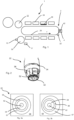
- Fig.1 shows a schematic representation of a device 1 according to the invention for heating plastic preforms 1.
- This device has a separating device such as a single-cycle star 30, which separates the plastic preforms that are fed in series by means of a feeding device 17 and feeds these separated plastic preforms 10 to a transport device 2.
- a separating device such as a single-cycle star 30, which separates the plastic preforms that are fed in series by means of a feeding device 17 and feeds these separated plastic preforms 10 to a transport device 2.
- the transport device 2 transports the plastic preforms 10 along a transport path T.
- This transport path T has two straight sections which are connected by a deflection region.
- the reference number 20 refers to a circulating transport means, such as in particular a transport chain.
- a plurality of holding devices 22 for holding the plastic preforms are arranged on this transport means.
- the reference number 24 designates a heating device such as a heating box, which is arranged stationary along the transport path T.
- This heating device has a plurality of heating radiators 26, which preferably extend along the transport path T, wherein preferably a plurality of heating radiators 22 are arranged one above the other in the longitudinal direction of the plastic preforms to be heated.
- the reference numeral 12 designates a further transport device which transports away the heated plastic preforms 10.
- the reference number 4 designates an inspection device which serves to inspect the holding devices 22 which are not occupied by plastic preforms. This can be done, for example, outside of a working mode of the device 1 in which no plastic preforms are arranged on the holding devices 22.
- This inspection device 4 preferably has an image recording device which records images of the holding devices 22. This image recording device is in particular a camera.
- the inspection device is shown here in the deflection area of the transport path T, in which the direction of movement of the plastic preforms is reversed.
- the image recording device 42 is preferably arranged below the holding devices.
- the image recording device could also be arranged laterally next to the transport path T and image recording could be made possible with deflection means such as mirrors.
- the device 1 preferably has an assignment device (not shown) which assigns recorded images to those holding devices 22 by which the images were recorded.
- Fig. 2 shows a representation of a holding device 22. This has a (lower) end face 32, which is preferably inspected by the inspection device.
- the reference number 52 designates a fastening means, which preferably fastens the individual elements of the holding device to one another.
- the reference number 36 designates clamping means, such as projections pushed radially outwards, which serve to hold the plastic preforms.
- the reference number 34 designates a flexible circumferential element, such as an O-ring.
- the Fig. 3a and 3b show two images of a holding device.
- the fastening means 52 can be seen again, which is located in the center of the holding device 22.
- the reference number 54 designates a front surface which is used in particular for observation or inspection. This front surface can have a special coating which facilitates observation or image evaluation.
- the reference number 56 designates an outer wall of the holding device. This outer wall 56, the fastening means 52 and the end face 54 are preferably concentric with one another. These elements can therefore be used to detect the concentricity or to determine an eccentricity.
- the reference number 58 designates a shielding plate which serves to prevent the mouths of the plastic preforms from heating up too much.
- a circumferential gap 57 is formed between the shielding device 58 and the outer wall.
- Fig. 3a shows a proper holding device. It can be seen that the fastening means, the front surface 45 and the outer wall 56 are concentric with the circumferential gap. The holding device is therefore concentrically aligned and therefore correct.
- the holding device 22 shown in the figure is eccentric.
- the front surface of the holding device 22 is offset slightly to the left compared to its nominal position. This means that the Fig. 3b
- the holding device 22 shown is faulty.
- the Fig. 3a and 3b The images taken are preferably compared with reference images, where such a reference image can, for example, show a proper holding device.
- the device 1 preferably also has an evaluation device which is suitable and intended to evaluate the recorded images.
- the evaluation device is preferably also suitable and intended to output a value which is characteristic of a certain eccentricity.
- This value can be assigned to a specific holding device. Depending on Depending on this value, different measures can be initiated.
Landscapes
- Physics & Mathematics (AREA)
- Thermal Sciences (AREA)
- Engineering & Computer Science (AREA)
- Manufacturing & Machinery (AREA)
- Mechanical Engineering (AREA)
- Health & Medical Sciences (AREA)
- Oral & Maxillofacial Surgery (AREA)
- Blow-Moulding Or Thermoforming Of Plastics Or The Like (AREA)
Applications Claiming Priority (1)
| Application Number | Priority Date | Filing Date | Title |
|---|---|---|---|
| DE102023106894.6A DE102023106894A1 (de) | 2023-03-20 | 2023-03-20 | Vorrichtung und Verfahren zum Erwärmen von Kunststoffvorformlingen mit Inspektion der Halteeinrichtungen |
Publications (2)
| Publication Number | Publication Date |
|---|---|
| EP4434718A2 true EP4434718A2 (fr) | 2024-09-25 |
| EP4434718A3 EP4434718A3 (fr) | 2024-11-06 |
Family
ID=90123829
Family Applications (1)
| Application Number | Title | Priority Date | Filing Date |
|---|---|---|---|
| EP24160980.9A Pending EP4434718A3 (fr) | 2023-03-20 | 2024-03-01 | Dispositif et procédé de chauffage d'ébauches en plastique avec inspection des dispositifs de retenue |
Country Status (4)
| Country | Link |
|---|---|
| US (1) | US20240316832A1 (fr) |
| EP (1) | EP4434718A3 (fr) |
| CN (1) | CN222610402U (fr) |
| DE (1) | DE102023106894A1 (fr) |
Family Cites Families (5)
| Publication number | Priority date | Publication date | Assignee | Title |
|---|---|---|---|---|
| DE19914028C1 (de) * | 1999-03-27 | 2000-09-21 | Krones Ag | Verfahren und Vorrichtung zur Inspektion von Hohlkörpern aus Kunststoff |
| DE102015122003A1 (de) * | 2015-12-16 | 2017-06-22 | Krones Ag | Vorrichtung und Verfahren zum Behandeln von Behältnissen mit Überwachung von Antriebsmotoren |
| JP7010294B2 (ja) * | 2017-08-28 | 2022-02-10 | Agc株式会社 | 積層体およびその製造方法 |
| DE102020123163A1 (de) * | 2020-09-04 | 2022-03-10 | Krones Aktiengesellschaft | Vorrichtung und Verfahren zum Erwärmen von Kunststoffvorformlingen mit ortaufgelöster Temperaturerfassung |
| FR3117921B1 (fr) * | 2020-12-22 | 2022-12-16 | Sidel Participations | Procédé de vérification automatique de la présence d'organes de maintien de préformes dans une station de chauffage |
-
2023
- 2023-03-20 DE DE102023106894.6A patent/DE102023106894A1/de active Pending
-
2024
- 2024-03-01 EP EP24160980.9A patent/EP4434718A3/fr active Pending
- 2024-03-19 CN CN202420538268.XU patent/CN222610402U/zh active Active
- 2024-03-20 US US18/611,397 patent/US20240316832A1/en active Pending
Also Published As
| Publication number | Publication date |
|---|---|
| CN222610402U (zh) | 2025-03-14 |
| EP4434718A3 (fr) | 2024-11-06 |
| DE102023106894A1 (de) | 2024-09-26 |
| US20240316832A1 (en) | 2024-09-26 |
Similar Documents
| Publication | Publication Date | Title |
|---|---|---|
| DE60103703T2 (de) | Automatisierte Steuerung der Materialverteilung in einem Streckblasgeformten Gegenstand | |
| EP3964348B1 (fr) | Dispositif et procédé de chauffage de préformes en matière plastique à détection de température à résolution espace | |
| EP2188108B2 (fr) | Procédé de moulage par soufflage de récipients | |
| EP2759829A1 (fr) | Installation de fabrication pour la fabrication de récipients à partir d'ébauches de récipients et procédé de fabrication | |
| EP3964349B1 (fr) | Dispositif et procédé de chauffage de préformes en matière plastique à détection de température à résolution espace | |
| DE202018106385U1 (de) | Vorrichtung zum Erwärmen von Kunststoffvorformlingen | |
| DE19821105A1 (de) | Vorrichtung und Verfahren zur Herstellung von Kunststoffhohlkörpern | |
| EP3630448B1 (fr) | Dispositif et procede de traitement de recipients avec un dispositif d'inspection optique | |
| EP4201637A1 (fr) | Dispositif et procédé de fabrication de récipients en plastique dotés de sections transversales non circulaires | |
| DE4332024C2 (de) | Verfahren zur Steuerung der freien Verformung von thermoplastischem Material | |
| EP4434718A2 (fr) | Dispositif et procédé de chauffage d'ébauches en plastique avec inspection des dispositifs de retenue | |
| EP4245503A1 (fr) | Procédé et dispositif de fabrication de récipients en matière plastique à section non circulaire | |
| EP3928954B1 (fr) | Dispositif et procédé de chauffage des préformes en matière plastique comportant un dispositif de mise au point réglable | |
| DE102018128143A1 (de) | Vorrichtung und Verfahren zum Erwärmen von Kunststoffvorformlingen | |
| DE102018130639A1 (de) | Vorrichtung zum Erwärmen von Kunststoffvorformlingen mit Abschirmplatte für Wärmestrahlungen | |
| EP4265391A1 (fr) | Dispositif et procédé de fabrication de récipients en plastique dotés de sections transversales non circulaires | |
| EP4209326A2 (fr) | Dispositif et procédé de fabrication de récipients en plastique dotés de sections transversales non circulaires | |
| DE102016117870A1 (de) | Verfahren und Vorrichtung zum Herstellen von Behältnissen | |
| EP4563325B1 (fr) | Dispositif de contrôle pour contrôler au moins une préforme, machine d'étirage-soufflage et procédé de contrôle d'une préforme | |
| EP4269066B1 (fr) | Procédé de chauffage et dispositif de chauffage pour le conditionnement thermique de préformes, ainsi que machine de fabrication de récipients pour le formage de préformes avec un dispositif de chauffage | |
| DE102023114882A1 (de) | Vorrichtung und Verfahren zum Herstellen von Kunststoffbehältnissen mit von einem kreisförmigen Querschnitt abweichenden Querschnitt | |
| EP4585396A1 (fr) | Dispositif et procédé de fabrication d'ébauches en plastique dotées d'un dispositif de capture d'image infrarouge | |
| EP4585393A1 (fr) | Dispositif et procédé de fabrication de récipients en plastique avec inspection de préformes en plastique | |
| EP4585397A2 (fr) | Dispositif et procédé de traitement d'ébauches en plastique à l'aide d'une détection de température | |
| EP4585394A1 (fr) | Dispositif et procédé de fabrication d'ébauches en plastique au moyen d'un dispositif d'analyse spectrale |
Legal Events
| Date | Code | Title | Description |
|---|---|---|---|
| PUAI | Public reference made under article 153(3) epc to a published international application that has entered the european phase |
Free format text: ORIGINAL CODE: 0009012 |
|
| STAA | Information on the status of an ep patent application or granted ep patent |
Free format text: STATUS: THE APPLICATION HAS BEEN PUBLISHED |
|
| AK | Designated contracting states |
Kind code of ref document: A2 Designated state(s): AL AT BE BG CH CY CZ DE DK EE ES FI FR GB GR HR HU IE IS IT LI LT LU LV MC ME MK MT NL NO PL PT RO RS SE SI SK SM TR |
|
| PUAL | Search report despatched |
Free format text: ORIGINAL CODE: 0009013 |
|
| AK | Designated contracting states |
Kind code of ref document: A3 Designated state(s): AL AT BE BG CH CY CZ DE DK EE ES FI FR GB GR HR HU IE IS IT LI LT LU LV MC ME MK MT NL NO PL PT RO RS SE SI SK SM TR |
|
| RIC1 | Information provided on ipc code assigned before grant |
Ipc: B29L 31/00 20060101ALN20241003BHEP Ipc: B29C 49/42 20060101ALN20241003BHEP Ipc: B29C 49/36 20060101ALN20241003BHEP Ipc: B29C 49/06 20060101ALN20241003BHEP Ipc: B29C 49/12 20060101ALN20241003BHEP Ipc: B29C 49/78 20060101ALI20241003BHEP Ipc: B29C 49/68 20060101AFI20241003BHEP |
|
| STAA | Information on the status of an ep patent application or granted ep patent |
Free format text: STATUS: REQUEST FOR EXAMINATION WAS MADE |
|
| 17P | Request for examination filed |
Effective date: 20250429 |