EP4434801A1 - Elektrisches strassenfahrzeug mit einer einzigen kühleinheit für ein batteriepack und eine leistungselektronik - Google Patents
Elektrisches strassenfahrzeug mit einer einzigen kühleinheit für ein batteriepack und eine leistungselektronik Download PDFInfo
- Publication number
- EP4434801A1 EP4434801A1 EP24164424.4A EP24164424A EP4434801A1 EP 4434801 A1 EP4434801 A1 EP 4434801A1 EP 24164424 A EP24164424 A EP 24164424A EP 4434801 A1 EP4434801 A1 EP 4434801A1
- Authority
- EP
- European Patent Office
- Prior art keywords
- battery pack
- vehicle
- electric
- road vehicle
- power
- Prior art date
- Legal status (The legal status is an assumption and is not a legal conclusion. Google has not performed a legal analysis and makes no representation as to the accuracy of the status listed.)
- Pending
Links
Images





Classifications
-
- B—PERFORMING OPERATIONS; TRANSPORTING
- B60—VEHICLES IN GENERAL
- B60L—PROPULSION OF ELECTRICALLY-PROPELLED VEHICLES; SUPPLYING ELECTRIC POWER FOR AUXILIARY EQUIPMENT OF ELECTRICALLY-PROPELLED VEHICLES; ELECTRODYNAMIC BRAKE SYSTEMS FOR VEHICLES IN GENERAL; MAGNETIC SUSPENSION OR LEVITATION FOR VEHICLES; MONITORING OPERATING VARIABLES OF ELECTRICALLY-PROPELLED VEHICLES; ELECTRIC SAFETY DEVICES FOR ELECTRICALLY-PROPELLED VEHICLES
- B60L50/00—Electric propulsion with power supplied within the vehicle
- B60L50/50—Electric propulsion with power supplied within the vehicle using propulsion power supplied by batteries or fuel cells
- B60L50/60—Electric propulsion with power supplied within the vehicle using propulsion power supplied by batteries or fuel cells using power supplied by batteries
- B60L50/66—Arrangements of batteries
-
- B—PERFORMING OPERATIONS; TRANSPORTING
- B60—VEHICLES IN GENERAL
- B60L—PROPULSION OF ELECTRICALLY-PROPELLED VEHICLES; SUPPLYING ELECTRIC POWER FOR AUXILIARY EQUIPMENT OF ELECTRICALLY-PROPELLED VEHICLES; ELECTRODYNAMIC BRAKE SYSTEMS FOR VEHICLES IN GENERAL; MAGNETIC SUSPENSION OR LEVITATION FOR VEHICLES; MONITORING OPERATING VARIABLES OF ELECTRICALLY-PROPELLED VEHICLES; ELECTRIC SAFETY DEVICES FOR ELECTRICALLY-PROPELLED VEHICLES
- B60L58/00—Methods or circuit arrangements for monitoring or controlling batteries or fuel cells, specially adapted for electric vehicles
- B60L58/10—Methods or circuit arrangements for monitoring or controlling batteries or fuel cells, specially adapted for electric vehicles for monitoring or controlling batteries
- B60L58/24—Methods or circuit arrangements for monitoring or controlling batteries or fuel cells, specially adapted for electric vehicles for monitoring or controlling batteries for controlling the temperature of batteries
- B60L58/26—Methods or circuit arrangements for monitoring or controlling batteries or fuel cells, specially adapted for electric vehicles for monitoring or controlling batteries for controlling the temperature of batteries by cooling
-
- B—PERFORMING OPERATIONS; TRANSPORTING
- B60—VEHICLES IN GENERAL
- B60H—ARRANGEMENTS OF HEATING, COOLING, VENTILATING OR OTHER AIR-TREATING DEVICES SPECIALLY ADAPTED FOR PASSENGER OR GOODS SPACES OF VEHICLES
- B60H1/00—Heating, cooling or ventilating devices
- B60H1/00271—HVAC devices specially adapted for particular vehicle parts or components and being connected to the vehicle HVAC unit
- B60H1/00278—HVAC devices specially adapted for particular vehicle parts or components and being connected to the vehicle HVAC unit for the battery
-
- B—PERFORMING OPERATIONS; TRANSPORTING
- B60—VEHICLES IN GENERAL
- B60H—ARRANGEMENTS OF HEATING, COOLING, VENTILATING OR OTHER AIR-TREATING DEVICES SPECIALLY ADAPTED FOR PASSENGER OR GOODS SPACES OF VEHICLES
- B60H1/00—Heating, cooling or ventilating devices
- B60H1/00357—Air-conditioning arrangements specially adapted for particular vehicles
- B60H1/00385—Air-conditioning arrangements specially adapted for particular vehicles for vehicles having an electrical drive, e.g. hybrid or fuel cell
- B60H1/00392—Air-conditioning arrangements specially adapted for particular vehicles for vehicles having an electrical drive, e.g. hybrid or fuel cell for electric vehicles having only electric drive means
-
- B—PERFORMING OPERATIONS; TRANSPORTING
- B60—VEHICLES IN GENERAL
- B60K—ARRANGEMENT OR MOUNTING OF PROPULSION UNITS OR OF TRANSMISSIONS IN VEHICLES; ARRANGEMENT OR MOUNTING OF PLURAL DIVERSE PRIME-MOVERS IN VEHICLES; AUXILIARY DRIVES FOR VEHICLES; INSTRUMENTATION OR DASHBOARDS FOR VEHICLES; ARRANGEMENTS IN CONNECTION WITH COOLING, AIR INTAKE, GAS EXHAUST OR FUEL SUPPLY OF PROPULSION UNITS IN VEHICLES
- B60K1/00—Arrangement or mounting of electrical propulsion units
- B60K1/04—Arrangement or mounting of electrical propulsion units of the electric storage means for propulsion
-
- B—PERFORMING OPERATIONS; TRANSPORTING
- B60—VEHICLES IN GENERAL
- B60K—ARRANGEMENT OR MOUNTING OF PROPULSION UNITS OR OF TRANSMISSIONS IN VEHICLES; ARRANGEMENT OR MOUNTING OF PLURAL DIVERSE PRIME-MOVERS IN VEHICLES; AUXILIARY DRIVES FOR VEHICLES; INSTRUMENTATION OR DASHBOARDS FOR VEHICLES; ARRANGEMENTS IN CONNECTION WITH COOLING, AIR INTAKE, GAS EXHAUST OR FUEL SUPPLY OF PROPULSION UNITS IN VEHICLES
- B60K1/00—Arrangement or mounting of electrical propulsion units
-
- B—PERFORMING OPERATIONS; TRANSPORTING
- B60—VEHICLES IN GENERAL
- B60K—ARRANGEMENT OR MOUNTING OF PROPULSION UNITS OR OF TRANSMISSIONS IN VEHICLES; ARRANGEMENT OR MOUNTING OF PLURAL DIVERSE PRIME-MOVERS IN VEHICLES; AUXILIARY DRIVES FOR VEHICLES; INSTRUMENTATION OR DASHBOARDS FOR VEHICLES; ARRANGEMENTS IN CONNECTION WITH COOLING, AIR INTAKE, GAS EXHAUST OR FUEL SUPPLY OF PROPULSION UNITS IN VEHICLES
- B60K1/00—Arrangement or mounting of electrical propulsion units
- B60K1/02—Arrangement or mounting of electrical propulsion units comprising more than one electric motor
-
- B—PERFORMING OPERATIONS; TRANSPORTING
- B60—VEHICLES IN GENERAL
- B60K—ARRANGEMENT OR MOUNTING OF PROPULSION UNITS OR OF TRANSMISSIONS IN VEHICLES; ARRANGEMENT OR MOUNTING OF PLURAL DIVERSE PRIME-MOVERS IN VEHICLES; AUXILIARY DRIVES FOR VEHICLES; INSTRUMENTATION OR DASHBOARDS FOR VEHICLES; ARRANGEMENTS IN CONNECTION WITH COOLING, AIR INTAKE, GAS EXHAUST OR FUEL SUPPLY OF PROPULSION UNITS IN VEHICLES
- B60K1/00—Arrangement or mounting of electrical propulsion units
- B60K2001/003—Arrangement or mounting of electrical propulsion units with means for cooling the electrical propulsion units
- B60K2001/005—Arrangement or mounting of electrical propulsion units with means for cooling the electrical propulsion units the electric storage means
-
- B—PERFORMING OPERATIONS; TRANSPORTING
- B60—VEHICLES IN GENERAL
- B60K—ARRANGEMENT OR MOUNTING OF PROPULSION UNITS OR OF TRANSMISSIONS IN VEHICLES; ARRANGEMENT OR MOUNTING OF PLURAL DIVERSE PRIME-MOVERS IN VEHICLES; AUXILIARY DRIVES FOR VEHICLES; INSTRUMENTATION OR DASHBOARDS FOR VEHICLES; ARRANGEMENTS IN CONNECTION WITH COOLING, AIR INTAKE, GAS EXHAUST OR FUEL SUPPLY OF PROPULSION UNITS IN VEHICLES
- B60K1/00—Arrangement or mounting of electrical propulsion units
- B60K1/04—Arrangement or mounting of electrical propulsion units of the electric storage means for propulsion
- B60K2001/0405—Arrangement or mounting of electrical propulsion units of the electric storage means for propulsion characterised by their position
-
- B—PERFORMING OPERATIONS; TRANSPORTING
- B60—VEHICLES IN GENERAL
- B60K—ARRANGEMENT OR MOUNTING OF PROPULSION UNITS OR OF TRANSMISSIONS IN VEHICLES; ARRANGEMENT OR MOUNTING OF PLURAL DIVERSE PRIME-MOVERS IN VEHICLES; AUXILIARY DRIVES FOR VEHICLES; INSTRUMENTATION OR DASHBOARDS FOR VEHICLES; ARRANGEMENTS IN CONNECTION WITH COOLING, AIR INTAKE, GAS EXHAUST OR FUEL SUPPLY OF PROPULSION UNITS IN VEHICLES
- B60K1/00—Arrangement or mounting of electrical propulsion units
- B60K1/04—Arrangement or mounting of electrical propulsion units of the electric storage means for propulsion
- B60K2001/0405—Arrangement or mounting of electrical propulsion units of the electric storage means for propulsion characterised by their position
- B60K2001/0416—Arrangement in the rear part of the vehicle
-
- B—PERFORMING OPERATIONS; TRANSPORTING
- B60—VEHICLES IN GENERAL
- B60L—PROPULSION OF ELECTRICALLY-PROPELLED VEHICLES; SUPPLYING ELECTRIC POWER FOR AUXILIARY EQUIPMENT OF ELECTRICALLY-PROPELLED VEHICLES; ELECTRODYNAMIC BRAKE SYSTEMS FOR VEHICLES IN GENERAL; MAGNETIC SUSPENSION OR LEVITATION FOR VEHICLES; MONITORING OPERATING VARIABLES OF ELECTRICALLY-PROPELLED VEHICLES; ELECTRIC SAFETY DEVICES FOR ELECTRICALLY-PROPELLED VEHICLES
- B60L2240/00—Control parameters of input or output; Target parameters
- B60L2240/40—Drive Train control parameters
- B60L2240/52—Drive Train control parameters related to converters
- B60L2240/525—Temperature of converter or components thereof
-
- B—PERFORMING OPERATIONS; TRANSPORTING
- B60—VEHICLES IN GENERAL
- B60L—PROPULSION OF ELECTRICALLY-PROPELLED VEHICLES; SUPPLYING ELECTRIC POWER FOR AUXILIARY EQUIPMENT OF ELECTRICALLY-PROPELLED VEHICLES; ELECTRODYNAMIC BRAKE SYSTEMS FOR VEHICLES IN GENERAL; MAGNETIC SUSPENSION OR LEVITATION FOR VEHICLES; MONITORING OPERATING VARIABLES OF ELECTRICALLY-PROPELLED VEHICLES; ELECTRIC SAFETY DEVICES FOR ELECTRICALLY-PROPELLED VEHICLES
- B60L2240/00—Control parameters of input or output; Target parameters
- B60L2240/40—Drive Train control parameters
- B60L2240/54—Drive Train control parameters related to batteries
- B60L2240/545—Temperature
Definitions
- the invention relates to power storage systems for the automotive industry and it relates to a vehicular battery pack and to a relative assembling method.
- the invention can advantageously, though not exclusively be applied to high-performance electric or hybrid road vehicles, to which explicit reference will be made in the description below without because of this lacking generality.
- Lithium batteries thanks to their high energy density, allow electric drive systems to be more and more implemented in the automotive industry.
- Lithium polymers in particular, currently represent, from an electrochemical point of view, the state of the art in the production of high-capacity batteries.
- vehicular battery packs which mainly comprise cylindrical or planar (prismatic or pouch) batteries.
- the battery pack of an electric vehicle needs to be cooled in order to maintain the cells within an ideal working range and reduce the deterioration thereof.
- gas for example, Freon
- air or liquid such as water or cooling liquid
- an electric motor vehicle typically needs electric devices that absorb or supply a significant or at least non-negligible amount of electric power, thus emanating heat during their operation.
- Heat determines an increase in the temperature of the electric devices, which include the battery pack, the electric motor and possible electric power converters.
- the temperature increase if uncontrolled, can cause an overheating of the aforesaid devices, which, in turn, can cause faults or even compromise the devices themselves.
- the temperature increase determines a drawback associated with a consequent increase in the electrical resistance of the aforesaid devices, corresponding, in turn, to a further increase in temperature and emanated heat.
- the concept of superconductivity that would be observed at 0°K gets farther.
- the emanated heat is usually dissipated by means of a plurality of cooling apparatuses distributed on board the road vehicle so as to cool the drives of the electric machines, the power electronics thereof and the batteries, in case high temperatures are reached.
- the Joule effect determining the generation of said heat is a source of energy losses, which result in a greater consumption of energy supplied by the vehicular battery pack (hence, in a reduction of performances).
- the cooling apparatuses available all over the vehicle usually comprise a refrigerator assembly, a heat exchanger and a hydraulic circuit in thermal contact with the electric devices emanating heat.
- the refrigerator assembly supplies the additional heat exchanger with an evaporating fluid so as to subtract heat from the liquid flowing in the hydraulic circuit.
- the liquid cooled by so doing in the area of the heat exchanger keeps flowing along the hydraulic circuit, thus reaching respective areas of exchange of heat with the electric devices distributed all over the road vehicle, where the liquid absorbs the heat emanated by the electric devices, hence lowering the temperature thereof.
- known cooling apparatuses need to be improved in order to cool the electric devices to a greater extent, thus decreasing the electrical resistance thereof and establishing, as a consequence, a virtuous cycle, in which the quantity of heat to be dissipated decreases, just like the waste of energy and the space needed for an effective operation of the cooling devices.
- the weight, the dimensions and the cost of known cooling devices need to be reduced, especially in high-performance vehicles, where these properties are particularly important.
- An object of the invention is to fulfil at least one of the needs discussed above, preferably in a simple and reliable fashion.
- the object of the invention is to provide a road vehicle, which is at least partially free from the drawbacks described above and, at the same time, is simple and economic to be manufactured.
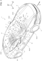
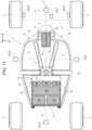
- number 1 indicates, as a whole, a road vehicle provided with two front wheels 2 and two rear wheels 3, at least a pair (or all) of them receiving the torque from a powertrain system 4.
- the road vehicle 1 is an at least partially electric vehicle (in particular, a full electric vehicle).
- the powertrain system 4 is an electric system (namely, it solely comprises one or more electric motors).
- second component does not imply the presence of a "first” component.
- these terms are only used as labels to improve clarity and should not be interpreted in a limiting manner.
- the road vehicle 1 further comprises a body 5 defining a passenger compartment 6, which is configured to accommodate at least a driver and, if necessary, one or more passengers.
- the passenger compartment 6 defines at least one cockpit 7 for the driver.
- the road vehicle 1 comprises a know vehicular frame, which is not described in detail and supports the body 5.
- the powertrain system 4 comprises at least one first electric machine 8, which is configured to control the motion of the drive wheels 2, 3.
- the road vehicle 1 comprises a vehicular battery pack 9 fitted to the frame and arranged so as to define at least part of a floorboard 10 of the road vehicle 1.
- the vehicular battery pack 9 is configured to power (for example, at 400 V or 800 V) at least the first electric machine 8.
- the battery pack 9 powers, through power converters (for example, DC-DC power converters), a large part of, if not all the other electric utilities of the road vehicle 1.
- power converters for example, DC-DC power converters
- the vehicular battery pack 9 comprises a support structure 11 extending along the vehicular longitudinal axis X and comprising a floor 12, which at least partly defines the floorboard of the road vehicle 1.
- the floor 12 substantially extends between a front axle (which is known and is not shown herein) and a rear axle (which is also known and is not shown herein) of the road vehicle 1.
- the floor 12 has a sheet-like shape (namely, it is shaped like a slab, with a thickness that is significantly smaller than the other two dimensions) comprising an inner surface 13 and an outer surface 14, which is opposite the inner surface 13 and is configured to face outwards so as to face the ground G.
- the battery pack 9 further comprises cylindrical, pouch or planar electrochemical cells of the known kind, which, therefore, will not be described in detail below, are electrically connected to one another and are arranged in the area of an outer surface 13.
- the floor 12 has a constant thickness.
- the vehicle 1 further comprises a cooling system 15 configured to cool at least the vehicular battery pack 9.
- the cooling system 15 can be centralized, hence, configured to generically cool the battery pack, or modular, so that each module of the battery pack is cooled by a dedicated sub-system. In this way, an ideal work temperature is ensured for the electrochemical cells of the battery pack, thus slowing down the degradation thereof and increasing their average life.
- the cooling system 15 involves the use of Freon, thus improving the exchange of heat.
- the vehicle 1 comprises power electronics circuitry 16, which is electrically interposed between the vehicular battery pack 9 and the first electric machine 8 and is configured to at least control the supply of electric power to at least the first electric machine 8.
- Said circuitry 16 (commonly known as inverter), in use, can reach significant temperatures (up to several hundred degrees), which have to be held under control by effectively and correctly dissipating the heat generated through Joule effect.
- the circuitry 16 is subjected to an increase in its electrical resistance and, hence, delivers a smaller power to the first electric machine 8 (since the passage of current is limited).
- the vehicle 1 advantageously comprises a refrigerated unit 17, which is cooled by the cooling system 15 and comprises, in turn, a box-shaped case 18 defining a housing 19, which is thermally insulated from the rest of the road vehicle 1.
- the case 18 is made of a plastic or composite material (to improve the mechanical performances thereof).
- Thermally insulated means, for the purposes of this disclosure, that the housing 19 is not affected by temperature changes on the outside of the case 18.
- the case 18 has a thermal conductivity of 0.3 to 3 W ⁇ m -1 ⁇ K -1 . Preferably less than 1 W ⁇ m -1 ⁇ K -1 .
- the case 18 is shaped so as to close itself on the battery pack 9, in particular on the edge of the floor 12.
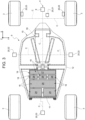
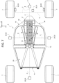
- the housing 19 advantageously accommodates, on the inside and preferably next to one another, both the vehicular battery pack 9 and the power electronics circuitry 16.
- the refrigerated unit 17 eliminates the need for a cooling device distributed along the entire vehicle 1, which, on the contrary, is necessary in the prior art.
- the road vehicle 1 further comprises one or more second electric machines 20. Therefore, the battery pack 9 is configured to also power said one or more second electric machines 20 and the power electronics circuitry (16) is electrically interposed between the vehicular battery pack 9 and said one or more second electric machines 20.
- said one or more second electric machines 20 comprise an air conditioning device 21 for the passenger compartment 6 and/or one or more electric motors 22 for vehicular comfort (for example, motors for moving the windows, the seats, the wipers, active suspensions, etc.) and/or one or more electronic safety systems 23, in particular, but not only, for managing the battery pack 9 (for example, fans, fuses, brake assist systems, ABS, self-driving systems, etc.).
- an air conditioning device 21 for the passenger compartment 6 and/or one or more electric motors 22 for vehicular comfort (for example, motors for moving the windows, the seats, the wipers, active suspensions, etc.) and/or one or more electronic safety systems 23, in particular, but not only, for managing the battery pack 9 (for example, fans, fuses, brake assist systems, ABS, self-driving systems, etc.).
- the power electronics circuitry 16 comprises one or more electric drives 24 for the first electric machine 8 and/or said one or more second electrical machines 20.
- the power electronics circuitry 16 comprises electronic power converters 25 (for example, DC-DC converters, but not in a limiting manner).
- the power electronics circuitry 16 comprises processors 26 or computer boards 27 (for example, video boards for support to driving or self-driving).
- only power and/or signal wiring C branches off from the case 18 towards the first electric machine 8 and/or towards the second electric machines 20.
- the cooling system 15 could also be used to cool air to be injected into the passenger compartment through the device 21.
- a dedicated air duct would come out of the case 18.
- electric machine identifies, for the purposes of this disclosure, an electric utility, not necessarily an electric motor.
- the cooling system 15 is preferably configured to maintain, on the inside of the refrigerated unit 17, a temperature below 15°C, in particular below 10°C, more in particular below 5°C. This leads to an improvement in the performances of processors and microprocessors, in particular of the electronic power converters 25 and/or of the processors 26 and/or of the computer boards 27 (for example, video boards for support to driving or self-driving).
- the power electronics circuitry 16 is supported by the vehicular battery pack 9, more in particular it is arranged above the vehicular battery pack 9.
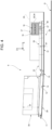
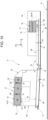
- the battery pack 9, in particular the floor 12, comprises, along the longitudinal axis X, a front portion 28 substantially parallel to the ground G and a rear portion 29 diverging from the ground G along a direction contrary to the normal travel direction D of the road vehicle.
- the portions 28 and 29 are both planar.
- the box-shaped case 18 is located in the area of the front portion 28 (as shown in the embodiments of figures 4 to 7 ).
- the box-shaped case 18 is located in the area of the rear portion 29, thus defining one or two housings 19 for the electronic circuitry 16.
- the battery pack 9 preferably comprises a verticalized portion 30 supported by the rear portion 29 and having a greater thickness W' than the rest of the battery pack 9.
- a first portion 31 of the housing 18 is located at the top of the verticalized portion 30.
- the first portion 31 of the housing 18 has the shape of a parallelepiped with a rectangular base, in particular whose cross section along a vertical plane ZX (namely, the plane on which axes Z and X lie) going through the longitudinal axis X of the road vehicle 1 is a parallelogram, because of the inclination relative to the ground G of the rear portion 29, whereas it has a rectangular cross section on plane ZY (namely, the plane on which axes Z and Y lie).
- the vertical character of the verticalized portion 25 significantly expands the capacity of the battery pack 9.
- the first portion 31 of the housing 18 has the shape of a parallelepiped with a rectangular base, in particular whose cross section along the vertical plane ZX going through the longitudinal axis X of the road vehicle 1 is a right-angled trapezoid having the oblique side 32 facing the passenger compartment 6 of the road vehicle 1, so as to improve the coupling to the front seats of the road vehicle 1.
- the battery pack 9 further comprises a lowered portion 33 supported by the front portion 28 and having a smaller thickness W" than the rest of the battery pack, in particular than the verticalized portion 30.
- a second portion 34 of the housing 18 is located at the top of the lowered portion 33.
- the second portion 34 of the housing 18 extends along the central longitudinal axis X of the road vehicle 1, under a central tunnel 35 of the road vehicle 1 (namely, the hollow longitudinal element generally interposed between the cockpit 7 and a possible passenger's seat).
- the power electronics circuitry 16 is connected to (powered by) the vehicular battery pack 9 through rigid connections 36, for example direct connectors between the different elements of the circuitry 16 or between each element and the battery pack 9, or - preferably - through busbars 37.
- rigid connections 36 for example direct connectors between the different elements of the circuitry 16 or between each element and the battery pack 9, or - preferably - through busbars 37.
- the aforesaid temperatures inside the case 18 also improve the performances of the busbars 37, thus improving the conductivity thereof.
- the battery pack 9 is arranged at the bottom of the passenger compartment 6.
- the front portion 28 is arranged under the cockpit 7 and the possible passenger's seat beside it, whereas the rear portion 29 is arranged behind the seats contained inside the passenger compartment 6.
- the battery pack 9 comprises at least one section configured to house a battery management system - BMS designed to control the operating parameters electrochemical cells.
- the case 18 comprises, on the inside, a first portion and a second portion, which is different from the first portion.
- the first portion and the second portion are adjacent to one another.
- the cooling system 15 is configured to keep the battery pack 9 (in the first portion) at a higher first temperature than the power electronic circuitry 16 (in the second portion, at a second temperature).
- this feature allows both the processors 26 and the battery pack 9 to operate at the respective ideal temperatures.
- the difference between the first and the second temperature is obtained by placing the power electronics circuitry 16 closer to the cooling system 15 (for example, to cooling panels thereof located in an upper portion of the case 18) than the battery pack 9, which, for example, is arranged under the circuitry 16.
- the battery pack 9 is kept at a higher temperature by means of suitable protective layers.
- the invention offers many advantages.
- the refrigerated unit includes, on the inside, all the components to be cooled.
- the invention improves cooling efficiency, by properly sizing one single local cooling system, which is already present for cooling the battery pack.
- a further advantage of the invention lies in the simplicity of installation of the refrigerated unit by means of rigid connectors, which simplify the assembly thereof, reduce the possibility of errors and the quantity of material used, hence the weight.
- the invention allows for a more effective cooling compared to prior art, with the consequent establishment of a virtuous cycle in which the power electronics circuitry generates less and less heat thanks to lower and lower temperatures, thus reducing the quantity of cooling fluid needed for the conditioning to a greater and greater extent, allowing for the use of smaller connectors thanks to the greater conductivity, reducing weights and improving the management of volumes and performances.
Landscapes
- Engineering & Computer Science (AREA)
- Mechanical Engineering (AREA)
- Transportation (AREA)
- Life Sciences & Earth Sciences (AREA)
- Sustainable Development (AREA)
- Sustainable Energy (AREA)
- Power Engineering (AREA)
- Physics & Mathematics (AREA)
- Thermal Sciences (AREA)
- Chemical & Material Sciences (AREA)
- Combustion & Propulsion (AREA)
- Arrangement Or Mounting Of Propulsion Units For Vehicles (AREA)
Applications Claiming Priority (1)
| Application Number | Priority Date | Filing Date | Title |
|---|---|---|---|
| IT102023000005280A IT202300005280A1 (it) | 2023-03-21 | 2023-03-21 | Veicolo stradale ibrido o elettrico con unita' refrigerata unica per pacco batteria e elettronica di potenza |
Publications (1)
| Publication Number | Publication Date |
|---|---|
| EP4434801A1 true EP4434801A1 (de) | 2024-09-25 |
Family
ID=86657266
Family Applications (1)
| Application Number | Title | Priority Date | Filing Date |
|---|---|---|---|
| EP24164424.4A Pending EP4434801A1 (de) | 2023-03-21 | 2024-03-19 | Elektrisches strassenfahrzeug mit einer einzigen kühleinheit für ein batteriepack und eine leistungselektronik |
Country Status (3)
| Country | Link |
|---|---|
| US (1) | US20240317112A1 (de) |
| EP (1) | EP4434801A1 (de) |
| IT (1) | IT202300005280A1 (de) |
Cited By (1)
| Publication number | Priority date | Publication date | Assignee | Title |
|---|---|---|---|---|
| US20240140272A1 (en) * | 2021-03-01 | 2024-05-02 | Elonroad Ab | A housing for a sunken electric road track, a sunken electric road track and a method for arranging a sunken electric road track along a road |
Citations (4)
| Publication number | Priority date | Publication date | Assignee | Title |
|---|---|---|---|---|
| US20060090877A1 (en) * | 2001-05-10 | 2006-05-04 | Honda Giken Kogyo Kabushiki Kaisha | Cooling structure for high tension electrical equipment |
| US9895981B2 (en) * | 2014-06-17 | 2018-02-20 | Ferrari S.P.A. | Electric power system of a vehicle with electric propulsion |
| US10314210B2 (en) * | 2016-07-26 | 2019-06-04 | Subaru Corporation | Electrical unit including battery and inverter with cooling |
| US20200207424A1 (en) * | 2018-12-27 | 2020-07-02 | Ferrari S.P.A. | Electric or hybrid sport car |
Family Cites Families (3)
| Publication number | Priority date | Publication date | Assignee | Title |
|---|---|---|---|---|
| JP7433748B2 (ja) * | 2018-05-31 | 2024-02-20 | 矢崎総業株式会社 | 給電ユニット |
| US12397684B2 (en) * | 2021-04-28 | 2025-08-26 | Dana Heavy Vehicle Systems Group, Llc | Electric powertrain and method for operation of said powertrain |
| US12194827B2 (en) * | 2022-07-07 | 2025-01-14 | GM Global Technology Operations LLC | Integrated electrified propulsion system for a vehicle |
-
2023
- 2023-03-21 IT IT102023000005280A patent/IT202300005280A1/it unknown
-
2024
- 2024-03-19 US US18/609,143 patent/US20240317112A1/en active Pending
- 2024-03-19 EP EP24164424.4A patent/EP4434801A1/de active Pending
Patent Citations (4)
| Publication number | Priority date | Publication date | Assignee | Title |
|---|---|---|---|---|
| US20060090877A1 (en) * | 2001-05-10 | 2006-05-04 | Honda Giken Kogyo Kabushiki Kaisha | Cooling structure for high tension electrical equipment |
| US9895981B2 (en) * | 2014-06-17 | 2018-02-20 | Ferrari S.P.A. | Electric power system of a vehicle with electric propulsion |
| US10314210B2 (en) * | 2016-07-26 | 2019-06-04 | Subaru Corporation | Electrical unit including battery and inverter with cooling |
| US20200207424A1 (en) * | 2018-12-27 | 2020-07-02 | Ferrari S.P.A. | Electric or hybrid sport car |
Cited By (1)
| Publication number | Priority date | Publication date | Assignee | Title |
|---|---|---|---|---|
| US20240140272A1 (en) * | 2021-03-01 | 2024-05-02 | Elonroad Ab | A housing for a sunken electric road track, a sunken electric road track and a method for arranging a sunken electric road track along a road |
Also Published As
| Publication number | Publication date |
|---|---|
| US20240317112A1 (en) | 2024-09-26 |
| IT202300005280A1 (it) | 2024-09-21 |
Similar Documents
| Publication | Publication Date | Title |
|---|---|---|
| US10978755B2 (en) | Cooling plate for a rechargeable energy storage system | |
| CN102456937B (zh) | 电池模块及组件 | |
| CN114174108B (zh) | 车辆用冷却装置 | |
| US12355047B2 (en) | Battery device for a motor vehicle, motor vehicle and method for operating a battery device | |
| US11228070B2 (en) | Efficient electric architectural layouts for electrified vehicles | |
| EP2494647B1 (de) | Kühlsystem für ein elektrogerät | |
| JP2011198688A (ja) | 車両用電池トレーおよびこれを備えた車両用電池装置 | |
| CN105552477A (zh) | 牵引电池的热管理 | |
| CN210167414U (zh) | 用于车辆的动力电池及具有其的车辆 | |
| EP4434801A1 (de) | Elektrisches strassenfahrzeug mit einer einzigen kühleinheit für ein batteriepack und eine leistungselektronik | |
| JP2020040578A (ja) | 車両 | |
| CN103118889B (zh) | 轮毂电动机型电动汽车 | |
| JP2024172114A (ja) | 車両駆動装置 | |
| CN116552643B (zh) | 电动载货车底盘和电动载货车 | |
| US20250167332A1 (en) | Vehicular battery pack and related road vehicle | |
| CN121097280A (zh) | 用于牵引电池包的多层热障总成 | |
| JP2022014897A (ja) | 自動車用の走行用バッテリーシステム及び電気駆動装置を有する自動車 | |
| US12597831B2 (en) | Cooling system for an electric traction machine for a motor vehicle | |
| US20240120806A1 (en) | Cooling system for an electric traction machine for a motor vehicle | |
| US20240322347A1 (en) | Vehicular battery pack and related assembly method | |
| US20250364633A1 (en) | Battery pack for an electric vehicle | |
| CN218400713U (zh) | 底盘结构及电动车辆 | |
| CN217532992U (zh) | 商用车底盘结构及作业机械 | |
| CN117042384A (zh) | 用于电动车辆的部件的热能管理系统和方法 | |
| US20260112734A1 (en) | Battery pack housing having plate assembly with air passages and fins |
Legal Events
| Date | Code | Title | Description |
|---|---|---|---|
| PUAI | Public reference made under article 153(3) epc to a published international application that has entered the european phase |
Free format text: ORIGINAL CODE: 0009012 |
|
| STAA | Information on the status of an ep patent application or granted ep patent |
Free format text: STATUS: THE APPLICATION HAS BEEN PUBLISHED |
|
| AK | Designated contracting states |
Kind code of ref document: A1 Designated state(s): AL AT BE BG CH CY CZ DE DK EE ES FI FR GB GR HR HU IE IS IT LI LT LU LV MC ME MK MT NL NO PL PT RO RS SE SI SK SM TR |
|
| STAA | Information on the status of an ep patent application or granted ep patent |
Free format text: STATUS: REQUEST FOR EXAMINATION WAS MADE |
|
| 17P | Request for examination filed |
Effective date: 20250325 |