EP4434837A1 - Interface utilisateur pour la perception situationnelle d'un conducteur - Google Patents
Interface utilisateur pour la perception situationnelle d'un conducteur Download PDFInfo
- Publication number
- EP4434837A1 EP4434837A1 EP23172588.8A EP23172588A EP4434837A1 EP 4434837 A1 EP4434837 A1 EP 4434837A1 EP 23172588 A EP23172588 A EP 23172588A EP 4434837 A1 EP4434837 A1 EP 4434837A1
- Authority
- EP
- European Patent Office
- Prior art keywords
- driver
- vehicle
- collision
- ttc
- threats
- Prior art date
- Legal status (The legal status is an assumption and is not a legal conclusion. Google has not performed a legal analysis and makes no representation as to the accuracy of the status listed.)
- Withdrawn
Links
Images




Classifications
-
- B—PERFORMING OPERATIONS; TRANSPORTING
- B60—VEHICLES IN GENERAL
- B60W—CONJOINT CONTROL OF VEHICLE SUB-UNITS OF DIFFERENT TYPE OR DIFFERENT FUNCTION; CONTROL SYSTEMS SPECIALLY ADAPTED FOR HYBRID VEHICLES; ROAD VEHICLE DRIVE CONTROL SYSTEMS FOR PURPOSES NOT RELATED TO THE CONTROL OF A PARTICULAR SUB-UNIT
- B60W30/00—Purposes of road vehicle drive control systems not related to the control of a particular sub-unit, e.g. of systems using conjoint control of vehicle sub-units
- B60W30/08—Active safety systems predicting or avoiding probable or impending collision or attempting to minimise its consequences
- B60W30/09—Taking automatic action to avoid collision, e.g. braking and steering
-
- B—PERFORMING OPERATIONS; TRANSPORTING
- B60—VEHICLES IN GENERAL
- B60K—ARRANGEMENT OR MOUNTING OF PROPULSION UNITS OR OF TRANSMISSIONS IN VEHICLES; ARRANGEMENT OR MOUNTING OF PLURAL DIVERSE PRIME-MOVERS IN VEHICLES; AUXILIARY DRIVES FOR VEHICLES; INSTRUMENTATION OR DASHBOARDS FOR VEHICLES; ARRANGEMENTS IN CONNECTION WITH COOLING, AIR INTAKE, GAS EXHAUST OR FUEL SUPPLY OF PROPULSION UNITS IN VEHICLES
- B60K35/00—Instruments specially adapted for vehicles; Arrangement of instruments in or on vehicles
- B60K35/20—Output arrangements, i.e. from vehicle to user, associated with vehicle functions or specially adapted therefor
- B60K35/28—Output arrangements, i.e. from vehicle to user, associated with vehicle functions or specially adapted therefor characterised by the type of the output information, e.g. video entertainment or vehicle dynamics information; characterised by the purpose of the output information, e.g. for attracting the attention of the driver
-
- B—PERFORMING OPERATIONS; TRANSPORTING
- B60—VEHICLES IN GENERAL
- B60K—ARRANGEMENT OR MOUNTING OF PROPULSION UNITS OR OF TRANSMISSIONS IN VEHICLES; ARRANGEMENT OR MOUNTING OF PLURAL DIVERSE PRIME-MOVERS IN VEHICLES; AUXILIARY DRIVES FOR VEHICLES; INSTRUMENTATION OR DASHBOARDS FOR VEHICLES; ARRANGEMENTS IN CONNECTION WITH COOLING, AIR INTAKE, GAS EXHAUST OR FUEL SUPPLY OF PROPULSION UNITS IN VEHICLES
- B60K35/00—Instruments specially adapted for vehicles; Arrangement of instruments in or on vehicles
- B60K35/20—Output arrangements, i.e. from vehicle to user, associated with vehicle functions or specially adapted therefor
- B60K35/29—Instruments characterised by the way in which information is handled, e.g. showing information on plural displays or prioritising information according to driving conditions
-
- B—PERFORMING OPERATIONS; TRANSPORTING
- B60—VEHICLES IN GENERAL
- B60W—CONJOINT CONTROL OF VEHICLE SUB-UNITS OF DIFFERENT TYPE OR DIFFERENT FUNCTION; CONTROL SYSTEMS SPECIALLY ADAPTED FOR HYBRID VEHICLES; ROAD VEHICLE DRIVE CONTROL SYSTEMS FOR PURPOSES NOT RELATED TO THE CONTROL OF A PARTICULAR SUB-UNIT
- B60W30/00—Purposes of road vehicle drive control systems not related to the control of a particular sub-unit, e.g. of systems using conjoint control of vehicle sub-units
- B60W30/08—Active safety systems predicting or avoiding probable or impending collision or attempting to minimise its consequences
- B60W30/095—Predicting travel path or likelihood of collision
- B60W30/0953—Predicting travel path or likelihood of collision the prediction being responsive to vehicle dynamic parameters
-
- B—PERFORMING OPERATIONS; TRANSPORTING
- B60—VEHICLES IN GENERAL
- B60W—CONJOINT CONTROL OF VEHICLE SUB-UNITS OF DIFFERENT TYPE OR DIFFERENT FUNCTION; CONTROL SYSTEMS SPECIALLY ADAPTED FOR HYBRID VEHICLES; ROAD VEHICLE DRIVE CONTROL SYSTEMS FOR PURPOSES NOT RELATED TO THE CONTROL OF A PARTICULAR SUB-UNIT
- B60W30/00—Purposes of road vehicle drive control systems not related to the control of a particular sub-unit, e.g. of systems using conjoint control of vehicle sub-units
- B60W30/08—Active safety systems predicting or avoiding probable or impending collision or attempting to minimise its consequences
- B60W30/095—Predicting travel path or likelihood of collision
- B60W30/0956—Predicting travel path or likelihood of collision the prediction being responsive to traffic or environmental parameters
-
- B—PERFORMING OPERATIONS; TRANSPORTING
- B60—VEHICLES IN GENERAL
- B60W—CONJOINT CONTROL OF VEHICLE SUB-UNITS OF DIFFERENT TYPE OR DIFFERENT FUNCTION; CONTROL SYSTEMS SPECIALLY ADAPTED FOR HYBRID VEHICLES; ROAD VEHICLE DRIVE CONTROL SYSTEMS FOR PURPOSES NOT RELATED TO THE CONTROL OF A PARTICULAR SUB-UNIT
- B60W50/00—Details of control systems for road vehicle drive control not related to the control of a particular sub-unit, e.g. process diagnostic or vehicle driver interfaces
- B60W50/08—Interaction between the driver and the control system
- B60W50/14—Means for informing the driver, warning the driver or prompting a driver intervention
-
- B—PERFORMING OPERATIONS; TRANSPORTING
- B60—VEHICLES IN GENERAL
- B60W—CONJOINT CONTROL OF VEHICLE SUB-UNITS OF DIFFERENT TYPE OR DIFFERENT FUNCTION; CONTROL SYSTEMS SPECIALLY ADAPTED FOR HYBRID VEHICLES; ROAD VEHICLE DRIVE CONTROL SYSTEMS FOR PURPOSES NOT RELATED TO THE CONTROL OF A PARTICULAR SUB-UNIT
- B60W50/00—Details of control systems for road vehicle drive control not related to the control of a particular sub-unit, e.g. process diagnostic or vehicle driver interfaces
- B60W50/08—Interaction between the driver and the control system
- B60W50/14—Means for informing the driver, warning the driver or prompting a driver intervention
- B60W50/16—Tactile feedback to the driver, e.g. vibration or force feedback to the driver on the steering wheel or the accelerator pedal
-
- B—PERFORMING OPERATIONS; TRANSPORTING
- B60—VEHICLES IN GENERAL
- B60K—ARRANGEMENT OR MOUNTING OF PROPULSION UNITS OR OF TRANSMISSIONS IN VEHICLES; ARRANGEMENT OR MOUNTING OF PLURAL DIVERSE PRIME-MOVERS IN VEHICLES; AUXILIARY DRIVES FOR VEHICLES; INSTRUMENTATION OR DASHBOARDS FOR VEHICLES; ARRANGEMENTS IN CONNECTION WITH COOLING, AIR INTAKE, GAS EXHAUST OR FUEL SUPPLY OF PROPULSION UNITS IN VEHICLES
- B60K2360/00—Indexing scheme associated with groups B60K35/00 or B60K37/00 relating to details of instruments or dashboards
- B60K2360/16—Type of output information
- B60K2360/178—Warnings
-
- B—PERFORMING OPERATIONS; TRANSPORTING
- B60—VEHICLES IN GENERAL
- B60K—ARRANGEMENT OR MOUNTING OF PROPULSION UNITS OR OF TRANSMISSIONS IN VEHICLES; ARRANGEMENT OR MOUNTING OF PLURAL DIVERSE PRIME-MOVERS IN VEHICLES; AUXILIARY DRIVES FOR VEHICLES; INSTRUMENTATION OR DASHBOARDS FOR VEHICLES; ARRANGEMENTS IN CONNECTION WITH COOLING, AIR INTAKE, GAS EXHAUST OR FUEL SUPPLY OF PROPULSION UNITS IN VEHICLES
- B60K2360/00—Indexing scheme associated with groups B60K35/00 or B60K37/00 relating to details of instruments or dashboards
- B60K2360/18—Information management
- B60K2360/188—Displaying information using colour changes
-
- B—PERFORMING OPERATIONS; TRANSPORTING
- B60—VEHICLES IN GENERAL
- B60W—CONJOINT CONTROL OF VEHICLE SUB-UNITS OF DIFFERENT TYPE OR DIFFERENT FUNCTION; CONTROL SYSTEMS SPECIALLY ADAPTED FOR HYBRID VEHICLES; ROAD VEHICLE DRIVE CONTROL SYSTEMS FOR PURPOSES NOT RELATED TO THE CONTROL OF A PARTICULAR SUB-UNIT
- B60W50/00—Details of control systems for road vehicle drive control not related to the control of a particular sub-unit, e.g. process diagnostic or vehicle driver interfaces
- B60W50/08—Interaction between the driver and the control system
- B60W50/14—Means for informing the driver, warning the driver or prompting a driver intervention
- B60W2050/143—Alarm means
-
- B—PERFORMING OPERATIONS; TRANSPORTING
- B60—VEHICLES IN GENERAL
- B60W—CONJOINT CONTROL OF VEHICLE SUB-UNITS OF DIFFERENT TYPE OR DIFFERENT FUNCTION; CONTROL SYSTEMS SPECIALLY ADAPTED FOR HYBRID VEHICLES; ROAD VEHICLE DRIVE CONTROL SYSTEMS FOR PURPOSES NOT RELATED TO THE CONTROL OF A PARTICULAR SUB-UNIT
- B60W50/00—Details of control systems for road vehicle drive control not related to the control of a particular sub-unit, e.g. process diagnostic or vehicle driver interfaces
- B60W50/08—Interaction between the driver and the control system
- B60W50/14—Means for informing the driver, warning the driver or prompting a driver intervention
- B60W2050/146—Display means
-
- B—PERFORMING OPERATIONS; TRANSPORTING
- B60—VEHICLES IN GENERAL
- B60W—CONJOINT CONTROL OF VEHICLE SUB-UNITS OF DIFFERENT TYPE OR DIFFERENT FUNCTION; CONTROL SYSTEMS SPECIALLY ADAPTED FOR HYBRID VEHICLES; ROAD VEHICLE DRIVE CONTROL SYSTEMS FOR PURPOSES NOT RELATED TO THE CONTROL OF A PARTICULAR SUB-UNIT
- B60W2540/00—Input parameters relating to occupants
- B60W2540/225—Direction of gaze
-
- B—PERFORMING OPERATIONS; TRANSPORTING
- B60—VEHICLES IN GENERAL
- B60W—CONJOINT CONTROL OF VEHICLE SUB-UNITS OF DIFFERENT TYPE OR DIFFERENT FUNCTION; CONTROL SYSTEMS SPECIALLY ADAPTED FOR HYBRID VEHICLES; ROAD VEHICLE DRIVE CONTROL SYSTEMS FOR PURPOSES NOT RELATED TO THE CONTROL OF A PARTICULAR SUB-UNIT
- B60W2554/00—Input parameters relating to objects
- B60W2554/40—Dynamic objects, e.g. animals, windblown objects
- B60W2554/404—Characteristics
- B60W2554/4041—Position
-
- B—PERFORMING OPERATIONS; TRANSPORTING
- B60—VEHICLES IN GENERAL
- B60W—CONJOINT CONTROL OF VEHICLE SUB-UNITS OF DIFFERENT TYPE OR DIFFERENT FUNCTION; CONTROL SYSTEMS SPECIALLY ADAPTED FOR HYBRID VEHICLES; ROAD VEHICLE DRIVE CONTROL SYSTEMS FOR PURPOSES NOT RELATED TO THE CONTROL OF A PARTICULAR SUB-UNIT
- B60W2556/00—Input parameters relating to data
- B60W2556/45—External transmission of data to or from the vehicle
- B60W2556/65—Data transmitted between vehicles
-
- B—PERFORMING OPERATIONS; TRANSPORTING
- B60—VEHICLES IN GENERAL
- B60W—CONJOINT CONTROL OF VEHICLE SUB-UNITS OF DIFFERENT TYPE OR DIFFERENT FUNCTION; CONTROL SYSTEMS SPECIALLY ADAPTED FOR HYBRID VEHICLES; ROAD VEHICLE DRIVE CONTROL SYSTEMS FOR PURPOSES NOT RELATED TO THE CONTROL OF A PARTICULAR SUB-UNIT
- B60W2756/00—Output or target parameters relating to data
- B60W2756/10—Involving external transmission of data to or from the vehicle
Definitions
- This document relates to a user interface for a driver of a vehicle.
- FCW Forward Collision Warning
- AEB Automatic Emergency Braking
- FCW Forward Collision Warning
- AEB Automatic Emergency Braking
- FCW outputs an emergency alert (e.g., a loud audible sound, bright or flashing visible cue, intense haptic feedback), which is a strong signal meant to elicit an immediate driver response to the emergency.
- an emergency alert e.g., a loud audible sound, bright or flashing visible cue, intense haptic feedback
- the AEB automatically overrides the vehicle controls to cause a sudden correction (e.g., hard-braking) to avoid the danger.
- FCW FCW only when a situation turns critical (e.g., when a collision is predicted near in range or time). This occurs when a final opportunity is predicted for a driver to control inputs for preventing a crash. If without driver correction, a collision prediction can still change and not result in a crash (e.g., when a collision is predicted far in range or time), then the FCW is suppressed. Without controlling the FCW to only intervene during critical situations, the ADAS may underperform and routinely output frequent false positives (e.g., low likelihood collision predictions). Numerous false alarms may distract or even overwhelm drivers, which may cause unsafe or uncomfortable driving.
- UI user interface
- HMI Human-Machine Interface
- the described techniques and systems output a user interface (UI), such as a Human-Machine Interface (HMI), to a driver of a vehicle.
- UI user interface
- HMI Human-Machine Interface
- the UI is output to include UI elements (e.g., audible, visual, and/or haptic) for informing the driver about collision threats to improve driver situational awareness and assess each collision risk.
- Variation in the UI elements is used to help drivers a greater awareness of potential threats to help them make safe driving decisions, without annoying or desensitizing the drivers with frequent false alarms that might otherwise distract drivers and reduce vehicle safety.
- the UI Rather than output strong warning signals to elicit an emergency driver response, the UI generates UI elements that provide early-warning reference indicators to potential threats relative to a vehicle path. A corresponding level of risk for each object is conveyed in the UI elements with subtle cues (e.g., audible, visual, and/or haptic feedback). For example, the UI elements are output through the UI using weaker magnitude signals than other signals output on the vehicle, e.g., for forward-collision or other emergency warnings. This subtlety in how risk is conveyed for each collision threat enables the UI and the UI elements to be effective at informing a driver, without alarming or distracting them. A driver that is more aware of potential dangers may drive with greater confidence and without fear of threats that may be hidden from the driver's view.
- subtle cues e.g., audible, visual, and/or haptic feedback
- the UI elements are output through the UI using weaker magnitude signals than other signals output on
- a method for indicating changes in severity of collision risks to driving includes obtaining information indicative of potential collision threats to objects detected near a travel path of a host vehicle.
- the information including a Time-To-Collision (TTC) parameter for each of the potential collision threats.
- TTC Time-To-Collision
- the method further includes determining, by at least one processor of a host vehicle, a corresponding collision risk level for each of the potential collision threats based on the TTC parameter obtained for that potential collision threat.
- the method further includes outputting, for assisting a driver of the host vehicle, a user interface including an arrangement of interface elements indicating a relative location along the travel path and the corresponding collision risk level determined for each of the potential collision threats.
- a processor of a vehicle or vehicle system may be configured to execute the above-summarized method, including in some cases by retrieving instructions for executing the method, which are stored on a computer-readable storage medium.
- UI User Interface
- An ADAS typically executes or interfaces with an object detection and/or tracking function on the vehicle to predict whether any objects in the environment pose critical safety threats sufficient for warning or intervening.
- the ADAS is configured to receive information from many sources to learn about the environment. The information is processed to correctly identify each critical situation and induce an appropriate driver or vehicle response that does not falsely alarm the driver to a non-emergency.
- a list of objects may be maintained with each object being associated with an assessed level of risk or estimated chance of causing a collision.
- UI User Interface
- UI User Interface
- UI elements of the driver interface When the UI elements of the driver interface are output, information they convey heightens a driver's understanding of an environment to improve driver awareness about collision risks, without annoying or surprising the driver to react at a last moment.
- an example UI can be output as part of a graphical user interface (GUI), audible interface, haptic feedback interface, or any combination thereof, which is perceivable to a driver.
- GUI graphical user interface
- the UI may be a Human-Machine Interface (HMI) (e.g., gauge cluster, heads up display) that is adapted to indicate relative markers associated with the objects being tracked in the environment. Two-dimensional representations of a vehicle point of view may be presented including three-dimensional object-models displayed relative their current position and heading at that time.
- the HMI may refrain from highlighting certain objects likely to pose no threat or that the driver is likely already aware of (e.g., from gaze detection analysis).
- the UI In operation, the UI generates an early-warning reference indicator (e.g., a reference map) with the reference markers to potential threats presented relative a host vehicle position and/or trajectory to inform the driver, during non-critical situations, about objects near a vehicle travel path.
- the markers may indicate relative position and movement of each object in comparison to a vehicle position and estimated trajectory.
- Each object reported in reference map is conveyed with subtle cues (e.g., audible, visual, and/or haptic feedback) that are much weaker signals than the strong signals output for emergency warnings. These subtle signals provided in the reference map are intended to inform, without alarming or distracting, the driver to be made more aware of potential dangers that may be partially hidden or obscured from a driver position.
- the UI is configured to inform a driver to help anticipate when critical situations may occur, which is different than traditional safety features that are designed to cause an emergency reaction.
- the UI conveys information about potential threats to improve driver awareness of potential threats, to help ease worry and not cause distraction.
- the UI outputs subtle signals to not annoy a driver who may already be driving cautiously or with a heightened awareness.
- the ADAS system can make the driver aware to objects are already being assessed by the ADAS system, but do not rise to the level of causing warnings.
- the techniques enable the driver to gain awareness about otherwise unforeseen circumstances, without adding complexity to an existing overall ADAS object detection or vehicle architecture. In this way, the driver is provided with extra information even more intelligently to elicit a positive response from having advanced notice about changing traffic situations, without being annoyed from presence of known obstacles.
- the UI may prevent delayed reactions caused by a driver that is surprised when a prediction suddenly changes to an imminent threat.
- Drivers may have more time to try to mitigate a situation before the FCW and/or AEB engages; this provides drivers more time to react before a situation becomes critical, without being inundated with numerous false alarms to collision predictions that are unlikely to occur.
- the information output from the UI elements can improve driving comfort and driving safety without hindering the effectiveness of emergency alerts in critical situations.
- FIG. 1 illustrates an environment 100 in which an example UI for driver situational awareness is used on a host vehicle.
- a vehicle 102 is driving along a roadway 104 with an object 106 (e.g., a pedestrian, a bicycle, another vehicle) located near or in the roadway 104, which is a potential collision threat, or in other words, current trajectories of the vehicle 102 and the object 106 indicate the vehicle 102 may collide or crash into the object 106.
- an object 106 e.g., a pedestrian, a bicycle, another vehicle
- the vehicle 102 can represent other types of motorized vehicles (e.g., a passenger truck, a car, a motorcycle, a bus, a tractor, a semi-trailer truck), watercraft (e.g., a boat), or aircraft (e.g., an airplane).
- motorized vehicles e.g., a passenger truck, a car, a motorcycle, a bus, a tractor, a semi-trailer truck
- watercraft e.g., a boat
- aircraft e.g., an airplane
- the vehicle 102 is a host vehicle in context of this disclosure.
- the vehicle 102 includes an Advanced Driving Assistance System (ADAS) 108 to help the driver avoid collisions including with the object 106.
- the ADAS 108 includes an emergency alarm system 110 and an emergency intervention system 112.
- the emergency alarm system 110 may be a Forward Collision Warning (FCW) safety feature configured to activate an emergency alarm onboard the vehicle 102 to warn the driver of the vehicle 102 that a driver reaction (e.g., hard braking) is recommended to avoid an impending collision.
- the emergency intervention system may be an Automatic Emergency Brake (AEB) safety feature configured to activate an emergency countermeasure to prevent collisions when a crash is imminent.
- AEB Automatic Emergency Brake
- the ADAS 108 may include one or more processors configured to obtain information indicative of potential collision threats from objects detected near a travel path of the vehicle 102.
- the vehicle 102 includes one or more object detectors, which are sensors or devices that generate reports of objects detected in the environment 100. Each sensor of the vehicle 102 generate sensor data (e.g., camera, lidar, radar, ultrasound).
- the ADAS 108 can obtain other information, such as V2X data including external observation data obtained from object detection devices installed in other vehicles or V2X infrastructure.
- the ADAS 108 infers position, trajectory, and other information (e.g., classification, size) based on the information obtained from these onboard and external object detectors to estimate a Time-To-Collision (TTC) for each of the potential threats.
- TTC Time-To-Collision
- a processor of the ADAS 108 can receive camera data, radar data, or any combination of various types of sensor data to increase perception capability of the ADAS 108 across a variety of driving conditions. For example, information about objects detected with a camera may be more reliable when a radar sensor field of view is obstructed by a guard rail. The radar information may be of higher value for predicting collision threats when weather or poor visibility is an issue for the camera and the driver.
- the ADAS 108 maintains TTC parameters associated with the obj ects detected in the environment 100 and outputs the TTC parameters and/or triggers activation of safety features on the vehicle 102 based on their values.
- the ADAS 108 may cause the emergency alarm system 110 to activate in response to the TTC parameter for any object being less than or equal to approximately one and one half seconds.
- This activation threshold for the emergency alarm system 110 may provide sufficient time for the driver of the vehicle 102 to immediately react with driver inputs to the vehicle 102 (e.g., hard force applied to the brake pedal, counter steering) to avoid a predicted collision ahead. If set too high output with a magnitude to notify and alarm the driver too early, the ADAS 108 may be annoying or even startle the driver and decrease safety.
- the ADAS 108 may cause the emergency intervention system 112 to activate in response.
- This emergency intervention system 112 is configured to activate (e.g., automatically causing corrective steer or maximum brake input to the vehicle controls) at a last predicted opportunity to avoid the collision despite the emergency alarm. Setting this threshold inaccurately (e.g., too high) can further induce driver annoyance or decrease safety.
- the vehicle 102 includes a driver awareness system 114, which may allow drivers to anticipate critical situations sooner than with reliance on these existing emergency features.
- the driver awareness system 114 provides a user interface (UI) system 116, which is also referred to as a driver interface 116, and a situational awareness manager 118.
- UI user interface
- the driver awareness system 114 may execute as part of the ADAS 108 or be performed from executing instructions on other processing circuitry or hardware on the vehicle 102.
- the UI system 116 is configured to output signals to a driver of the vehicle 102, which instead of causing surprise or annoyance may improve driver awareness.
- the signals output from the UI system 116 are user interface elements.
- the user interface elements are output with characteristics tuned to provide advanced notice of possible critical situations, which may in the future but do not presently require immediate driver reactions.
- Information output in the signals conveyed by the interface elements output from the UI system 116 may help the driver supervise the environment 100 before the emergency thresholds for warnings and/or intervention are triggered.
- the UI system 116 enables the vehicle 102 to improve driving safety by increasing possible reaction time for the driver to intervene before a situation turns critical. These subtle cues from the UI system 116 may greatly improve driving experiences with gained attention, which increases vehicle safety.
- the situational awareness manager 118 monitors information from the ADAS 108 to update the UI system 116 as the environment 100 changes and objects move in and out of a threat category. For instance, the situational awareness manager 118 receives information from the ADAS 108 indicating the TTC parameters associated with the potential collision threats predicted by the ADAS. The situational awareness manager 118 can maintain the potential collision threats in a list or other data store to keep track of each potential collision threat including an indication of criticality or chance of resulting in a vehicle crash.
- a TTC 120 exists between the vehicle 102 and the object 106. Overtime, the TTC 120 may decrease (as shown in the graph in FIG. 1 ) and change values from times T1 to T3. Based on the TTC parameter for each of the potential collision threats monitored and reported in the output from the ADAS 108, a corresponding collision risk level is selected and assigned by the situational awareness manager 118 for each of the potential collision threats.
- a low risk level before time T1 can be assigned to a collision threat when the TTC is high (e.g., greater than three or four seconds) to indicate less need to supervise the collision threat at the present time. For example, if the TTC 120 is greater than a reporting threshold, then the situational awareness manager 118 refrains from signaling about that potential collision threat through information conveyed in UI elements of the UI system 116. If the TTC 120 later decreases and eventually falls below or satisfies the reporting threshold, then a medium risk level 122 is assigned to that threat.
- the medium risk level 122 has a lower TTC value than the low risk threats (e.g., between one and a half and three or four seconds) and may be assigned to collision threats between times T1 and T2.
- the UI system 116 is configured to signal without alarming the driver to notice each of the potential collision threats that is of the medium risk level 122.
- the medium risk level 122 can be assigned a range of TTC values to give warning of a growing threat before the situation turns critical and the emergency warning is issued (e.g., set to an FCW threshold).
- the medium risk level 122 may be associated with a range of values of TTC parameters determined to be greater than an emergency threshold for triggering a collision warning to cause an audible alarm to be output separate from the user interface. That is, different vehicles can set the medium risk level 122 to encompass a larger or smaller range of TTC parameters leading up to a mandated emergency threshold, such as an FCW threshold and/or AEB threshold.
- a high risk level 124 can be assigned a shorter TTC threshold (e.g., less than one and one half seconds, less than one second), which corresponds to a TTC that is just outside the range of the medium risk level 122.
- the high risk level 124 is set to a TTC threshold meant to improve effectiveness of emergency alarms that are output from the emergency alarm system 110.
- the high risk level 124 may be associated with a range of values of TTC parameters determined to be between mandated emergency thresholds. That is, the high risk level 124 may be attributed to the TTC parameters determined to be between the emergency threshold (e.g., the FCW threshold) and an automatic intervention threshold for triggering an automated vehicle countermeasure to avoid the vehicle crash (e.g., the AEB threshold).
- a critical risk level 126 can be assigned a shortest TTC threshold, such that automatic intervention occurs when a situation is critical and the TTC nears zero (e.g., the TTC is less than one second) to enable the emergency intervention system 112 to mitigate the danger.
- the critical risk level 126 may be for the TTC parameters determined to be at or less than the automatic intervention threshold (e.g., the AEB threshold).
- the TTC threshold for the risk levels 122, 124, and 126 may be different depending on different safety regulations throughout the world. Some vehicle ADAS systems operate by triggering an FCW at one and a half seconds TTC, whereas in other vehicles, their ADAS systems may trigger the FCW at one point seven seconds TTC. Furthermore, the TTC threshold for the risk levels 122, 124, and 126 may be different depending on different driving conditions (e.g., different driving speeds). For example, the risk levels 122, 124, and 126 may be set to higher values when a vehicle drives at slow speeds and lower TTC values as the speed increases and reaction time needed for the driver or automatic intervention grows.
- the high risk level 124 associated with the FCW can be determined as an offset applied to the critical risk level 126 associated with the AEB. This offset may be approximately one and a quarter seconds.
- the high risk level 124 is set earlier than the AEB threshold to account for an estimated reaction time of the driver (e.g., around 1.2 seconds) to respond to an emergency alarm.
- the situational awareness manager 118 controls the UI system 116 to cause a driverawareness user interface to be output inside the vehicle 102, for assisting a driver of the vehicle 102.
- the UI system 116 can output the user interface on any display, surface, or with various types of visual, audible, and/or haptic feedback.
- a gauge cluster behind a steering wheel is often used to indicate current speed and navigation information to help drive.
- the information displayed in a clear (e.g., unobstructed) view of the driver can be modified to include information from the UI system 116 to provide additional driver assistance.
- the UI system 116 is configured to output, for presentation to the driver, an arrangement of UI elements (e.g., graphical elements, audible sounds, directed vibrations) for indicating to the driver about relative locations on the travel path where each of the collision threats is present. Also provided is an indication of a collision risk level corresponding to each threat, which is determined from a level assigned by the situational awareness manager 118.
- the UI elements output for displaying or otherwise conveying each of the collision threats can have a different color or size, variable frequency flash pattern, or other indication make identifying the level of risk easier to the driver. For example, green color can be used for a bounding box type graphical UI element to indicate a low risk collision threat, yellow for medium, and red for high risk. Varying intensity of the interface elements, such as sound (e.g., silent, quiet, loud) or vibration of audible or haptic type interface elements may be effective at indicating changes in severity or level of risk of each potential collision threat.
- the situational awareness manager 118 is responsible for updating the user interface output by the UI system 116.
- the ADAS 108 regularly updates the TTC associated with the collision threats. If an update to a TTC parameter indicates a change in risk associated with that collision, the situation awareness manager 118 controls the UI system 116 to modify a corresponding UI element representative of that threat. For example, the UI system 116 adjust the arrangement of UI elements for signaling the driver about any changes to the relative location or to the current level of collision risk selected and assigned based on the updated TTC. A larger size or more prominent color can be used for a bounding box (or other UI representation of the collision threat) to indicate a greater risk of collision threat, which may be effective at providing subtle notice and increasing driver awareness of the environment 100.
- the UI system 116 allows the emergency alarm system 110 and/or the emergency intervention system 112 to activate normally, as indicated above, to prevent a crash.
- the UI system 116 may improve effectiveness of the emergency alarm system 110 and/or the emergency intervention system 112 in preventing crashes more frequently because the driver is prepared for their alarms and sudden corrections even if they cannot react in time to drive safely on their own. For example, if the TTC parameters or updated TTC associated with any of the collision threats satisfies an emergency threshold, the ADAS 108 may activate a collision warning system for outputting an emergency interface for alarming the driver to avoid a collision. If that is not effective, the ADAS 108 may initiate an emergency brake function to cause a sudden stop.
- FIG. 2 illustrates an example driver view 200 from a host vehicle configured to provide an example UI for driver situational awareness.
- a driver 218 of the vehicle 102 may supervise an environment for safe driving by monitoring for objects that can appear in and out of a driver field of view 202 from behind a steering wheel 220.
- objects 206-1 to 206-n are visible near the roadway 104.
- infrastructure devices 208-1 to 208-m appear in view of the driver 218, including a traffic light 208-1, another traffic light 208-2, and a traffic camera 208-3.
- a vehicle 206-1 is stopped because of the traffic light 208-1, as a pedestrian 206-2 crosses an intersection in the roadway 104.
- Another vehicle 206-3 is exiting an intersection in the roadway 104 as another pedestrian 206-4 begins to cross.
- the pedestrian may not have right of way because the traffic light 208-2 is set to allow the vehicle 102 to proceed through the intersection at the same time the pedestrian 206-4 is crossing.
- Partially masked in the driver field of view 202 is a third vehicle 206-n.
- a building 210 or other structure prevents the driver 218 from seeing the third vehicle 206-n because of the obstruction.
- the pedestrian 206-4 may be difficult to notice in the field of view 202 because of the crossing vehicle 206-3.
- the driver 218 may recognize that the vehicle 206-3 is exiting the intersection, which is otherwise indicated as clear for travel based on a green light from the traffic light 208-2.
- the driver 218 may not anticipate that the pedestrian 206-4 is j-walking and react too slow to avoid a collision but for an emergency alarm and/or emergency intervention.
- the vehicle 102 provides a driver awareness user interface 204 to be able to assess whether to expect an emergency given relative positions and expected movements of the objects 206.
- the interface 204 includes a clear indication of the objects 206 and their assessed level of risk to causing a crash.
- the user interface 204 is shown as being located behind the steering wheel 220 of the vehicle 102 to include graphical UI elements arranged to appear similar to the relative locations of objects outside the vehicle 102.
- Other displays and feedback systems e.g., light bars, sound devices, haptic generators
- a heads-up display on the windshield may be used to augment the driver field of view 202 with graphical UI elements appearing on the windshield from regions where each object is visible to the driver.
- the user interface 204 is output, for assisting a driver of the host vehicle 102.
- the user interface 204 includes an arrangement of interface elements 212.
- the user interface 204 includes an arrangement of interface elements 212 (e.g., graphical elements 212-1 to 212-n) that are output for each potential collision threat from any of the detected objects 206.
- the interface elements 212 each indicate a relative location along the travel path and the corresponding collision risk level determined for each different potential collision threat.
- Graphical element 212-1 corresponds to the vehicle 206-1
- graphical element 212-2 corresponds to the pedestrian 206-2
- an obstruction 216 Further highlighted in the user interface 204 is an obstruction 216. The indication of the obstruction 216 may be output when objects in the environment 100 are present but are outside the view of the driver 218.
- the ADAS 108 may provide information to the situational awareness manager 118 about more objects than are visible from the field of view 202.
- the vehicle 102 may receive a message from the traffic camera 208-m indicating the object 206-n having traveled recently passed the intersection.
- the message may be a Vehicle-To-Everything (V2X) type message; and can arrive from the traffic lights 208-1, 208-2, or even the other vehicles 206-1, 206-3, and 206-4.
- V2X Vehicle-To-Everything
- a V2X message may be received from either source indicating the presence of objects otherwise obscured by the building 210.
- the situational awareness manager 118 may obtain information from the ADAS 108 indicative of potential collision threats to objects 106 detected near a travel path of the host vehicle 102.
- the information includes a TTC parameter for each of the potential collision threats, which the situational awareness manager 118 uses to determine a corresponding collision risk level for each of the potential collision threats. Each corresponding collision risk level is determined based on the TTC parameter obtained for that potential collision threat.
- the situational awareness manager 118 configures the user interface 204 to be updated based on new information from the ADAS 108 to indicate changes in TTC and/or level of criticality associated with the objects 206 so the driver 218 can be prepared to drive safely in the intersection.
- the interface elements 212 may be modified to indicate changes to the relative location or the corresponding collision risk level determined for each of the potential collision threats.
- the user interface 204 is updated by the user interface system 116 and/or from information obtained from the situational awareness manager 118 indicating changes in severity of potential collision risks to driving in the environment 100.
- FIG. 3 illustrates an example traffic situation 300 where an otherwise potential collision threat is mitigated with an example UI for driver situational awareness.
- the vehicle 102 is driving towards an intersection 304 at the same time the object 106 (e.g., a cyclist) is traveling on a bicycle path or sidewalk 302 towards the same intersection 304.
- the driver of the vehicle 102 only has a visible field of view 306, which does not capture the object 106.
- An obstruction 308 e.g., a building
- onboard sensors of the vehicle 102 may communicate to the ADAS 108 information about the object 106 captured by a sensor with a better view than the driver to detect the object 106 behind the obstruction 308.
- the obstruction 308 may be a hedge or fence; using a front radar or roof mounted camera on the vehicle 102, the onboard sensor may have an improved view of the potential collision threat because of a higher mounting position (e.g., sufficient to detect a bike helmet moving lateral to a top of a hedge).
- the driver awareness system 114 may receive information from the ADAS 108 about hidden objects that do not appear to the driver to be a current threat, and present that information to the driver to cause less annoyance and improve safety. For example, an indication of a moving bicycle that is highlighted a different color depending on its assessed level of collision risk to help the driver prepare for the intersection 304.
- FIG. 4 illustrates an example traffic situation 400 where another potential collision threat is mitigated with an example UI for driver situational awareness.
- V2X communication is used to track the object 106 while the object 106 is obstructed from onboard vehicle sensors (e.g., radar, camera) and/or the driver.
- V2X refers to communications between a vehicle and any entity that may affect, or may be affected by, the vehicle.
- V2X communication systems handle various more specific types of communication, such as, V2I (vehicle-to-infrastructure), V2N (vehicle-to-network), V2V (vehicle-to-vehicle), V2P (vehicle-to-pedestrian), and V2D (vehicle-to-device).
- V2I vehicle-to-infrastructure
- V2N vehicle-to-network
- V2V vehicle-to-vehicle
- V2P vehicle-to-pedestrian
- V2D vehicle-to-device
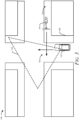
- the host vehicle 102 includes a radar with a line of sight 406-1 and a camera with a line of sight 406-2.
- the vehicle 102 is driving towards an intersection 404 shared by the roadway 104 and a bicycle path 402.
- Another vehicle 416 is driving towards the intersection 404 on a roadway adjacent to the bicycle path 402; the vehicle 416 has a sensor line of sight 418 and is tracking the object 106 using an onboard ADAS of the vehicle 416.
- the line of sight 406-1 and the line of sight 406-2 do not provide a view around an obstruction 408, therefore, the ADAS 108 on the vehicle 102 cannot detect any potential threat using onboard sensors.
- the UI system 116 is configured to output UI elements to provide information signaling the driver of the vehicle 102 about potential collision threats.
- the ADAS 108 can receive information about the object 106 to cause the UI system 116 to update the driver interface and cause the driver to be aware of the object 106 as the object approaches.
- the UI system 116 may first show an indication of the bicyclist, which the driver cannot see, and then highlight the indication as over time the driver is not slowing down enough to be prepared for the situation. In this way, the situational awareness manager 118 may determine at least part of the information indicative of the potential collision threats based on sensor data obtained from one or more sensors of the vehicle 102.
- the situational awareness manager 118 may further determine a remainder of the information indicative of the potential collision threats based on V2X data obtained from one or more external V2X devices remote to the vehicle 102. In this way, information about objects detected near the vehicle 102 can come from a variety of information sources, which pass through the ADAS 108, to enable accurate information to be presented by the UI system 116 for minimizing annoyance and increasing safety.
- the host vehicle 102 may generate V2X messages to enable a similar user interface to be generated quickly by another vehicle.
- V2X messages may be output from the vehicle 102, to a V2X receiver of another vehicle, to cause updates directly to another driverawareness user interface of that other vehicle.
- the V2X messages may include specific bits of data to flag an object of the message as being a potential threat for collision based on the observer point of view. Rather than process this specific message through traditional ADAS functions, another situational awareness manager on the remote vehicle can quickly make updates to the driver interface controlled on that vehicle. This may improve processing efficiency and performance of the systems and safety overall.
- the UI system 116 may update the user interface 204 and cause the driver to be aware of the object 106 as the object approaches in various ways.
- the interface elements 212 may be modified through changing a color, sound, or haptic signal of the interface elements 212 to indicate changes to the relative location or the corresponding collision risk level determined for each of the potential collision threats.
- rearranging or repositioning the interface elements 212 to be arranged differently within the arrangement in the user interface 204 can be effective to indicate change to the relative location of each of the potential collision threats.
- Varying color, brightness, volume, or amplitude of each signal conveyed with the interface elements 212 may indicate changes to the corresponding collision risk level determined for each of the potential collision threats. This way, more than one feature of the user interface elements output by the UI system 116 can be modified to convey updates to potential collision threats, using subtle signals that do not annoy or distract the driver.
- FIG. 5 illustrates an example process executed by a vehicle with a UI for driver awareness.
- the process 500 is shown as sets of operations (or acts) performed for indicating changes in severity of collision risks to driving; the process 500 is not necessarily limited to the order or combinations in which the operations are shown herein. Further, any one of one or more of the operations may be repeated, combined, or reorganized to provide other processes.
- reference may be made to the environment 100 and other elements described above in relation to FIGS. 1 through 4 . These references are to provide clarity and aid in understanding, and do not limit the techniques to performance by any specific one or more entities.
- step 502 information indicative of potential collision threats from objects detected near a travel path of a host vehicle is obtained.
- the ADAS 108 obtains information about the object 106 detected by another vehicle (e.g., with V2X) or based on sensor data from onboard camera, radar, lidar, or other sensing technology.
- the information includes the TTC parameters for each of the potential collision threats detected by the ADAS 108.
- a corresponding collision risk level for each of the potential collision threats based on the TTC parameter obtained for that potential collision threat is determined. That is, TTC parameters are monitored for the potential collision threats.
- the corresponding collision risk level for each of the potential collision threats may be determined to be one of a plurality of risk levels. Each of the risk levels being different and associated with a different range of TTC parameter values; each risk level indicates a different chance of resulting in a vehicle crash.
- the ADAS 108 may receive information about, or calculate directly, path predictions for the vehicle 102 and the object 106 and other objects tracked by the vehicle 102. If a potential intersection between paths is possible, then a potential collision threat is identified by the situational awareness manager 118; similar to performing a collision test for each object. As one example, consider at least three different risk levels used by the situational awareness manager 118. A first risk level for the TTC parameters is determined to be greater than an emergency threshold for triggering a collision warning to cause an audible alarm to be output separate from the user interface.
- the first risk level may include a range of TTC values that exceed the FCW threshold, but are not so far in time (e.g., not too large) such that their chance of causing a collision is likely to change.
- a second risk level for the TTC parameters may include a lower range of TTC values determined to be between the emergency threshold and an automatic intervention threshold for triggering an automated vehicle countermeasure to avoid the vehicle crash.
- the second risk level may include a range of TTC values that satisfy (e.g., are less than or equal to) the FCW threshold but are not yet critical and may still change if the driver reacts prior to the AEB being triggered with the AEB threshold being satisfied.
- a third risk level may encompass a range of values for the TTC parameters determined to be at or less than the automatic intervention threshold (e.g., the AEB threshold).
- a user interface is output for assisting a driver of the host vehicle by presenting an arrangement of interface elements for indicating a relative location along the travel path and a corresponding collision risk level determined for each of the potential collision threats.
- the situational awareness manager 118 may use a plurality of risk levels including one or more first risk levels indicating a lower chance (e.g., a minimal chance, a near zero or zero percent chance, less than a fifty-fifty chance) of that potential collision threat actually resulting in a vehicle crash.
- One or more second risk levels (e.g., a moderate chance, a greater than zero percent chance, near a fifty-fifty chance) indicating a greater chance of resulting in a vehicle crash may be between the first risk levels and a third risk level.
- the third risk level (e.g., a maximum chance, a near hundred percent chance, greater than a fifty-fifty chance) may indicate a vehicle crash is imminent.
- the first risk level is selected for a first range of TTC values that are each greater than a maximum threshold for monitoring the collision threats.
- the first range of TTC values may be greater than approximately two and one half seconds.
- the second risk level may be selected for a second range of TTC values that are between the maximum threshold for monitoring the collision threats and the emergency threshold.
- the second range of TTC values may be greater than approximately one and one half seconds.
- the third risk level is sometimes selected for a third range of TTC values that are between the emergency threshold and an automatic intervention threshold for activating an automated vehicle emergency countermeasure to avoid a vehicle crash.
- the third range of TTC values may be greater than approximately one second and the automatic intervention threshold is approximately one second.
- the TTC parameters or updated TTC associated with any of the collision threats satisfies an emergency threshold.
- the TTC for each of the objects is evaluated by the ADAS 108 to activate or refrain from activating safety features (e.g., emergency warnings, emergency interventions). This way existing safety features can operate with the user interface without error or interruption.
- step 508 whether a TTC of any object satisfies an automatic emergency intervention threshold is determined. This can occur before, during, or after outputting the user interface.
- an automated vehicle emergency countermeasure is activated to avoid a collision. For example, if the TTC falls to one second or less, then the ADAS 108 may engage a braking controller to stop the vehicle. The ADAS 108 may, if any of the updated TTC parameters satisfies the automatic intervention threshold (e.g., AEB threshold), activate, separate from the user interface 204, an automated vehicle countermeasure (e.g., AEB) to avoid the vehicle crash.
- the automatic intervention threshold e.g., AEB threshold
- step 512 if No is the result of step 508, then whether a TTC of any object satisfies an automatic emergency warning threshold is determined. This can occur before, during, or after outputting the user interface.
- step 514 if Yes is the result of step 512, an automated vehicle emergency warning is activated to cause a driver to react to avoid the collision. Otherwise, the process repeats and returns to step 502. For example, if the TTC falls to between one and one half seconds and one second, then the ADAS 108 may engage an emergency alarm to wake the driver to the situation. The ADAS 108 may activate, separate from what occurs with the user interface 204, if any of the updated TTC parameters satisfies the emergency threshold for causing a collision warning output (e.g., FCW) to include an audible alarm.
- a collision warning output e.g., FCW
- the user interface is configured to provide subtle indications of the degree of risk of collision, without alarming or annoying the driver.
- the step 506 is repeated to improve situational awareness for the driver as things in the environment change.
- the situational awareness manager 118 relies on other information to improve accuracy and usefulness of the UI system 116.
- a TTC of any object satisfies a driver awareness (DA) threshold is determined. For example, if the AEB threshold and the FCW thresholds are not satisfied, the situational awareness manager 118 determines whether any medium risk level collision threats exist.
- the UI system 116 is configured to highlight these medium threats to give the driver notice prior to a Yes determinations from step 508 or the step 512. For example, with TTC parameter values that exceed the AEB and FCW thresholds, the UI system 116 includes the interface elements 212 when the TTC parameter values are a few seconds in range of the thresholds used to activate other vehicle alarms and countermeasures. The UI system 116 takes care not to present the interface elements 212 to low risk collision threats. When a TTC parameter value is outside the DA threshold, the UI system 116 may refrain from outputting an indication of that potential collision threat, until the TTC parameter value approaches the emergency levels set for that vehicle.
- DA driver awareness
- the driver awareness interface is modified for enhancing output of signals to the driver to indicate relative locations of medium risk collision threats.
- the interface elements 212 may be modified to indicate changes to the relative location or the corresponding collision risk level determined for each of the potential collision threats.
- the user interface 204 may change over time to use different colors or properties in conveying the interface elements 212 corresponding to each threat. This may include changing a color, sound, or haptic signal of the interface elements 212 to indicate changes to the relative location or the corresponding collision risk level determined for each of the potential collision threats.
- Changing the arrangement of the interface elements 212 may further indicate updates to the potential collision threats. For example, changing positioning of the interface elements 212 within the arrangement shown in the user interface 204 indicates changes to their relative locations or their relative collision risk levels among all the potential collision threats.
- a modification to the interface elements 212 can occur if the TTC associated with that interface element causes the risk level to change and become more or less serious.
- all objects are presented in the driver interface and only medium or higher risk level threats are highlighted.
- each object is highlighted differently according to a corresponding risk level.
- the user interface may make medium and high risk threats have more prominent signals than low risk objects shown to convey where critical situations are more likely to occur.
- the gauze direction of the driver is determined.
- Information about driver gauze is obtained from interior sensors or from the ADAS 108 to indicate a direction of focus for the driver.
- the situational awareness manager 118 can include gaze direction as a factor in updating the user interface.
- the situational awareness manager 118 may determine a gauze direction of the driver and cause the UI system 116 to change a signal intensity for at least one of the interface elements 212 that is output in a region of the user interface 204 that is outside the gauze direction.
- the user interface 204 can cause certain interface elements 222 to have more prominence (e.g., greater brightness, louder sound, stronger haptics) to get a driver to notice the potential collision threat associated with the user interface elements 222 that are away from their gaze.
- the driver may be made more aware of the potential collision threats without being annoyed by an alarm or unexpected countermeasure.
- a corresponding UI element may be modified based on the gauze direction to increase the signaling (e.g., until the driver changes gauze), particularly when the object is outside the driver gauze.
- UI elements in the user interface can include changing a color or other property of a visible UI element (e.g., from a first color to a second color to increase the signaling).
- a tone associated with a UI element can be varied from a first volume to a second volume to increase the signaling; similarly, strength of a haptic feedback signal associated with a corresponding UI element may be changed from a first level to a second level to increase the signaling.
- FIG. 6 illustrates an example vehicle architecture 600 with a UI for driver awareness.
- the vehicle architecture 600 is for a vehicle 102-1 equipped with an ADAS 108-1, which is an example of the ADAS 108.
- a driver awareness system 114-1 is included in the vehicle 102-1.
- the ADAS 108-1 and the driver awareness system 114-1 may be part of a single or distributed system on the vehicle 102-1 and may interface with various components to execute functions.
- the vehicle 102-1 includes one or more exterior sensors 602, one or more interior sensors 604, one or more communication devices 606, one or more processors 608, one or more output devices 610, one or more input devices 612, and in some cases, one or more Vehicle-to-Everything (V2X) devices 616 and/or a driver gauze monitor 614, as well as computer-readable storage media (CRM) 618.
- the CRM 618 stores instructions associated with a UI system 116-1 and a situational awareness manager 118-1, which, respectively, are examples of the UI system 116 and the situational awareness manager 118.
- an object data store 620 configured to maintain a list or other collection of objects tracked by the ADAS 118-1 and their respective TTC parameters.
- the object data store 620 may be written directly by the ADAS 108-1 and/or indirectly updated by the situational awareness manager 118-1.
- the exterior sensors 602 and the interior sensors 604 may be mounted to, or integrated within, any portion of the vehicle 102 to provide an instrumented field of view.
- the exterior sensors 602 can include camera systems, radar systems, lidar systems, or ultrasonic systems to detect and track the object 106.
- the exterior sensors 602 can provide sensor data regarding the object 106, including tracking data for the object 106.
- the tracking data can, for example, indicate a relative position (e.g., range and lateral positioning), heading, or speed relative the vehicle 102.
- the vehicle 102 includes multiple types of exterior sensors 602, such as a radar system and a camera, which provide a larger instrument field-of-view or improved detection of objects 106.
- the interior sensors 604 are mounted to, or integrated within, an interior portion of the vehicle 102 to detect aspects of the driver and/or passengers.
- the interior sensors 604 can include a camera or radar system that captures images of the driver.
- the interior sensors 604 can be positioned to have a field-of-view that includes the driver's head.
- the interior sensors 604 can determine whether the driver is looking at the roadway 104, the object 106, or looking elsewhere.
- the communication devices 606 include any radio or transceiver configured to send or receive signals for a vehicle.
- the communication devices 606 can include telecommunication radios, satellite transceivers, and the like.
- Some of the exterior sensors 602 may be configured as the communication devices 606, and the V2X devices 616 can be a subset of the communication devices 606 on the vehicle.
- the processors 608 can be a microprocessor or a system-on-chip.
- the processors 608 can execute instructions stored in the CRM 618.
- the processor 608 can process sensor data from the exterior sensors 602 and the interior sensors 604 and determine characteristics (e.g., relative positioning, range, and predicted tracks) for the object 106.
- the processor 608 can then control the operation of the UI system 116-1 to focus the driver's attention on the object 106 and avoid potential collisions or unsafe driving.
- the processor 608 can control, based on data from the exterior sensors 602 and the interior sensors 604, the output devices 610 to display a graphical driver interface that flashes red to refocus the driver's attention on the roadway 104 and a relative position of the object 106.
- the output devices 610 include any device used in providing a UI on a vehicle.
- the output devices 610 include output devices configured to generate audible signals (e.g., sounds, tones), visual signals (e.g., graphical elements, light indicators), and/or haptic feedback signals (e.g., vibrations) to cause the driver to take notice of a potential collision threat.
- Examples of the output devices 610 include audio output devices (e.g., speakers), visual output devices (e.g., display, lightbar, gauge cluster, light indicator), and haptic-feedback devices (e.g., vibration device).
- the V2X devices 616 are configured to send or receive vehicle based communication messages from infrastructure devices, emergency alert systems, and other vehicles and devices to enhance and improve driving.
- Vehicle-to-vehicle and vehicle to infrastructure are subsets of the V2X standards and are examples of the V2X devices 616.
- Additional situation awareness can be obtained from V2X messages broadcast in the environment 100, which can enhance the information obtained by the ADAS for detecting objects.
- the processors 608 may cause the V2X devices to output V2X messages to a V2X receiver of another vehicle. These V2X messages, upon receipt by the other vehicle, cause a processor of the other vehicle to update interface elements output in a user interface for the driver of the other vehicle.
- the driver awareness module 114-1 can generate an indication of the other vehicle including a level of risk of collision associated with it so the driver can prepare to maneuver differently if necessary to avoid a collision.
- the ADAS 108-1 and/or a separate component shown as the driver gauze monitor 614 may measure direction and/or duration of gauze of the driver based on data output from the interior sensors 604.
- the direction of the driver's focus can be inferred from the gauze data to enhance threat advanced notice provided by the driver awareness system 114-1. For example, if the gauze of the driver is to the left, and a bicycle is approaching the travel path of the vehicle 102-1 from the right, an indication of the bicycle's approach may be output in the UI system 116-1 with increased prominence to make the driver aware of its presence. In this way, visual alerts regarding the bicycle can be adapted to the driver's attentiveness. As described in greater detail below, if the driver is distracted and not looking at the roadway 104, the driver awareness system 114-1 can flash a red light indicator on a display to regain the driver's attention towards a potential collision threat elsewhere on the roadway 104.
- Embodiment 1 A method for indicating changes in severity of collision risks to driving, the method comprising: obtaining information indicative of potential collision threats to objects detected near a travel path of a host vehicle, the information including a Time-To-Collision (TTC) parameter for each of the potential collision threats; determining, by at least one processor of a host vehicle, a corresponding collision risk level for each of the potential collision threats based on the TTC parameter obtained for that potential collision threat; and outputting, for assisting a driver of the host vehicle, a user interface including an arrangement of interface elements indicating a relative location along the travel path and the corresponding collision risk level determined for each of the potential collision threats.
- TTC Time-To-Collision
- Embodiment 2 The method of any other embodiment, wherein the corresponding collision risk level for each of the potential collision threats is determined to be one of a plurality of risk levels each indicating a different chance of resulting in a vehicle crash.
- Embodiment 3 The method of any other embodiment, wherein the risk levels include: at least one first risk level for TTC parameters determined to be greater than an emergency threshold for triggering a collision warning to cause an audible alarm to be output separate from the user interface; at least one second risk level for TTC parameters determined to be between the emergency threshold and an automatic intervention threshold for triggering an automated vehicle countermeasure to avoid the vehicle crash; and at least one third risk level for TTC parameters determined to be at or less than the automatic intervention threshold.
- Embodiment 4 The method of any other embodiment, further comprising: if any TTC parameters satisfies the emergency threshold, activating, separate from the user interface, a collision warning output to include an audible alarm.
- Embodiment 5 The method of any other embodiment, further comprising: if any TTC parameters satisfies the automatic intervention threshold, activating, separate from the user interface, an automated vehicle countermeasure to avoid the vehicle crash.
- Embodiment 6 The method of any other embodiment, wherein: the emergency threshold is approximately one and one half seconds; and the automatic intervention threshold is approximately one second.
- Embodiment 7 The method of any other embodiment, further comprising: modifying, based on updated TTC parameters obtained for each of the potential collision threats, the interface elements to indicate changes to the relative location or the corresponding collision risk level determined for each of the potential collision threats.
- Embodiment 8 The method of any other embodiment, wherein modifying the interface elements comprises: changing a color, sound, or haptic signal of the interface elements to indicate changes to the relative location or the corresponding collision risk level determined for each of the potential collision threats.
- Embodiment 9 The method of any other embodiment, wherein modifying the interface elements comprises: changing positioning of the interface elements within the arrangement to indicate changes to the relative location or the corresponding collision risk level determined for each of the potential collision threats.
- Embodiment 10 The method of any other embodiment, further comprising: determining a gauze direction of the driver; and changing a signal intensity for at least one of the interface elements that is output in a region of the user interface that is outside the gauze direction.
- Embodiment 11 The method of any other embodiment, further comprising: determining, based on sensor data obtained from one or more sensors of the host vehicle, at least part of the information indicative of the potential collision threats; and determining, based on vehicle to everything (V2X) data obtained from one or more external V2X devices remote to the host vehicle, a remainder of the information indicative of the potential collision threats.
- V2X vehicle to everything
- Embodiment 12 The method of any other embodiment, wherein the sensors of the host vehicle include one or more camera systems, lidar systems, radar systems, or ultrasonic systems, and the V2X data includes external observation data obtained from detection devices installed in other vehicles or V2X infrastructure.
- the sensors of the host vehicle include one or more camera systems, lidar systems, radar systems, or ultrasonic systems
- the V2X data includes external observation data obtained from detection devices installed in other vehicles or V2X infrastructure.
- Embodiment 13 The method of any other embodiment, further comprising: outputting, by the processor, V2X messages to a V2X receiver of another vehicle for updating one or more of the interface elements output for another driver of the other vehicle.
- Embodiment 14 A vehicle system comprising one or more processors configured to perform the method of any other embodiment.
- Embodiment 15 A computer-readable storage medium comprising computer-executable instructions that, when executed, cause a vehicle system to perform the method of any other embodiment.
- Embodiment 16 A system comprising means for performing the method of any other embodiment.
Landscapes
- Engineering & Computer Science (AREA)
- Transportation (AREA)
- Mechanical Engineering (AREA)
- Automation & Control Theory (AREA)
- Chemical & Material Sciences (AREA)
- Combustion & Propulsion (AREA)
- Human Computer Interaction (AREA)
- Traffic Control Systems (AREA)
Priority Applications (1)
| Application Number | Priority Date | Filing Date | Title |
|---|---|---|---|
| US18/596,874 US20240317253A1 (en) | 2023-03-24 | 2024-03-06 | User Interface For Driver Situational Awareness |
Applications Claiming Priority (1)
| Application Number | Priority Date | Filing Date | Title |
|---|---|---|---|
| US202363492025P | 2023-03-24 | 2023-03-24 |
Publications (1)
| Publication Number | Publication Date |
|---|---|
| EP4434837A1 true EP4434837A1 (fr) | 2024-09-25 |
Family
ID=86331128
Family Applications (1)
| Application Number | Title | Priority Date | Filing Date |
|---|---|---|---|
| EP23172588.8A Withdrawn EP4434837A1 (fr) | 2023-03-24 | 2023-05-10 | Interface utilisateur pour la perception situationnelle d'un conducteur |
Country Status (1)
| Country | Link |
|---|---|
| EP (1) | EP4434837A1 (fr) |
Cited By (1)
| Publication number | Priority date | Publication date | Assignee | Title |
|---|---|---|---|---|
| CN121573011A (zh) * | 2026-01-27 | 2026-02-27 | 吉林大学 | 自动驾驶车辆动态阈值控制方法与多阈值协同控制方法 |
Citations (5)
| Publication number | Priority date | Publication date | Assignee | Title |
|---|---|---|---|---|
| US20160264108A1 (en) * | 2015-03-13 | 2016-09-15 | Toyota Jidosha Kabushiki Kaisha | Collision avoidance apparatus |
| US20180101736A1 (en) * | 2016-10-11 | 2018-04-12 | Samsung Electronics Co., Ltd. | Method for providing a sight securing image to vehicle, electronic apparatus and computer readable recording medium therefor |
| US20180281788A1 (en) * | 2015-10-06 | 2018-10-04 | Hitachi, Ltd. | Automatic drive control device and automatic drive control method |
| US20200047668A1 (en) * | 2016-10-20 | 2020-02-13 | Panasonic Corporation | Pedestrian-vehicle communication system, in-vehicle terminal device, pedestrian terminal device and safe-driving assistance method |
| WO2021205430A1 (fr) * | 2020-04-06 | 2021-10-14 | Adam Cogtech Ltd. | Production et présentation de stimuli |
-
2023
- 2023-05-10 EP EP23172588.8A patent/EP4434837A1/fr not_active Withdrawn
Patent Citations (5)
| Publication number | Priority date | Publication date | Assignee | Title |
|---|---|---|---|---|
| US20160264108A1 (en) * | 2015-03-13 | 2016-09-15 | Toyota Jidosha Kabushiki Kaisha | Collision avoidance apparatus |
| US20180281788A1 (en) * | 2015-10-06 | 2018-10-04 | Hitachi, Ltd. | Automatic drive control device and automatic drive control method |
| US20180101736A1 (en) * | 2016-10-11 | 2018-04-12 | Samsung Electronics Co., Ltd. | Method for providing a sight securing image to vehicle, electronic apparatus and computer readable recording medium therefor |
| US20200047668A1 (en) * | 2016-10-20 | 2020-02-13 | Panasonic Corporation | Pedestrian-vehicle communication system, in-vehicle terminal device, pedestrian terminal device and safe-driving assistance method |
| WO2021205430A1 (fr) * | 2020-04-06 | 2021-10-14 | Adam Cogtech Ltd. | Production et présentation de stimuli |
Cited By (1)
| Publication number | Priority date | Publication date | Assignee | Title |
|---|---|---|---|---|
| CN121573011A (zh) * | 2026-01-27 | 2026-02-27 | 吉林大学 | 自动驾驶车辆动态阈值控制方法与多阈值协同控制方法 |
Similar Documents
| Publication | Publication Date | Title |
|---|---|---|
| US11027750B2 (en) | Method and system for assisting drivers to drive with precaution | |
| JP7475087B2 (ja) | 車両 | |
| EP3575175B1 (fr) | Procédé et système pour aider des conducteurs à conduire avec précaution | |
| US9487138B2 (en) | Method for outputting alert messages of a driver assistance system and associated driver assistance system | |
| US10336323B2 (en) | Predictive human-machine interface using eye gaze technology, blind spot indicators and driver experience | |
| CN111674398B (zh) | 车辆控制设备、车辆控制方法和程序 | |
| US20190004513A1 (en) | Driving assistance control apparatus | |
| US20130090806A1 (en) | Method for operating a driver assistance system of a motor vehicle and driver assistance system for a motor vehicle | |
| US20240317253A1 (en) | User Interface For Driver Situational Awareness | |
| KR101759137B1 (ko) | 차량용 안전 제어 장치 및 인터페이스 | |
| US11794768B2 (en) | Safety confirmation support device, safety confirmation support method, and safety confirmation support program | |
| US11932110B2 (en) | Information provision system | |
| US12139070B2 (en) | Attention assist for dynamic blind zone with driver state in the loop | |
| US11279371B2 (en) | Method, system and vehicle for use of an object displaying device in a vehicle | |
| EP4434837A1 (fr) | Interface utilisateur pour la perception situationnelle d'un conducteur | |
| JP2009244986A (ja) | 警告報知装置 | |
| CN118683526A (zh) | 用于驾驶员情况感知的用户界面 | |
| US12347316B2 (en) | System and method for providing well distinguishable warning levels for obstacles in different visibility areas in the vicinity of a vehicle | |
| KR102593554B1 (ko) | 긴급제동 상황에서의 보행자 경고 장치 및 방법 | |
| KR20250116153A (ko) | 지원 장치, 지원 방법 및 드라이버 지원 프로그램 | |
| CN121799382A (zh) | 车辆控制方法、装置、电子设备和存储介质 |
Legal Events
| Date | Code | Title | Description |
|---|---|---|---|
| PUAI | Public reference made under article 153(3) epc to a published international application that has entered the european phase |
Free format text: ORIGINAL CODE: 0009012 |
|
| STAA | Information on the status of an ep patent application or granted ep patent |
Free format text: STATUS: THE APPLICATION HAS BEEN PUBLISHED |
|
| AK | Designated contracting states |
Kind code of ref document: A1 Designated state(s): AL AT BE BG CH CY CZ DE DK EE ES FI FR GB GR HR HU IE IS IT LI LT LU LV MC ME MK MT NL NO PL PT RO RS SE SI SK SM TR |
|
| STAA | Information on the status of an ep patent application or granted ep patent |
Free format text: STATUS: REQUEST FOR EXAMINATION WAS MADE |
|
| 17P | Request for examination filed |
Effective date: 20241107 |
|
| RBV | Designated contracting states (corrected) |
Designated state(s): AL AT BE BG CH CY CZ DE DK EE ES FI FR GB GR HR HU IE IS IT LI LT LU LV MC ME MK MT NL NO PL PT RO RS SE SI SK SM TR |
|
| STAA | Information on the status of an ep patent application or granted ep patent |
Free format text: STATUS: EXAMINATION IS IN PROGRESS |
|
| 17Q | First examination report despatched |
Effective date: 20250403 |
|
| STAA | Information on the status of an ep patent application or granted ep patent |
Free format text: STATUS: THE APPLICATION IS DEEMED TO BE WITHDRAWN |
|
| 18D | Application deemed to be withdrawn |
Effective date: 20250805 |