EP4434929A1 - Système de sécurité pour déplacer une grue articulée - Google Patents
Système de sécurité pour déplacer une grue articulée Download PDFInfo
- Publication number
- EP4434929A1 EP4434929A1 EP23210605.4A EP23210605A EP4434929A1 EP 4434929 A1 EP4434929 A1 EP 4434929A1 EP 23210605 A EP23210605 A EP 23210605A EP 4434929 A1 EP4434929 A1 EP 4434929A1
- Authority
- EP
- European Patent Office
- Prior art keywords
- control unit
- crane
- articulated crane
- sensorized
- clamping members
- Prior art date
- Legal status (The legal status is an assumption and is not a legal conclusion. Google has not performed a legal analysis and makes no representation as to the accuracy of the status listed.)
- Granted
Links
Images

Classifications
-
- B—PERFORMING OPERATIONS; TRANSPORTING
- B66—HOISTING; LIFTING; HAULING
- B66C—CRANES; LOAD-ENGAGING ELEMENTS OR DEVICES FOR CRANES, CAPSTANS, WINCHES, OR TACKLES
- B66C23/00—Cranes comprising essentially a beam, boom, or triangular structure acting as a cantilever and mounted for translatory of swinging movements in vertical or horizontal planes or a combination of such movements, e.g. jib-cranes, derricks, tower cranes
- B66C23/54—Cranes comprising essentially a beam, boom, or triangular structure acting as a cantilever and mounted for translatory of swinging movements in vertical or horizontal planes or a combination of such movements, e.g. jib-cranes, derricks, tower cranes with pneumatic or hydraulic motors, e.g. for actuating jib-cranes on tractors
-
- B—PERFORMING OPERATIONS; TRANSPORTING
- B66—HOISTING; LIFTING; HAULING
- B66C—CRANES; LOAD-ENGAGING ELEMENTS OR DEVICES FOR CRANES, CAPSTANS, WINCHES, OR TACKLES
- B66C23/00—Cranes comprising essentially a beam, boom, or triangular structure acting as a cantilever and mounted for translatory of swinging movements in vertical or horizontal planes or a combination of such movements, e.g. jib-cranes, derricks, tower cranes
- B66C23/88—Safety gear
- B66C23/90—Devices for indicating or limiting lifting moment
- B66C23/905—Devices for indicating or limiting lifting moment electrical
Definitions
- the present invention relates to a safety system for moving an articulated crane, particularly a loader crane, i.e., a system such that the crane's response to an operator's commands is modified upon the occurrence of certain hazardous conditions.
- Articulated cranes are systems equipped with a plurality of bodies, normally a column pivoting with respect to a base and one or more arms comprising extensions that are mutually movable in translation, connected to each other in succession, such as to form an open kinematic chain with a plurality of degrees of freedom, translational and/or rotational in space.
- a winch-operated hook is typically provided at the end of the extensions for lifting loads.
- Articulated cranes are normally operated by a remote operator using a radio control.
- the operator can move the crane bodies and manipulate/move loads, even very high loads, by means of the crane hook.
- articulated cranes are generally subjected to high stresses, necessitating periodic maintenance.
- cranes have numerous tightening devices, typically threaded connecting parts, such as screws and/or bolts, which must be periodically checked to ensure that there has been no loosening or breakage that could compromise the safe operation of the crane.
- a bearing coupling (the slewing ring) is provided for their relative rotation.
- the column and the slewing ring are coupled together by a plurality of screws tightened with a predetermined torque, which must be able to support the moment from the column to the slewing ring even under maximum extension of the extensions and high loads lifted.
- a predetermined torque which must be able to support the moment from the column to the slewing ring even under maximum extension of the extensions and high loads lifted.
- FIG. 1 therein is an example of an articulated crane, e.g., a hydraulic loader crane (commonly referred to as a "loader crane"), more particularly of the rack-and-pinion type, shown as a whole under reference 101.
- a hydraulic loader crane commonly referred to as a "loader crane”
- rack-and-pinion type shown as a whole under reference 101.
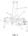
- the present invention can find application in the safety of loader cranes in general, such as loader cranes with slewing ring, according to the variant shown for example in Figure 2 .
- Crane 101 comprises a column 102 rotatable around its own axis, and one or more, possibly extendable, arms 103', 103".
- one or more additional extendable arms may optionally be provided. Extensibility of the arms, where provided, is achieved by a plurality of extensions 104 movable in translation relative to each other so that the axial extension of the respective arm can be changed. In the example in Figure 1 , only the second arm 103" is extendable by movement of the extensions 104.
- the first arm 103' lacking the extensions, will be referred to as the "main arm,” while the second arm 103", provided with the extensions 104, will be referred to as the "secondary arm.”
- the main arm 103' is rotatable with respect to column 102, while the secondary arm 103" is rotatable with respect to the main arm 103'.
- the free end 105 of the last extension of the secondary arm 103" is commonly referred to as the end-effector.
- a hook 106 that can be handled, for example, by a rope winch 107 may be provided at the end-effector 105.
- Crane 101 comprises a plurality of actuators to move the bodies forming the kinematic chain and support the related loads.
- a first hydraulic jack 108 which moves the main arm 103' relative to the column 102
- a second hydraulic jack 109 which moves the secondary arm 103' relative to the main arm 103'
- an actuator 111 for moving the column 102 relative to the fixed reference are visible.
- additional actuators 117 e.g., hydraulic, for moving the extensions 104, as well as an actuator, also e.g., hydraulic, for moving the winch 107.
- Column 102 can be rotatably coupled to a base 112 by means of a rotary coupling of various types.
- the rotary coupling between column 102 and base 112 can be of the rack-and- pinion type, or, according to the variant illustrated in Figure 2 , column 102 can, for example, be rotatably coupled to base 112 by means of a rotary coupling comprising a slewing ring 113.
- the term "slewing ring” refers to an axial bearing particularly suitable for low rotational speeds and high axial loads, comprising an inner ring and an outer ring coupled by means of one or more rows of balls or rollers such as to allow relative rotation.
- crane 101 in order to enable the supply to and withdrawal from the above-mentioned hydraulic actuators of a working fluid, specifically pressurized oil, crane 101 generally comprises a hydraulic circuit.
- the working fluid parameters determine the operating parameters of the crane itself. Specifically, the flow rate of working fluid affects the kinematic quantities of the articulated arm bodies and of the winch (in particular, the column rotation speed and the translation speed of the extensions, as well as the rotation speed of the winch), while the working fluid pressure affects the maximum load that can be lifted by them. Therefore, by changing the working parameters of the working fluid, the operating parameters (kinematics and maximum load) of crane 101 are changed accordingly.
- actuators are normally hydraulic, it is generally possible to provide actuators of a different nature (for example: electric or pneumatic). In these cases, too, it is of course possible to act on the actuators to change the operating parameters of the crane, particularly the kinematic magnitudes and the sustainable load. For example, in the case of electric rotary motors, limiting the maximum torque and angular speed of the motor will consequently limit the maximum sustainable load and the translation/rotation speeds of the arms. Similar considerations apply to pneumatic actuators, where limiting the pressure and flow rate of gas (e.g., air) will consequently limit the maximum sustainable load and translation/rotation speeds of the arms.
- gas e.g., air
- crane 101 may include suitable sensors for detecting the working parameters of the actuators that affect the crane's operating parameters.
- sensors may measure the flow rate and pressure of the working fluid.
- the crane 101 may comprise a plurality of sensors so that coordinates, such as Cartesian coordinates, of the end-effector 105 and/or its velocity can be determined.
- the plurality of sensors may include one or more of:
- sensors may include linear or angular encoders, magnetostrictive sensors, or similar. From the signals from the above sensors, it is possible, by means of geometric relations, to determine the absolute coordinates of end-effector 105, or even, by derivation in time, its velocity.
- a sensor such as a rotary sensor, can also be provided for determining the amount of cable unwrapped by the winch 107 and/or the rotational speed of the winch.
- Crane 101 comprises a control unit 115 functionally connected to the above-described actuators, for their movement, and to the possible sensors, to receive signals representative of the above-mentioned quantities and thus be able to move various moving bodies and/or the winch according to specific commands received.
- a user interface device 110 connected to the crane control unit 115 is also provided to allow an operator to move the crane and possibly access other functions.
- the user interface device 110 may comprise a radio control and the control unit 115 may comprise a transmission module to communicate with the latter (e.g., a radio transmission module).
- the operator can visually move the end-effector 105 and/or the hook 106 moved by the winch 107 by sending appropriate commands to the control unit 115 of the crane 101, in response to which the control unit 115 determines the operating parameters of the actuators necessary for the articulated arm and/or the winch to perform the movements desired by the operator, possibly carrying a load.
- the user interface device 110 may comprise a control panel located on the crane 101 itself, comprising, for example, levers and/or buttons operable by the operator.
- the control unit 115 then, under normal conditions, controls the actuators according to these operating parameters (hereinafter referred to as "regular operating parameters").
- regular operating parameters The above-mentioned sensors are conveniently exploited by the control unit of the crane 115 so that the movements commanded by the operator are carried out, in ways that are in themselves known to the skilled person.
- Crane 101 comprises at least one sensorized clamping member 114, connecting at least two of its parts, that is capable of sensing a stress acting on it.
- stress means a force or torque, static or dynamic, such as a clamping force or torque, or an external force acting on it, such as a shear force and/or a compressive or tensile axial force, or a torque or bending moment) and to provide a signal representative of the same.
- Such sensorized clamping members are known in the state of the art. They generally comprise a clamping body, such as a threaded rod, for mechanical clamping, alone or in cooperation with other complementary clamping bodies, such as a clamping nut.
- the clamping body includes a measurement module capable of measuring directly or indirectly, such as by ultrasound, stresses acting on the clamping body, as well as a transmission module, configured to transmit the measured physical quantity, wirelessly and/or via a data communication cable, to the crane control unit 115.
- the sensorized clamping member 114 can detect temperature, which can have an influence on the expansion of the clamping member itself and thus on the stress measurement.
- sensorized clamping member 114 is provided by WO 2022/084813 A1 , the contents of which are fully incorporated herein by reference.
- one of these sensorized clamping members 114 can connect the column 102 to the slewing ring 113, as shown in Figure 2 .
- only one of the clamping members between the column and the slewing ring is of the sensorized type, while the other clamping members are ordinary threaded connecting organs.
- one or more of the ordinary connecting organs, possibly all of them, can be replaced by as many sensorized clamping members 114.
- one or more additional sensorized clamping members 114 may be provided to connect the winch 107 to one of the arms 103', 103", as will be described in more detail below.
- the base 112 and the truck may be connected to each other via one or more sensorized clamping members 114.
- control unit 115 is further configured to control, in response to commands received from the operator via the radio control 110, at least some of the actuators according to operating parameters different from the regular operating parameters (hereinafter referred to as "modified operating parameters") depending on the stress-representative signal provided by the sensorized clamping members 114, in particular when one or more stresses indicative of a risk or failure condition are measured, for example low clamping force, overload or breakage.
- modified operating parameters different from the regular operating parameters
- Hazard or failure conditions that require actuators to be controlled according to modified operating parameters generally define possible situations in which the articulated crane must work with different, generally reduced, performance than under regular conditions.
- the speed of the end-effector 105 (and consequently of each of the articulated arm bodies) and/or the maximum load that can be lifted by the articulated arm is reduced.
- the maximum extension of the extensions may be limited, so as to limit the overall overhang of the end-effector 105 and thus the moment applied to the column 102.
- a first condition that may require the use of modified actuator operating parameters is the breakage or loosening of the tightening of one or more of the sensorized clamping members 114.
- control unit 115 can be configured to control the actuators according to modified operating parameters if the stress-representative signal, e.g., clamping force, provided by at least one of the sensorized clamping members 114 goes below a predetermined clamping force threshold value.
- stress-representative signal e.g., clamping force
- the clamping force measured in the sensorized clamping member is less than a threshold value less than or equal to the nominal clamping force established at the design stage, this may indicate a loosening of the screw and thus the need for the crane to be operated at reduced performance until the nominal clamping condition is restored.
- threshold values may be provided, to which different crane performances correspond.
- decreasing threshold values may be provided, corresponding to progressive loosening of the clamping member compared to the nominal clamping force, to which gradually decreasing performance of the crane corresponds, until it possibly stops. For example, in the case of zero force detection, this may mean that the clamping member has broken and therefore it may be necessary to stop the crane altogether.
- These threshold values can be stored, for example, in a memory module of control unit 115.
- An additional hazardous condition that may require the use of modified operating parameters of the actuators is overloading of the crane or any part of it, which results in overloading of the clamping members.
- Such a condition may occur, for example, in the case of excessive moment applied to the column, which results in overloading of the column's clamping members e.g., at the slewing ring, which may occur, for example, in the case of excessive overhang of the end-effector under a high load, or a load that is generically excessive in relation to the crane's capacity.
- control unit 115 can be configured to control the actuators according to modified operating parameters if the stress representative signal, for example, the force acting on at least one of the sensorized clamping members 114, exceeds a predetermined threshold force value above the nominal clamping force.
- Reduced performance may include a limitation of the overhang of the end-effector (thus a limitation of its Cartesian coordinates, which can be measured by the above-mentioned sensors, at least along the horizontal) and/or also a limitation of accelerations/decelerations that could result in additional overloads due to the forces/moments of inertia on the column.
- threshold values may be provided, to which different crane performance corresponds.
- increasing threshold values can be provided, corresponding to increasing load conditions, to which gradually decreasing crane performance or a gradually reduced overhang of the end-effector, up to possibly complete crane shutdown and/or total retraction of the extensions (i.e., minimum coordinates of the end-effector) correspond.
- additional threshold values can also be stored, for example, in the memory module of control unit 115.
- An additional hazardous condition that may require the use of modified operating parameters of the actuators is overloading of the winch 107, which results in overloading of the clamping members that connect the winch itself to the respective crane jib.
- the actuator that will be controlled according to modified operating parameters is the actuator that drives the winch.
- Such a condition may occur, for example, in case of excessive load applied to the winch hook, which results in overloading of members clamping the winch to the crane jib.
- control unit 115 can be configured to stop the actuator driving the winch 107 if the signal representative of the dynamic magnitude, e.g., the total sensed force, provided by at least one sensed clamping member 114 connecting the winch to the crane arm exceeds a predetermined threshold force value greater than the nominal clamping force of the sensed clamping member 114.
- one or more of the other actuators that move the articulated crane 101 bodies can also be controlled according to modified operating parameters in case of winch overload determined according to the above. This will prevent, for example, the load from being lifted not only by the winch, but also by moving the crane arms.
- a continuous change in the modified operating parameters can be provided by the control unit 115 with respect to the signals representative of the stress detected by the sensorized clamping members 114 according to specific predefined mathematical functions (e.g., linear functions).
- control unit 115 comprises a transmission module capable of transmitting the measured quantities by the one or more sensorized clamping members 114 to a remote control unit 116, such as a remote operations center, and receiving information from it.
- transmission can be via the Internet by taking advantage of a cellular data connection or a Wi-Fi network. This allows information on the status of the crane to be provided to such a remote operations center and, if necessary, interventions to be planned.
- the transmission module can be an integral part of the control unit 115 or, alternatively, it can be separate from the control unit 115 and operationally connected to it.
- the transmission of information between the remote operations center 116 and the control unit 115 of the crane 101 enables the following operations:
- the above-mentioned operations can be carried out directly on site, such as through the user interface device 110, which can be configured for this purpose to provide the above-mentioned information/alarms and perform the above-mentioned monitoring.
- each sensorized clamping member can communicate with the crane control unit 115 wirelessly or via cable.
- the wireless mode can be achieved by a direct Bluetooth ® connection between the crane control unit 115 and each of the sensorized clamping members 114, or via a gateway.
- the wired mode can, for example, take advantage of a CAN BUS line on the crane 101 itself.
- the crane control unit 115 and the sensorized clamping members 114 can be indirectly connected to each other via the remote control unit 116. This allows simultaneous transmission of sensed quantities to both the crane control unit 115 and the remote control unit 116 achieving the following advantages:
- control units as well as the elements referred to as “module,” may be implemented by hardware devices (e.g., control units), by software, or by a combination of hardware and software.
Landscapes
- Engineering & Computer Science (AREA)
- Mechanical Engineering (AREA)
- Control And Safety Of Cranes (AREA)
Applications Claiming Priority (1)
| Application Number | Priority Date | Filing Date | Title |
|---|---|---|---|
| IT102023000005319A IT202300005319A1 (it) | 2023-03-21 | 2023-03-21 | Sistema di sicurezza per la movimentazione di una gru articolata |
Publications (3)
| Publication Number | Publication Date |
|---|---|
| EP4434929A1 true EP4434929A1 (fr) | 2024-09-25 |
| EP4434929C0 EP4434929C0 (fr) | 2025-02-26 |
| EP4434929B1 EP4434929B1 (fr) | 2025-02-26 |
Family
ID=86657630
Family Applications (1)
| Application Number | Title | Priority Date | Filing Date |
|---|---|---|---|
| EP23210605.4A Active EP4434929B1 (fr) | 2023-03-21 | 2023-11-17 | Système de sécurité pour déplacer une grue articulée |
Country Status (3)
| Country | Link |
|---|---|
| EP (1) | EP4434929B1 (fr) |
| IT (1) | IT202300005319A1 (fr) |
| PL (1) | PL4434929T3 (fr) |
Citations (5)
| Publication number | Priority date | Publication date | Assignee | Title |
|---|---|---|---|---|
| JPH04338032A (ja) * | 1991-05-14 | 1992-11-25 | Kawasaki Steel Corp | リクレーマの設備診断方法 |
| DE102013005936A1 (de) * | 2013-04-05 | 2014-10-09 | Liebherr-Werk Biberach Gmbh | Kran |
| JP2014193766A (ja) * | 2013-03-29 | 2014-10-09 | Tadano Ltd | 旋回式ブーム作業機械のボルト緩み監視装置 |
| KR20180101065A (ko) * | 2017-03-03 | 2018-09-12 | 신상훈 | 전도 모우멘트를 활용한 고소작업대의 하중 감지장치 |
| WO2022084813A1 (fr) | 2020-10-22 | 2022-04-28 | Tokbo S.R.L. | Élément de serrage muni d'un capteur |
-
2023
- 2023-03-21 IT IT102023000005319A patent/IT202300005319A1/it unknown
- 2023-11-17 PL PL23210605.4T patent/PL4434929T3/pl unknown
- 2023-11-17 EP EP23210605.4A patent/EP4434929B1/fr active Active
Patent Citations (5)
| Publication number | Priority date | Publication date | Assignee | Title |
|---|---|---|---|---|
| JPH04338032A (ja) * | 1991-05-14 | 1992-11-25 | Kawasaki Steel Corp | リクレーマの設備診断方法 |
| JP2014193766A (ja) * | 2013-03-29 | 2014-10-09 | Tadano Ltd | 旋回式ブーム作業機械のボルト緩み監視装置 |
| DE102013005936A1 (de) * | 2013-04-05 | 2014-10-09 | Liebherr-Werk Biberach Gmbh | Kran |
| KR20180101065A (ko) * | 2017-03-03 | 2018-09-12 | 신상훈 | 전도 모우멘트를 활용한 고소작업대의 하중 감지장치 |
| WO2022084813A1 (fr) | 2020-10-22 | 2022-04-28 | Tokbo S.R.L. | Élément de serrage muni d'un capteur |
Also Published As
| Publication number | Publication date |
|---|---|
| EP4434929C0 (fr) | 2025-02-26 |
| PL4434929T3 (pl) | 2025-04-14 |
| EP4434929B1 (fr) | 2025-02-26 |
| IT202300005319A1 (it) | 2024-09-21 |
Similar Documents
| Publication | Publication Date | Title |
|---|---|---|
| EP0535339B1 (fr) | Système indicateur de couple de charge | |
| US11319193B2 (en) | Monitoring system and method | |
| EP1534583B1 (fr) | Systeme d'amarrage a commande active | |
| CN102259797A (zh) | 液压驱动的高精度水平调节吊具 | |
| JP2009511395A (ja) | 作業ブーム、特に大型マニピュレータおよび走行可能なコンクリートポンプ用作業ブーム | |
| US7497492B2 (en) | Hydraulic auxiliary hoist and crane control for high precision load positioning | |
| CN110685644B (zh) | 一种抽油机运行监测装置及故障预警系统 | |
| JP2005532968A (ja) | 積荷取扱装置用の制御システム | |
| KR20100069722A (ko) | 크레인 양중 운영 시스템 및 그를 이용하는 방법 | |
| KR100403765B1 (ko) | 하중물의 낙하 방지 기능을 갖는 천정 크레인 권상장치 | |
| KR101904359B1 (ko) | 다단붐 작업장치 상태모니터링 및 제어시스템 | |
| US10913643B1 (en) | Dual boom load monitoring | |
| EP4434929B1 (fr) | Système de sécurité pour déplacer une grue articulée | |
| CN111217298A (zh) | 基于智能传感器数字液压缸自动姿态调整装置及方法 | |
| CN113233334B (zh) | 一种直臂式随车起重机控制系统及其控制方法 | |
| EP2202194B1 (fr) | Élévateur de personnel | |
| JP2599504B2 (ja) | オートクレーン、大型ショベルカー等の装置の監視方法およびこの方法を実施するためのシステム | |
| EP3556710B1 (fr) | Grue avec bras articulé | |
| CN113979344B (zh) | 塔机四联动超大起重量的起升驱动系统及方法 | |
| CN116788992A (zh) | 一种用于起升机构钢丝绳补偿装置的控制方法 | |
| RU2237610C2 (ru) | Способ защиты грузоподъемного крана от перегрузки и повреждения и устройство для его осуществления | |
| RU2448037C1 (ru) | Ограничитель нагрузки грузоподъемной или строительной машины (варианты) | |
| US4141454A (en) | Crane with "Z" configured boom | |
| EP4345050A1 (fr) | Système adaptatif pour déplacer un bras articulé, en particulier d'une grue de chargement | |
| RU43257U1 (ru) | Система управления большегрузным краном |
Legal Events
| Date | Code | Title | Description |
|---|---|---|---|
| PUAI | Public reference made under article 153(3) epc to a published international application that has entered the european phase |
Free format text: ORIGINAL CODE: 0009012 |
|
| STAA | Information on the status of an ep patent application or granted ep patent |
Free format text: STATUS: THE APPLICATION HAS BEEN PUBLISHED |
|
| STAA | Information on the status of an ep patent application or granted ep patent |
Free format text: STATUS: REQUEST FOR EXAMINATION WAS MADE |
|
| AK | Designated contracting states |
Kind code of ref document: A1 Designated state(s): AL AT BE BG CH CY CZ DE DK EE ES FI FR GB GR HR HU IE IS IT LI LT LU LV MC ME MK MT NL NO PL PT RO RS SE SI SK SM TR |
|
| 17P | Request for examination filed |
Effective date: 20240902 |
|
| RBV | Designated contracting states (corrected) |
Designated state(s): AL AT BE BG CH CY CZ DE DK EE ES FI FR GB GR HR HU IE IS IT LI LT LU LV MC ME MK MT NL NO PL PT RO RS SE SI SK SM TR |
|
| RIC1 | Information provided on ipc code assigned before grant |
Ipc: B66C 23/90 20060101ALI20241104BHEP Ipc: B66C 23/00 20060101AFI20241104BHEP |
|
| GRAP | Despatch of communication of intention to grant a patent |
Free format text: ORIGINAL CODE: EPIDOSNIGR1 |
|
| STAA | Information on the status of an ep patent application or granted ep patent |
Free format text: STATUS: GRANT OF PATENT IS INTENDED |
|
| GRAS | Grant fee paid |
Free format text: ORIGINAL CODE: EPIDOSNIGR3 |
|
| INTG | Intention to grant announced |
Effective date: 20241223 |
|
| GRAA | (expected) grant |
Free format text: ORIGINAL CODE: 0009210 |
|
| STAA | Information on the status of an ep patent application or granted ep patent |
Free format text: STATUS: THE PATENT HAS BEEN GRANTED |
|
| AK | Designated contracting states |
Kind code of ref document: B1 Designated state(s): AL AT BE BG CH CY CZ DE DK EE ES FI FR GB GR HR HU IE IS IT LI LT LU LV MC ME MK MT NL NO PL PT RO RS SE SI SK SM TR |
|
| REG | Reference to a national code |
Ref country code: GB Ref legal event code: FG4D |
|
| REG | Reference to a national code |
Ref country code: CH Ref legal event code: EP |
|
| REG | Reference to a national code |
Ref country code: DE Ref legal event code: R096 Ref document number: 602023002213 Country of ref document: DE |
|
| REG | Reference to a national code |
Ref country code: IE Ref legal event code: FG4D |
|
| U01 | Request for unitary effect filed |
Effective date: 20250226 |
|
| U07 | Unitary effect registered |
Designated state(s): AT BE BG DE DK EE FI FR IT LT LU LV MT NL PT RO SE SI Effective date: 20250307 |
|
| REG | Reference to a national code |
Ref country code: SK Ref legal event code: T3 Ref document number: E 46069 Country of ref document: SK |
|
| PG25 | Lapsed in a contracting state [announced via postgrant information from national office to epo] |
Ref country code: RS Free format text: LAPSE BECAUSE OF FAILURE TO SUBMIT A TRANSLATION OF THE DESCRIPTION OR TO PAY THE FEE WITHIN THE PRESCRIBED TIME-LIMIT Effective date: 20250526 |
|
| PG25 | Lapsed in a contracting state [announced via postgrant information from national office to epo] |
Ref country code: ES Free format text: LAPSE BECAUSE OF FAILURE TO SUBMIT A TRANSLATION OF THE DESCRIPTION OR TO PAY THE FEE WITHIN THE PRESCRIBED TIME-LIMIT Effective date: 20250226 |
|
| PG25 | Lapsed in a contracting state [announced via postgrant information from national office to epo] |
Ref country code: IS Free format text: LAPSE BECAUSE OF FAILURE TO SUBMIT A TRANSLATION OF THE DESCRIPTION OR TO PAY THE FEE WITHIN THE PRESCRIBED TIME-LIMIT Effective date: 20250626 Ref country code: NO Free format text: LAPSE BECAUSE OF FAILURE TO SUBMIT A TRANSLATION OF THE DESCRIPTION OR TO PAY THE FEE WITHIN THE PRESCRIBED TIME-LIMIT Effective date: 20250526 |
|
| PG25 | Lapsed in a contracting state [announced via postgrant information from national office to epo] |
Ref country code: HR Free format text: LAPSE BECAUSE OF FAILURE TO SUBMIT A TRANSLATION OF THE DESCRIPTION OR TO PAY THE FEE WITHIN THE PRESCRIBED TIME-LIMIT Effective date: 20250226 |
|
| PG25 | Lapsed in a contracting state [announced via postgrant information from national office to epo] |
Ref country code: GR Free format text: LAPSE BECAUSE OF FAILURE TO SUBMIT A TRANSLATION OF THE DESCRIPTION OR TO PAY THE FEE WITHIN THE PRESCRIBED TIME-LIMIT Effective date: 20250527 |
|
| PG25 | Lapsed in a contracting state [announced via postgrant information from national office to epo] |
Ref country code: SM Free format text: LAPSE BECAUSE OF FAILURE TO SUBMIT A TRANSLATION OF THE DESCRIPTION OR TO PAY THE FEE WITHIN THE PRESCRIBED TIME-LIMIT Effective date: 20250226 |
|
| PG25 | Lapsed in a contracting state [announced via postgrant information from national office to epo] |
Ref country code: CZ Free format text: LAPSE BECAUSE OF FAILURE TO SUBMIT A TRANSLATION OF THE DESCRIPTION OR TO PAY THE FEE WITHIN THE PRESCRIBED TIME-LIMIT Effective date: 20250226 |
|
| U20 | Renewal fee for the european patent with unitary effect paid |
Year of fee payment: 3 Effective date: 20250915 |
|
| PLBE | No opposition filed within time limit |
Free format text: ORIGINAL CODE: 0009261 |
|
| STAA | Information on the status of an ep patent application or granted ep patent |
Free format text: STATUS: NO OPPOSITION FILED WITHIN TIME LIMIT |
|
| PGFP | Annual fee paid to national office [announced via postgrant information from national office to epo] |
Ref country code: PL Payment date: 20251024 Year of fee payment: 3 |
|
| PGFP | Annual fee paid to national office [announced via postgrant information from national office to epo] |
Ref country code: SK Payment date: 20251024 Year of fee payment: 3 |
|
| 26N | No opposition filed |
Effective date: 20251127 |