EP4435231A2 - Formation d'ouvertures de refroidissement dans un composant de moteur à turbine - Google Patents
Formation d'ouvertures de refroidissement dans un composant de moteur à turbine Download PDFInfo
- Publication number
- EP4435231A2 EP4435231A2 EP24161372.8A EP24161372A EP4435231A2 EP 4435231 A2 EP4435231 A2 EP 4435231A2 EP 24161372 A EP24161372 A EP 24161372A EP 4435231 A2 EP4435231 A2 EP 4435231A2
- Authority
- EP
- European Patent Office
- Prior art keywords
- aperture
- substrate
- coating
- cooling
- cooling aperture
- Prior art date
- Legal status (The legal status is an assumption and is not a legal conclusion. Google has not performed a legal analysis and makes no representation as to the accuracy of the status listed.)
- Granted
Links
Images



Classifications
-
- B—PERFORMING OPERATIONS; TRANSPORTING
- B23—MACHINE TOOLS; METAL-WORKING NOT OTHERWISE PROVIDED FOR
- B23K—SOLDERING OR UNSOLDERING; WELDING; CLADDING OR PLATING BY SOLDERING OR WELDING; CUTTING BY APPLYING HEAT LOCALLY, e.g. FLAME CUTTING; WORKING BY LASER BEAM
- B23K26/00—Working by laser beam, e.g. welding, cutting or boring
- B23K26/02—Positioning or observing the workpiece, e.g. with respect to the point of impact; Aligning, aiming or focusing the laser beam
- B23K26/06—Shaping the laser beam, e.g. by masks or multi-focusing
- B23K26/062—Shaping the laser beam, e.g. by masks or multi-focusing by direct control of the laser beam
- B23K26/0622—Shaping the laser beam, e.g. by masks or multi-focusing by direct control of the laser beam by shaping pulses
-
- F—MECHANICAL ENGINEERING; LIGHTING; HEATING; WEAPONS; BLASTING
- F01—MACHINES OR ENGINES IN GENERAL; ENGINE PLANTS IN GENERAL; STEAM ENGINES
- F01D—NON-POSITIVE DISPLACEMENT MACHINES OR ENGINES, e.g. STEAM TURBINES
- F01D5/00—Blades; Blade-carrying members; Heating, heat-insulating, cooling or antivibration means on the blades or the members
- F01D5/12—Blades
- F01D5/14—Form or construction
- F01D5/18—Hollow blades, i.e. blades with cooling or heating channels or cavities; Heating, heat-insulating or cooling means on blades
- F01D5/186—Film cooling
-
- B—PERFORMING OPERATIONS; TRANSPORTING
- B23—MACHINE TOOLS; METAL-WORKING NOT OTHERWISE PROVIDED FOR
- B23K—SOLDERING OR UNSOLDERING; WELDING; CLADDING OR PLATING BY SOLDERING OR WELDING; CUTTING BY APPLYING HEAT LOCALLY, e.g. FLAME CUTTING; WORKING BY LASER BEAM
- B23K26/00—Working by laser beam, e.g. welding, cutting or boring
- B23K26/36—Removing material
- B23K26/38—Removing material by boring or cutting
- B23K26/382—Removing material by boring or cutting by boring
-
- B—PERFORMING OPERATIONS; TRANSPORTING
- B23—MACHINE TOOLS; METAL-WORKING NOT OTHERWISE PROVIDED FOR
- B23K—SOLDERING OR UNSOLDERING; WELDING; CLADDING OR PLATING BY SOLDERING OR WELDING; CUTTING BY APPLYING HEAT LOCALLY, e.g. FLAME CUTTING; WORKING BY LASER BEAM
- B23K26/00—Working by laser beam, e.g. welding, cutting or boring
- B23K26/36—Removing material
- B23K26/40—Removing material taking account of the properties of the material involved
-
- F—MECHANICAL ENGINEERING; LIGHTING; HEATING; WEAPONS; BLASTING
- F01—MACHINES OR ENGINES IN GENERAL; ENGINE PLANTS IN GENERAL; STEAM ENGINES
- F01D—NON-POSITIVE DISPLACEMENT MACHINES OR ENGINES, e.g. STEAM TURBINES
- F01D5/00—Blades; Blade-carrying members; Heating, heat-insulating, cooling or antivibration means on the blades or the members
- F01D5/12—Blades
- F01D5/28—Selecting particular materials; Particular measures relating thereto; Measures against erosion or corrosion
- F01D5/284—Selection of ceramic materials
-
- F—MECHANICAL ENGINEERING; LIGHTING; HEATING; WEAPONS; BLASTING
- F01—MACHINES OR ENGINES IN GENERAL; ENGINE PLANTS IN GENERAL; STEAM ENGINES
- F01D—NON-POSITIVE DISPLACEMENT MACHINES OR ENGINES, e.g. STEAM TURBINES
- F01D5/00—Blades; Blade-carrying members; Heating, heat-insulating, cooling or antivibration means on the blades or the members
- F01D5/12—Blades
- F01D5/28—Selecting particular materials; Particular measures relating thereto; Measures against erosion or corrosion
- F01D5/288—Protective coatings for blades
-
- B—PERFORMING OPERATIONS; TRANSPORTING
- B23—MACHINE TOOLS; METAL-WORKING NOT OTHERWISE PROVIDED FOR
- B23K—SOLDERING OR UNSOLDERING; WELDING; CLADDING OR PLATING BY SOLDERING OR WELDING; CUTTING BY APPLYING HEAT LOCALLY, e.g. FLAME CUTTING; WORKING BY LASER BEAM
- B23K2101/00—Articles made by soldering, welding or cutting
- B23K2101/001—Turbines
-
- B—PERFORMING OPERATIONS; TRANSPORTING
- B23—MACHINE TOOLS; METAL-WORKING NOT OTHERWISE PROVIDED FOR
- B23K—SOLDERING OR UNSOLDERING; WELDING; CLADDING OR PLATING BY SOLDERING OR WELDING; CUTTING BY APPLYING HEAT LOCALLY, e.g. FLAME CUTTING; WORKING BY LASER BEAM
- B23K2103/00—Materials to be soldered, welded or cut
- B23K2103/50—Inorganic materials other than metals or composite materials
- B23K2103/52—Ceramics
-
- F—MECHANICAL ENGINEERING; LIGHTING; HEATING; WEAPONS; BLASTING
- F05—INDEXING SCHEMES RELATING TO ENGINES OR PUMPS IN VARIOUS SUBCLASSES OF CLASSES F01-F04
- F05D—INDEXING SCHEME FOR ASPECTS RELATING TO NON-POSITIVE-DISPLACEMENT MACHINES OR ENGINES, GAS-TURBINES OR JET-PROPULSION PLANTS
- F05D2220/00—Application
- F05D2220/30—Application in turbines
- F05D2220/32—Application in turbines in gas turbines
-
- F—MECHANICAL ENGINEERING; LIGHTING; HEATING; WEAPONS; BLASTING
- F05—INDEXING SCHEMES RELATING TO ENGINES OR PUMPS IN VARIOUS SUBCLASSES OF CLASSES F01-F04
- F05D—INDEXING SCHEME FOR ASPECTS RELATING TO NON-POSITIVE-DISPLACEMENT MACHINES OR ENGINES, GAS-TURBINES OR JET-PROPULSION PLANTS
- F05D2230/00—Manufacture
- F05D2230/10—Manufacture by removing material
-
- F—MECHANICAL ENGINEERING; LIGHTING; HEATING; WEAPONS; BLASTING
- F05—INDEXING SCHEMES RELATING TO ENGINES OR PUMPS IN VARIOUS SUBCLASSES OF CLASSES F01-F04
- F05D—INDEXING SCHEME FOR ASPECTS RELATING TO NON-POSITIVE-DISPLACEMENT MACHINES OR ENGINES, GAS-TURBINES OR JET-PROPULSION PLANTS
- F05D2230/00—Manufacture
- F05D2230/10—Manufacture by removing material
- F05D2230/12—Manufacture by removing material by spark erosion methods
-
- F—MECHANICAL ENGINEERING; LIGHTING; HEATING; WEAPONS; BLASTING
- F05—INDEXING SCHEMES RELATING TO ENGINES OR PUMPS IN VARIOUS SUBCLASSES OF CLASSES F01-F04
- F05D—INDEXING SCHEME FOR ASPECTS RELATING TO NON-POSITIVE-DISPLACEMENT MACHINES OR ENGINES, GAS-TURBINES OR JET-PROPULSION PLANTS
- F05D2230/00—Manufacture
- F05D2230/10—Manufacture by removing material
- F05D2230/13—Manufacture by removing material using lasers
-
- F—MECHANICAL ENGINEERING; LIGHTING; HEATING; WEAPONS; BLASTING
- F05—INDEXING SCHEMES RELATING TO ENGINES OR PUMPS IN VARIOUS SUBCLASSES OF CLASSES F01-F04
- F05D—INDEXING SCHEME FOR ASPECTS RELATING TO NON-POSITIVE-DISPLACEMENT MACHINES OR ENGINES, GAS-TURBINES OR JET-PROPULSION PLANTS
- F05D2230/00—Manufacture
- F05D2230/90—Coating; Surface treatment
Definitions
- This disclosure relates generally to a turbine engine and, more particularly, to formation of cooling apertures in a component of the turbine engine.
- a gas turbine engine includes various fluid cooled components such as turbine blades and turbine vanes.
- Such fluid cooled components may include one or more cooling apertures extending through a sidewall of the respective component.
- Various methods are known in the art for forming cooling apertures. While these known cooling aperture formation methods have various benefits, there is still room in the art form improvement.
- a manufacturing method is provided during which a substrate aperture is formed through a substrate of a preform component for a turbine engine using a first machining process.
- a coating system is applied onto the substrate to provide a coated substrate.
- a coating aperture is formed through the coating system using a second machining process that is different than the first machining process.
- the second machining process includes percussion laser drilling. At least the substrate aperture and the coating aperture collectively form a cooling aperture through the coated substrate.
- a substrate aperture is formed through a substrate of a preform component for a turbine engine.
- the substrate includes a substrate surface.
- a coating system is applied onto the substrate surface to provide a coated substrate.
- An orifice to the substrate aperture in the substrate surface is open at least as the coating system is initially applied onto the substrate surface.
- a coating aperture is formed through the coating system.
- At least the substrate aperture and the coating aperture collectively form a cooling aperture.
- a longitudinal length of the cooling aperture extends across the coated substrate from an inlet into the cooling aperture to an outlet from the cooling aperture.
- a cross-sectional geometry of the cooling aperture is uniform along the longitudinal length.
- a substrate aperture is formed through a substrate of a preform component for a turbine engine.
- the substrate includes a substrate surface.
- a coating system is applied onto the substrate surface to provide a coated substrate.
- the coating system extends over and covers an orifice to the substrate aperture in the substrate surface.
- a coating aperture is formed through the coating system.
- a cooling aperture extends longitudinally along a centerline through the coated substrate from an inlet to the cooling aperture to an outlet from the cooling aperture.
- the cooling aperture is formed by at least the substrate aperture and the coating aperture.
- the coating aperture has a coating aperture length that extends longitudinally along the centerline from the outlet, through the coating system, to the substrate aperture.
- a cross-sectional geometry of the coating aperture is constant along the coating aperture length.
- the coating aperture may be formed through the coating system using percussion laser drilling.
- the substrate aperture may be formed through the substrate using a first machining process.
- the coating aperture may be formed through the coating system using a second machining process that is different than the first machining process.
- the percussion laser drilling may have a pulse frequency between five and thirty hertz.
- the percussion laser drilling may use a single pulse or a series of short pulses with a high pulse frequency.
- Each of the series of short pulses may be less than 100 microseconds.
- the high pulse frequency may be greater than 100 hertz.
- the percussion laser drilling may use a single long pulse with a series of short pulses superimposed on top of the single long pulse.
- the single long pulse may be greater than 0.500 microseconds.
- Each of the series of short pulses may be less than 100 microseconds.
- the single long pulse may be greater than 1.000 microseconds.
- the first machining process may be electrical discharge machining.
- the first machining process may be abrasive water jet machining.
- the substrate aperture may be empty at least at a start of the applying of the coating system onto the substrate.
- the cooling aperture may extend longitudinally along a centerline through the coated substrate from an inlet into the cooling aperture to an outlet from the cooling aperture.
- the centerline may have a straight line geometry from the inlet to the outlet.
- the cooling aperture may extend longitudinally along a centerline through the coated substrate from an inlet into the cooling aperture to an outlet from the cooling aperture.
- the inlet and the outlet may have a common shape.
- the cooling aperture may extend longitudinally along a centerline through the coated substrate from an inlet into the cooling aperture to an outlet from the cooling aperture.
- the inlet and the outlet may have common dimensions.
- the cooling aperture may have a longitudinal length across the coated substrate measured from an inlet into the cooling aperture to an outlet from the cooling aperture.
- a cross-sectional geometry of the cooling aperture may be uniform along the longitudinal length.
- the cooling aperture may extend longitudinally along a centerline through the coated substrate from an inlet into the cooling aperture to an outlet from the cooling aperture.
- the outlet may be formed in an exterior surface of the coating system.
- the centerline may be angularly offset from the exterior surface by an angle between thirty and fifty degrees.
- the cooling aperture may extend longitudinally along a centerline through the coated substrate from an inlet into the cooling aperture to an outlet from the cooling aperture.
- the outlet may be formed in an exterior surface of the coating system.
- the centerline may be angularly offset from the exterior surface by an angle between twenty and forty degrees.
- the cooling aperture may extend longitudinally along a centerline through the coated substrate from an inlet into the cooling aperture to an outlet from the cooling aperture.
- the outlet may be formed in an exterior surface of the coating system.
- the centerline may be angularly offset from the exterior surface by an angle between forty and sixty degrees.
- the substrate may be or otherwise include metal.
- the coating system may be or otherwise include a ceramic coating over the metal.
- the coating system may also include a bond coating between the metal and the ceramic coating.
- the preform component may be or otherwise include a preform of a flowpath wall for the turbine engine.
- the preform component may be or otherwise include a preform of a combustor liner for the turbine engine.
- the present disclosure may include any one or more of the individual features disclosed above and/or below alone or in any combination thereof.
- the present disclosure includes methods for manufacturing fluid cooled components of a gas turbine engine.
- the turbine engine may be described below as a turbofan turbine engine.
- the present disclosure is not limited to such an exemplary gas turbine engine.
- the turbine engine may alternatively be configured as a turbojet turbine engine, a turboprop turbine engine, a turboshaft turbine engine, a propfan turbine engine, a pusher fan turbine engine or an auxiliary power unit (APU) turbine engine.
- the turbine engine may be configured as a geared turbine engine or a direct drive turbine engine.
- the present disclosure is also not limited to aircraft applications.
- the turbine engine for example, may alternatively be configured as a ground-based industrial turbine engine for power generation, or any other type of turbine engine which utilizes fluid cooled components.
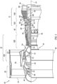
- FIG. 1 is a side cutaway illustration of the turbofan turbine engine 20.
- This turbine engine 20 extends along an axial centerline 22 between a forward, upstream airflow inlet 24 and an aft, downstream airflow exhaust 26.
- the turbine engine 20 includes a fan section 28, a compressor section 29, a combustor section 30, a turbine section 31 and an exhaust section 32 (partially shown in FIG. 1 ).
- the compressor section 29 includes a low pressure compressor (LPC) section 29A and a high pressure compressor (HPC) section 29B.
- the turbine section 31 includes a high pressure turbine (HPT) section 31A and a low pressure turbine (LPT) section 31B.
- the engine sections 28-31 are arranged sequentially along the axial centerline 22 within an engine housing 34.
- This engine housing 34 includes an inner case 36 (e.g., a core case) and an outer case 38 (e.g., a fan case).
- the inner case 36 may house one or more of the engine sections 29A-31B; e.g., a core of the turbine engine 20.
- the outer case 38 may house at least the fan section 28.
- Each of the engine sections 28, 29A, 29B, 31A and 31B includes a respective bladed rotor 40-44.
- Each of these bladed rotors 40-44 includes a plurality of rotor blades arranged circumferentially around and connected to one or more respective rotor disks.
- the rotor blades may be formed integral with or mechanically fastened, welded, brazed, adhered and/or otherwise attached to the respective rotor disk(s).
- the fan rotor 40 is connected to a geartrain 46, for example, through a fan shaft 48.
- the geartrain 46 and the LPC rotor 41 are connected to and driven by the LPT rotor 44 through a low speed shaft 49.
- the HPC rotor 42 is connected to and driven by the HPT rotor 43 through a high speed shaft 50.
- the shafts 48-50 are rotatably supported by a plurality of bearings 52; e.g., rolling element and/or thrust bearings. Each of these bearings 52 is connected to the engine housing 34 by at least one stationary structure such as, for example, an annular support strut.
- This air is directed through the fan section 28 and into a core flowpath 54 and a bypass flowpath 56.
- the core flowpath 54 extends sequentially through the engine sections 29A-32; e.g., the engine core.
- the air within the core flowpath 54 may be referred to as "core air”.
- the bypass flowpath 56 extends through a bypass duct, which bypasses the engine core.
- the air within the bypass flowpath 56 may be referred to as "bypass air”.
- the core air is compressed by the LPC rotor 41 and the HPC rotor 42 and directed into a combustion chamber 58 of a combustor in the combustor section 30.
- Fuel is injected into the combustion chamber 58 and mixed with the compressed core air to provide a fuel-air mixture.
- This fuel air mixture is ignited and combustion products thereof flow through and sequentially cause the HPT rotor 43 and the LPT rotor 44 to rotate.
- the rotation of the HPT rotor 43 and the LPT rotor 44 respectively drive rotation of the HPC rotor 42 and the LPC rotor 41 and, thus, compression of the air received from a core airflow inlet.
- the rotation of the LPT rotor 44 also drives rotation of the fan rotor 40, which propels the bypass air through and out of the bypass flowpath 56.
- the propulsion of the bypass air may account for a majority of thrust generated by the turbine engine 20; e.g., more than seventy-five percent (75%) of engine thrust.
- the turbine engine 20 of the present disclosure is not limited to the foregoing exemplary thrust ratio.
- the turbine engine 20 includes a plurality of fluid cooled components (e.g., 60A-H; generally referred to as "60") arranged within, for example, the combustor section 30, the turbine section 31 and/or the exhaust section 32.
- these fluid cooled components 60 include airfoils such as, but not limited to, a rotor blade airfoil (e.g., 60A, 60D) and a stator vane airfoil (e.g., 60B, 60C, 60H).
- fluid cooled components 60 include flowpath walls such as, but not limited to, a combustor liner (e.g., 60F), an exhaust duct liner (e.g., 60E), a shroud or other flowpath wall (e.g., 60G), a rotor blade platform and a stator vane platform.
- flowpath walls such as, but not limited to, a combustor liner (e.g., 60F), an exhaust duct liner (e.g., 60E), a shroud or other flowpath wall (e.g., 60G), a rotor blade platform and a stator vane platform.
- flowpath walls such as, but not limited to, a combustor liner (e.g., 60F), an exhaust duct liner (e.g., 60E), a shroud or other flowpath wall (e.g., 60G), a rotor blade platform and a stator vane platform.
- combustor liner e
- FIG. 2 illustrates a portion of one of the fluid cooled components 60 within the turbine engine 20.
- This fluid cooled component 60 has a component wall 62 (e.g., a sidewall or an endwall) configured with one or more cooling apertures 64 such as effusion apertures.
- the component wall 62 has a thickness 66 that extends vertically (e.g., along a z-axis) between and to a first surface 68 of the component wall 62 and a second surface 70 of the component wall 62.
- the component first surface 68 may be configured as an interior and/or a cold side surface of the component wall 62.
- the component first surface 68 may at least partially form a peripheral boundary of a cooling fluid volume 72 (e.g., a cavity or a passage) along the component wall 62.
- the component first surface 68 may thereby be subject to relatively cool fluid (e.g., cooling air) supplied to the cooling fluid volume 72.
- This cooling fluid volume 72 may be an internal volume formed within the fluid cooled component 60 where, for example, the component 60 is an airfoil. Alternatively, the cooling fluid volume 72 may be an external volume formed external to the fluid cooled component 60 where, for example, the component 60 is a flowpath wall.
- the component second surface 70 may be configured as an exterior and/or a hot side surface of the component wall 62. The component second surface 70, for example, may at least partially form a peripheral boundary of a portion of, for example, the core flowpath 54 along the component wall 62. The component second surface 70 may thereby be subject to relative hot fluid (e.g., combustion products) flowing through the core flowpath 54 within, for example, one of the engine sections 30-32 of FIG. 1 .
- the component wall 62 of FIG. 3 includes a component substrate 74 and a coating system 76.
- the coating system 76 may include one or more external component coatings 78 and 80 over the component substrate 74.
- the component substrate 74 at least partially or completely forms and carries the component first surface 68.
- the component substrate 74 has a thickness 82 that extends vertically (e.g., along the z-axis) between and to the component first surface 68 and a second surface 84 of the component substrate 74.
- the substrate second surface 84 may be configured as an exterior surface of the component substrate 74 prior to being (e.g., partially or completely) covered by the coating system 76 and its one or more component coatings 78 and 80.
- the substrate thickness 82 may be greater than one-half (1/2) of the wall thickness 66.
- the substrate thickness 82 for example, may be between two-third (2/3) and four-fifths (4/5) of the wall thickness 66. In other embodiments, however, it is contemplated the substrate thickness 82 may be greater than four-fifths (4/5) of the wall thickness 66 or less than one-half (1/2) of the wall thickness 66.
- the component substrate 74 is constructed from substrate material 86.
- This substrate material 86 may be an electrically conductive material.
- the substrate material 86 may be or otherwise include metal.
- the metal include, but are not limited to, nickel (Ni), titanium (Ti), aluminum (Al), chromium (Cr), cobalt (Co), and alloys thereof.
- the metal for example, may be a nickel or cobalt based superalloy such as, but not limited to, PWA 1484 or PWA 1429.
- the inner coating 78 may be configured as a bond coating between the component substrate 74 and the outer coating 80.
- the inner coating 78 of FIG. 3 is bonded (e.g., directly) to the substrate second surface 84.
- the inner coating 78 at least partially or completely covers the substrate second surface 84 (e.g., along an x-y plane of FIG. 2 ).
- the inner coating 78 has a thickness 88 that extends vertically (e.g., along the z-axis) between and to the component substrate 74 and the outer coating 80.
- This inner coating thickness 88 may be less than oneseventh (1/7) of the wall thickness 66.
- the inner coating thickness 88 for example, may be between one-eighth (1/8) and one-fortieth (1/40) of the wall thickness 66.
- the inner coating 78 is constructed from inner coating material 90.
- This inner coating material 90 may be an electrically conductive material.
- the inner coating material 90 may be or otherwise include metal.
- the metal include, but are not limited to, MCrAlY and MAlCrX, where "M” is nickel (Ni), cobalt (Co), iron (Fe) or any combination thereof, and where "Y” or “X” is hafnium (Hf), yttrium (Y), silicon (Si) or any combination thereof.
- the MCrAlY and MAlCrX may be further modified with strengthening elements such as, but not limited to, tantalum (Ta), rhenium (Re), tungsten (W), molybdenum (Mo) or any combination thereof.
- An example of the MCrAlY is PWA 286.
- the inner coating 78 may be formed from a single layer of the inner coating material 90.
- the inner coating 78 may alternatively be formed from a plurality of layers of the inner coating material 90, where the inner coating material 90 within each of those inner coating layers may be the same as one another or different from one another.
- the outer coating 80 has a thickness 94 that extends vertically (e.g., along the z-axis) between and to the inner coating 78 and the component second surface 70.
- This outer coating thickness 94 may be less than one-half (1/2) of the wall thickness 66.
- the outer coating thickness 94 for example, may be between one-third (1/3) and one-eighth (1/8) of the wall thickness 66. In other embodiments, however, it is contemplated the outer coating thickness 94 may be greater than one-half (1/2) of the wall thickness 66 or less than one-eighth (1/8) of the wall thickness 66.
- the outer coating 80 is constructed from outer coating material 96.
- This outer coating material 96 may be a non-electrically conductive material.
- the outer coating material 96 may be or otherwise include ceramic. Examples of the ceramic include, but are not limited to, yttria stabilized zirconia (YSZ) and gadolinium zirconate (GdZ).
- the outer coating material 96 of the present disclosure is not limited to non-electrically conductive materials. In other embodiments, for example, the outer coating material 96 may be an electrically conductive material; e.g., metal.
- the outer coating 80 may be formed from a single layer of the outer coating material 96.
- the outer coating 80 may alternatively be formed from a plurality of layers of the outer coating material 96, where the outer coating material 96 within each of those outer coating layers may be the same as one another or different from one another.
- the outer coating 80 may include a thin interior layer of the YSZ and a thicker exterior later of the GdZ.
- Each of the cooling apertures 64 extends along a longitudinal centerline 98 of the respective cooling aperture 64 between and to an inlet 100 into the respective cooling aperture 64 and an outlet 102 from the respective cooling aperture 64.
- This aperture centerline 98 may have a straight line geometry (e.g., in the x-y plane, in an x-z plane and/or in a y-z plane) from the cooling aperture inlet 100, through the component wall 62, to the cooling aperture outlet 102.
- the aperture centerline 98 of FIG. 3 is angularly offset from the component first surface 68 by a first angle 104
- the aperture centerline 98 is angularly offset from the component second surface 70 by a second angle 106.
- the first angle 104 and the second angle 106 are each acute angles.
- the first angle 104 and the second angle 106 may each be between ten degrees (10°) and eighty degrees (80°); e.g., between twenty degrees (20°) and forty degrees (40°), between thirty degrees (30°) and fifty degrees (50°), or between forty degrees (40°) and sixty degrees (60°).
- the first angle 104 and the second angle 106 may each be greater than eighty degrees (80°); e.g., a ninety degree (90°) right angle.
- the cooling aperture inlet 100 of FIG. 3 is located in the component first surface 68.
- the cooling aperture inlet 100 thereby fluidly couples its respective cooling aperture 64 with the cooling fluid volume 72 along the component first surface 68.
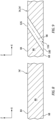
- the cooling aperture inlet 100 has a cross-sectional geometry when viewed in a reference plane parallel with the component first surface 68 at the respective cooling aperture inlet 100.
- This inlet geometry of FIG. 4 has a round shape (e.g., an oval shape) with a first dimension 108 (e.g., a minor axis dimension) and a second dimension 110 (e.g., a major axis dimension), where the second dimension 110 of FIG. 4 is greater than the first dimension 108.
- the cooling aperture outlet 102 of FIG. 3 is located in the component second surface 70.
- the cooling aperture outlet 102 thereby fluidly couples its respective cooling aperture 64 with the core flowpath 54 along the component second surface 70.
- the cooling aperture outlet 102 has a cross-sectional geometry when viewed in a reference plane parallel with the component second surface 70 at the respective cooling aperture outlet 102.
- This outlet geometry of FIG. 5 has a round shape (e.g., an oval shape) with a first dimension 112 (e.g., a minor axis dimension) and a second dimension 114 (e.g., a major axis dimension), where the second dimension 114 of FIG. 4 is greater than the first dimension 112.
- the outlet geometry may be exactly or substantially the same as the inlet geometry of FIG. 4 .
- the cooling aperture outlet round shape of FIG. 5 may be exactly or substantially the same as the cooling aperture inlet round shape of FIG. 4 .
- the cooling aperture outlet first dimension 112 of FIG. 5 may be exactly or substantially equal to the cooling aperture inlet first dimension 108 of FIG. 4 .
- the cooling aperture outlet second dimension 114 of FIG. 5 may be exactly or substantially equal to the cooling aperture inlet second dimension 110 of FIG. 4 .
- each cooling aperture 64 may be formed by at least (or only) a substrate aperture 116 and a coating aperture 118.
- the substrate aperture 116 extends longitudinally along the aperture centerline 98 through the component substrate 74 from the cooling aperture inlet 100 to the coating aperture 118.
- the coating aperture 118 extends longitudinally along the aperture centerline 98 through the coating system 76 and its members 78 and 80 from the cooling aperture outlet 102 to the substrate aperture 116.
- a cross-sectional geometry (e.g., shape and dimensions) of the substrate aperture 116 along a longitudinal length 120 of that substrate aperture 116 may be uniform (e.g., constant, the same) from the cooling aperture inlet 100 to the coating aperture 118.
- a cross-sectional geometry (e.g., shape and dimensions) of the coating aperture 118 along a longitudinal length 122 of that coating aperture 118 may be uniform (e.g., constant, the same) from the cooling aperture outlet 102 to the substrate aperture 116.
- a cross-sectional geometry (e.g., shape and dimensions) of the cooling aperture 64 may be uniform (e.g., the same, constant) along a longitudinal length 124 of that cooling aperture 64 from the cooling aperture inlet 100 to the cooling aperture outlet 102.
- each cooling aperture 64 may be configured without a diffuser section at its cooling aperture outlet 102.
- the term "diffuser section" may describe a section of a cooling hole with dimensions that increase as that cooling hole section extends towards / to an outlet of the cooling hole.
- each aperture 64, 116, 118 when viewed in a plane perpendicular to the aperture centerline 98, each aperture 64, 116, 118 may have a circular shape. Of course, in other embodiments, it is contemplated the aperture 64, 116, 118 may alternatively have a non-circular shape; e.g., an oval shape, etc.
- the term “manufacturing” may describe a method for forming the fluid cooled component 60; e.g., creating a brand new fluid cooled component.
- the term “manufacturing” may also or alternatively describe a method for repairing the fluid cooled component 60; e.g., restoring one or more features of a previously formed fluid cooled component to brand new condition, similar to brand new condition or better than brand new condition.
- the fluid cooled component 60 may be repaired to fix one or more defects (e.g., cracks, wear and/or other damage) imparted during previous use of the fluid cooled component 60.
- the fluid cooled component 60 may also or alternatively be repaired to fix one or more defects imparted during the initial formation of the fluid cooled component 60.
- the manufacturing method 700 is described below with respect to the initial forming of a brand new fluid cooled component 60.
- the substrate aperture 116 of a respective cooling aperture 64 is formed in the preform substrate 74'.
- a portion of the substrate material 86 is machined away (e.g., from an exterior or an interior of the preform substrate 74') to form the substrate aperture 116.
- This substrate aperture 116 extends along the aperture centerline 98 (e.g., completely) through the substrate material 86 between and to the component first surface 68 and the substrate second surface 84.
- the substrate aperture 116 may be formed in the (e.g., electrically conductive, metal) substrate material 86 using a substrate machining process.
- This substrate machining process may be or otherwise include an electrical discharge machining (EDM) process or an abrasive water jet (AWJ) machining process.
- EDM electrical discharge machining
- AAWJ abrasive water jet
- an electrode for the EDM process may be, but is not limited to, a "comb" type electrical discharge machining electrode or a high speed electrical discharge machining (HSEDM) electrode.
- Such substrate machining processes may quickly, precisely and efficiently form the substrate aperture 116 in the substrate material 86.
- such substrate machining processes may facilitate lower remelt thicknesses and/or a reduced propensity for cracking than when using, for example, a laser drilling process.
- the manufacturing method 700 of the present disclosure is not limited to such an exemplary substrate machining process.
- the substrate aperture 116 may alternatively (or also) be formed using one or more other machining processes such as, but not limited to, a laser machining process (e.g., percussion laser drilling, laser ablation, etc.), an electron beam machining process and a mechanical drilling process.
- a laser machining process e.g., percussion laser drilling, laser ablation, etc.
- an electron beam machining process e.g., a mechanical drilling process.
- a preform inner coating 78' is applied over the component substrate 74; e.g., the now apertured preform substrate 74'.
- the inner coating material 90 may be applied (e.g., deposited) onto the substrate second surface 84 of the component substrate 74.
- This preform inner coating 78' may generally have the same configuration of the inner coating 78 for the fluid cooled component 60 to be formed (e.g., see FIG. 3 ).
- the preform inner coating 78' of FIG. 10 does not include any holes therein for forming the cooling apertures 64 or their coating apertures 118.
- the inner coating material 90 may be applied using various inner coating application techniques.
- the inner coating application techniques include, but are not limited to, a physical vapor deposition (PVD) process, chemical vapor deposition (CVD) process, a plating process and a thermal spray process.
- the thermal spray process include, but are not limited to, a plasma spray (PS) process, a high velocity oxygen fuel (HVOF) process, a high velocity air fuel (HVAF) process, a wire spray process or a combustion spray process.
- PS plasma spray
- HVOF high velocity oxygen fuel
- HVAC high velocity air fuel
- the inner coating application may be performed via a non-line-of-sight (NLOS) coating process or a direct-line-of-sight (DLOS) coating process.
- NLOS non-line-of-sight
- DLOS direct-line-of-sight
- the inner coating material 90 may extend over and (e.g., completely) cover or otherwise cap / plug an orifice 126 of the substrate aperture 116 in the substrate second surface 84 being coated.
- the preform inner coating 78' may be applied while the substrate aperture 116 and its orifice 126 in the substrate second surface 84 are open.
- the substrate aperture 116 may alternatively be plugged with masking material to reduce or prevent the inner coating material 90 from entering the substrate aperture 116.
- a preform outer coating 80' is applied over the component substrate 74 and the preform inner coating 78'.
- the outer coating material 96 may be applied (e.g., deposited) onto the inner coating second surface 92 of the preform inner coating 78'.
- This preform outer coating 80' may generally have the same configuration of the outer coating 80 for the fluid cooled component 60 to be formed (e.g., see FIG. 3 ).
- the preform outer coating 80' of FIG. 11 does not include any holes therein for forming the cooling apertures 64 or their coating apertures 118.
- a combination of the preform inner coating 78' and the preform outer coating 80' form a preform 76' of the coating system 76 over the component substrate 74.
- the outer coating material 96 may be applied using various outer coating application techniques.
- the outer coating application techniques include, but are not limited to, a physical vapor deposition (PVD) process, chemical vapor deposition (CVD) process, a plating process and a thermal spray process.
- the thermal spray process include, but are not limited to, a plasma spray (PS) process, a high velocity oxygen fuel (HVOF) process, a high velocity air fuel (HVAF) process, a wire spray process or a combustion spray process.
- PS plasma spray
- HVOF high velocity oxygen fuel
- HVAC high velocity air fuel
- the inner coating application may be performed via a non-line-of-sight (NLOS) coating process or a direct-line-of-sight (DLOS) coating process.
- NLOS non-line-of-sight
- DLOS direct-line-of-sight
- the outer coating material 96 may further extend over and (e.g., completely) cover or otherwise cap / plug the orifice 126 of the substrate aperture 116.
- the outer coating material 96 may further extend over and (e.g., completely) cover or otherwise cap / plug the orifice 126 of the substrate aperture 116.
- at least a portion or the entirety of the substrate aperture 116 may be (or remain) empty.
- at least a portion (or an entirety) of the substrate aperture 116 may alternatively be plugged with masking material to reduce or prevent the inner coating material 90 from entering the substrate aperture 116.
- the combination of the component substrate 74, the preform inner coating 78' and the preform outer coating 80' may provide a preform component 60'.
- This preform component 60' of FIG. 11 may generally have the configuration of the fluid cooled component 60 to be formed (e.g., see FIG. 3 ).
- the preform component 60' of FIG. 11 does not include any holes for forming the cooling apertures 64 and their coating apertures 118 through the preform coating system 76' and its preform inner and outer coatings.
- step 710 referring to FIG. 3 , the coating aperture 118 of the respective cooling aperture 64 is formed in the preform component 60' (see FIG. 11 ).
- a portion of the preform coating system 76' and its outer coating material 96 and its inner coating material 90 is machined away (e.g., from the exterior of the preform component 60') to form the coating aperture 118.
- This formation step 710 may also remove any coating material (e.g., 90 and/or 96) which may be disposed in the substrate aperture 116.
- the coating aperture 118 is aligned with the substrate aperture 116.
- the coating aperture 118 may be formed in the coating system 76 using a coating machining process.
- This coating machining process may be or otherwise include a laser drilling process.
- the coating machining process may be a (e.g., fixed position) percussion laser drilling process.
- This percussion laser drilling process may be performed with a fixed position laser beam where the laser beam may be stationary through the forming of the coating aperture 118.
- the laser drilling may be performed without trepanning, changing an angle of attack of the laser beam, etc.
- the percussion laser drilling process may have a pulse frequency between five and thirty hertz (Hz). More particularly, the percussion laser drilling may be performed at a low enough energy to reduce heat generation.
- the percussion laser drilling process may have a single pulse or a series of short pulses (e.g., less than 100 microseconds) with a high pulse frequency (e.g., greater than 100 Hertz).
- the percussion laser drilling process may have a single long pulse (e.g., greater than 0.500 or 1.000 milliseconds) with a series of short number of pulses superimposed on top of the long pulse.
- the manufacturing method 700 of the present disclosure is not limited to such an exemplary coating machining process.
- the coating aperture 118 may alternatively (or also) be formed using one or more other machining processes such as, but not limited to, a laser ablation process, an electron beam machining process and a mechanical drilling process.
- the substrate aperture 116 may be formed using precise and low cost machining processes such as the electrical discharge machining (EDM) process.
- EDM electrical discharge machining
- heat generated during the formation of the substrate aperture 116 may be well dissipated prior to formation of a bond between the coating system 76 and the component substrate 74. It has been observed that delamination may occur between an inner coating and a substrate and/or between an inner coating and an outer coating when materials of those members are subject to relatively high heat loads. Since the coating system 76 is not applied to the component substrate 74 during the forming the substrate aperture 116, the manufacturing method 700 may prevent delamination due to formation of the cooling aperture 64 through the component substrate 74.
- the energy input to form the coating aperture 118 may also be reduced thereby further reducing potential for delamination. Reducing heat input and the potential for delamination may in turn facilitate increasing a density of the cooling apertures 64 in the component wall 62. This may be particularly useful where the component wall 62 is configured as a flowpath wall such as a combustor liner.
- the substrate aperture 116 and the coating aperture 118 are aligned to form the cooling aperture 64.
- Various techniques may be used to facilitate this alignment. For example, the location and orientation of the substrate aperture(s) 116 may be mapped prior to the application of the coating system 76. A control system may then map out locations for forming the substrate apertures 116.
- various non-contact, non-destructive imaging processes may be used to locate the substrate aperture(s) 116 below the coating system 76. Examples of these imaging processes include, but are not limited to, a micro computed tomography (micro-CT) imaging process, a terahertz imaging process, a flash thermography process and a microwave imaging process.
- micro-CT micro computed tomography
- the coating system 76 may include multiple members.
- the coating system 76 of FIG. 3 includes the inner coating 78 and the outer coating 80.
- the coating system 76 may include one or more additional coatings such as, but not limited to, a corrosion resistant coating (e.g., PWA 275) and/or another ceramic coating.
- the coating system 76 may be formed from a single material and/or a single coating; e.g., the outer coating 80.
Landscapes
- Engineering & Computer Science (AREA)
- Physics & Mathematics (AREA)
- Optics & Photonics (AREA)
- Mechanical Engineering (AREA)
- Plasma & Fusion (AREA)
- Chemical & Material Sciences (AREA)
- General Engineering & Computer Science (AREA)
- Materials Engineering (AREA)
- Ceramic Engineering (AREA)
- Turbine Rotor Nozzle Sealing (AREA)
- Laser Beam Processing (AREA)
Applications Claiming Priority (1)
| Application Number | Priority Date | Filing Date | Title |
|---|---|---|---|
| US18/117,450 US20240293892A1 (en) | 2023-03-05 | 2023-03-05 | Forming cooling aperture(s) in a turbine engine component |
Publications (3)
| Publication Number | Publication Date |
|---|---|
| EP4435231A2 true EP4435231A2 (fr) | 2024-09-25 |
| EP4435231A3 EP4435231A3 (fr) | 2024-10-30 |
| EP4435231B1 EP4435231B1 (fr) | 2026-08-19 |
Family
ID=90362064
Family Applications (1)
| Application Number | Title | Priority Date | Filing Date |
|---|---|---|---|
| EP24161372.8A Active EP4435231B1 (fr) | 2023-03-05 | 2024-03-05 | Formation d'ouvertures de refroidissement dans un composant de moteur à turbine |
Country Status (2)
| Country | Link |
|---|---|
| US (1) | US20240293892A1 (fr) |
| EP (1) | EP4435231B1 (fr) |
Cited By (1)
| Publication number | Priority date | Publication date | Assignee | Title |
|---|---|---|---|---|
| EP4745366A1 (fr) * | 2024-11-14 | 2026-05-20 | RTX Corporation | Procédé de fabrication pour formation d'ouverture(s) dans un composant à l'aide de données de balayage par tomographie assistée par ordinateur mises à l'échelle |
Families Citing this family (1)
| Publication number | Priority date | Publication date | Assignee | Title |
|---|---|---|---|---|
| US12618561B1 (en) | 2025-02-17 | 2026-05-05 | Rtx Corporation | Combustion liner having cooling holes with stepped lateral sidewalls |
Family Cites Families (32)
| Publication number | Priority date | Publication date | Assignee | Title |
|---|---|---|---|---|
| US4808785A (en) * | 1986-11-13 | 1989-02-28 | Chromalloy Gas Turbine Corporation | Method and apparatus for making diffused cooling holes in an airfoil |
| US4762464A (en) * | 1986-11-13 | 1988-08-09 | Chromalloy Gas Turbine Corporation | Airfoil with diffused cooling holes and method and apparatus for making the same |
| US5216808A (en) * | 1990-11-13 | 1993-06-08 | General Electric Company | Method for making or repairing a gas turbine engine component |
| US5683600A (en) * | 1993-03-17 | 1997-11-04 | General Electric Company | Gas turbine engine component with compound cooling holes and method for making the same |
| US5465780A (en) * | 1993-11-23 | 1995-11-14 | Alliedsignal Inc. | Laser machining of ceramic cores |
| US6368060B1 (en) * | 2000-05-23 | 2002-04-09 | General Electric Company | Shaped cooling hole for an airfoil |
| US6441341B1 (en) * | 2000-06-16 | 2002-08-27 | General Electric Company | Method of forming cooling holes in a ceramic matrix composite turbine components |
| US6663919B2 (en) * | 2002-03-01 | 2003-12-16 | General Electric Company | Process of removing a coating deposit from a through-hole in a component and component processed thereby |
| GB2406300A (en) * | 2003-09-20 | 2005-03-30 | Rolls Royce Plc | A method of laser machining components having a protective surface coating |
| WO2005044508A1 (fr) * | 2003-10-06 | 2005-05-19 | Siemens Aktiengesellschaft | Procede pour produire un trou et dispositif |
| EP1767743A1 (fr) * | 2005-09-26 | 2007-03-28 | Siemens Aktiengesellschaft | Méthode de fabrication d'un composant de turbine à gaz revêtu et ayant des ouvertures, dispositif pour l'application de ladite méthode et aube de turbine ayant des trous de refroidissement |
| EP1844892A1 (fr) * | 2006-04-13 | 2007-10-17 | ALSTOM Technology Ltd | Méthode d'enlèvement de revêtement des trous de refroidissement d'une pièce de turbine |
| US7820267B2 (en) * | 2007-08-20 | 2010-10-26 | Honeywell International Inc. | Percussion drilled shaped through hole and method of forming |
| US9696035B2 (en) * | 2010-10-29 | 2017-07-04 | General Electric Company | Method of forming a cooling hole by laser drilling |
| US20130020291A1 (en) * | 2011-07-19 | 2013-01-24 | Pratt & Whitney Canada Corp. | Laser drilling methods of shallow-angled holes |
| US9206696B2 (en) * | 2011-08-16 | 2015-12-08 | General Electric Company | Components with cooling channels and methods of manufacture |
| US20130101761A1 (en) * | 2011-10-21 | 2013-04-25 | General Electric Company | Components with laser cladding and methods of manufacture |
| US9598979B2 (en) * | 2012-02-15 | 2017-03-21 | United Technologies Corporation | Manufacturing methods for multi-lobed cooling holes |
| US8962066B2 (en) * | 2012-06-04 | 2015-02-24 | United Technologies Corporation | Coating for cooling air holes |
| US10815796B2 (en) * | 2013-01-30 | 2020-10-27 | Raytheon Technologies Corporation | Coating process for gas turbine engine component with cooling holes |
| CA2849183C (fr) * | 2013-05-01 | 2016-12-06 | General Electric Company | Substrat avec orifices de refroidissement formes et procedes de fabrication |
| US9468991B2 (en) * | 2014-01-27 | 2016-10-18 | General Electric Company | Method determining hole completion |
| WO2016133987A2 (fr) * | 2015-02-18 | 2016-08-25 | Siemens Aktiengesellschaft | Formation de passages de refroidissement dans des pièces coulées en superalliage d'une turbine à combustion |
| US10934853B2 (en) * | 2014-07-03 | 2021-03-02 | Rolls-Royce Corporation | Damage tolerant cooling of high temperature mechanical system component including a coating |
| US10589385B2 (en) * | 2015-01-08 | 2020-03-17 | General Electric Company | Method and system for confined laser drilling |
| US20160199943A1 (en) * | 2015-01-08 | 2016-07-14 | General Electric Company | Method and system for confined laser drilling |
| US20160243655A1 (en) * | 2015-02-20 | 2016-08-25 | General Electric Company | Component repair using confined laser drilling |
| US10465607B2 (en) * | 2017-04-05 | 2019-11-05 | United Technologies Corporation | Method of manufacturing conductive film holes |
| GB201718509D0 (en) * | 2017-11-09 | 2017-12-27 | Rolls Royce Plc | A method of forming a cooling hole in a component |
| US11813706B2 (en) * | 2021-08-13 | 2023-11-14 | Rtx Corporation | Methods for forming cooling apertures in a turbine engine component |
| US11913119B2 (en) * | 2021-08-13 | 2024-02-27 | Rtx Corporation | Forming cooling aperture(s) in a turbine engine component |
| US12123839B2 (en) * | 2021-08-13 | 2024-10-22 | Rtx Corporation | Forming and/or inspecting cooling aperture(s) in a turbine engine component |
-
2023
- 2023-03-05 US US18/117,450 patent/US20240293892A1/en active Pending
-
2024
- 2024-03-05 EP EP24161372.8A patent/EP4435231B1/fr active Active
Cited By (1)
| Publication number | Priority date | Publication date | Assignee | Title |
|---|---|---|---|---|
| EP4745366A1 (fr) * | 2024-11-14 | 2026-05-20 | RTX Corporation | Procédé de fabrication pour formation d'ouverture(s) dans un composant à l'aide de données de balayage par tomographie assistée par ordinateur mises à l'échelle |
Also Published As
| Publication number | Publication date |
|---|---|
| US20240293892A1 (en) | 2024-09-05 |
| EP4435231A3 (fr) | 2024-10-30 |
| EP4435231B1 (fr) | 2026-08-19 |
Similar Documents
| Publication | Publication Date | Title |
|---|---|---|
| US11913358B2 (en) | Forming lined cooling aperture(s) in a turbine engine component | |
| JP5948027B2 (ja) | 共形湾曲フィルム孔を備えた構成要素及びその製造方法 | |
| EP4134517B1 (fr) | Procédé de fabrication d'une ou plusieurs ouvertures de refroidissement revêtues dans un composant de moteur à turbine | |
| US20160362985A1 (en) | Hot gas path component trailing edge having near wall cooling features | |
| US20140248425A1 (en) | Air cooled gas turbine components and methods of manufacturing and repairing same | |
| EP4134518B1 (fr) | Procédé de fabrication de trous de refroidissement dans un composant revêtu d'un moteur à turbine | |
| US20250052695A1 (en) | Forming and/or inspecting cooling aperture(s) in a turbine engine component | |
| EP4134516B1 (fr) | Dispositif pour un moteur à turbine | |
| US20240293892A1 (en) | Forming cooling aperture(s) in a turbine engine component | |
| EP3040514A1 (fr) | Composant de moteur à turbine à gaz et procédés associés de fabrication et de réparation | |
| EP4134521A2 (fr) | Procédés pour former des ouvertures de refroidissement dans un composant de moteur à turbine | |
| EP4520473A1 (fr) | Usinage multi-processus d'une pièce | |
| EP4134193A1 (fr) | Formation d'une ou plusieurs ouvertures de refroidissement par usinage à décharge électrique | |
| EP4134522A2 (fr) | Positionnement de faisceau d'énergie lors de la formation d'une ouverture de refroidissement | |
| EP4134520A2 (fr) | Formation d'une ou plusieurs ouvertures de refroidissement dans un composant de moteur à turbine | |
| US20260131409A1 (en) | Forming cooling aperture(s) in a component using ct scan | |
| US20260133141A1 (en) | Forming cooling aperture(s) in a component using ct scan | |
| US20260131408A1 (en) | Forming aperture(s) in component using scaled ct scan data | |
| US20250065428A1 (en) | Monitoring breakthrough of electrical discharge machining electrode through a workpiece |
Legal Events
| Date | Code | Title | Description |
|---|---|---|---|
| PUAI | Public reference made under article 153(3) epc to a published international application that has entered the european phase |
Free format text: ORIGINAL CODE: 0009012 |
|
| STAA | Information on the status of an ep patent application or granted ep patent |
Free format text: STATUS: THE APPLICATION HAS BEEN PUBLISHED |
|
| AK | Designated contracting states |
Kind code of ref document: A2 Designated state(s): AL AT BE BG CH CY CZ DE DK EE ES FI FR GB GR HR HU IE IS IT LI LT LU LV MC ME MK MT NL NO PL PT RO RS SE SI SK SM TR |
|
| PUAL | Search report despatched |
Free format text: ORIGINAL CODE: 0009013 |
|
| AK | Designated contracting states |
Kind code of ref document: A3 Designated state(s): AL AT BE BG CH CY CZ DE DK EE ES FI FR GB GR HR HU IE IS IT LI LT LU LV MC ME MK MT NL NO PL PT RO RS SE SI SK SM TR |
|
| RIC1 | Information provided on ipc code assigned before grant |
Ipc: F01D 25/12 20060101ALI20240920BHEP Ipc: F01D 5/28 20060101ALI20240920BHEP Ipc: F01D 5/18 20060101AFI20240920BHEP |
|
| STAA | Information on the status of an ep patent application or granted ep patent |
Free format text: STATUS: REQUEST FOR EXAMINATION WAS MADE |
|
| 17P | Request for examination filed |
Effective date: 20250430 |
|
| GRAP | Despatch of communication of intention to grant a patent |
Free format text: ORIGINAL CODE: EPIDOSNIGR1 |
|
| STAA | Information on the status of an ep patent application or granted ep patent |
Free format text: STATUS: GRANT OF PATENT IS INTENDED |
|
| INTG | Intention to grant announced |
Effective date: 20260319 |
|
| GRAS | Grant fee paid |
Free format text: ORIGINAL CODE: EPIDOSNIGR3 |
|
| GRAA | (expected) grant |
Free format text: ORIGINAL CODE: 0009210 |
|
| STAA | Information on the status of an ep patent application or granted ep patent |
Free format text: STATUS: THE PATENT HAS BEEN GRANTED |