EP4435246A1 - Moteur à combustion interne - Google Patents
Moteur à combustion interne Download PDFInfo
- Publication number
- EP4435246A1 EP4435246A1 EP23163611.9A EP23163611A EP4435246A1 EP 4435246 A1 EP4435246 A1 EP 4435246A1 EP 23163611 A EP23163611 A EP 23163611A EP 4435246 A1 EP4435246 A1 EP 4435246A1
- Authority
- EP
- European Patent Office
- Prior art keywords
- blowback
- margin
- predetermined
- value
- internal combustion
- Prior art date
- Legal status (The legal status is an assumption and is not a legal conclusion. Google has not performed a legal analysis and makes no representation as to the accuracy of the status listed.)
- Withdrawn
Links
Images

Classifications
-
- F—MECHANICAL ENGINEERING; LIGHTING; HEATING; WEAPONS; BLASTING
- F02—COMBUSTION ENGINES; HOT-GAS OR COMBUSTION-PRODUCT ENGINE PLANTS
- F02D—CONTROLLING COMBUSTION ENGINES
- F02D35/00—Controlling engines, dependent on conditions exterior or interior to engines, not otherwise provided for
- F02D35/02—Controlling engines, dependent on conditions exterior or interior to engines, not otherwise provided for on interior conditions
- F02D35/023—Controlling engines, dependent on conditions exterior or interior to engines, not otherwise provided for on interior conditions by determining the cylinder pressure
-
- F—MECHANICAL ENGINEERING; LIGHTING; HEATING; WEAPONS; BLASTING
- F02—COMBUSTION ENGINES; HOT-GAS OR COMBUSTION-PRODUCT ENGINE PLANTS
- F02B—INTERNAL-COMBUSTION PISTON ENGINES; COMBUSTION ENGINES IN GENERAL
- F02B25/00—Engines characterised by using fresh charge for scavenging cylinders
- F02B25/02—Engines characterised by using fresh charge for scavenging cylinders using unidirectional scavenging
- F02B25/04—Engines having ports both in cylinder head and in cylinder wall near bottom of piston stroke
-
- F—MECHANICAL ENGINEERING; LIGHTING; HEATING; WEAPONS; BLASTING
- F02—COMBUSTION ENGINES; HOT-GAS OR COMBUSTION-PRODUCT ENGINE PLANTS
- F02D—CONTROLLING COMBUSTION ENGINES
- F02D13/00—Controlling the engine output power by varying inlet or exhaust valve operating characteristics, e.g. timing
- F02D13/02—Controlling the engine output power by varying inlet or exhaust valve operating characteristics, e.g. timing during engine operation
- F02D13/028—Controlling the engine output power by varying inlet or exhaust valve operating characteristics, e.g. timing during engine operation for two-stroke engines
- F02D13/0284—Variable control of exhaust valves only
Definitions
- the present invention relates to an internal combustion engine, to a method for operating an internal combustion engine, to a computer program and to a computer program product.
- the present invention preferably relates to an internal combustion engine like a large marine or ship engine or a stationary engine whose cylinders have an inner diameter of at least 200 mm.
- the engine preferably is a two-stroke engine or a two-stroke cross head engine.
- the engine typically comprises crossheads.
- the engine can be a diesel or gas engine, a dual fuel or a multi fuel engine. Burning of gaseous fuel or of liquid and/or gaseous fuels in such engines is possible as well as self-igniting or forced igniting.
- internal combustion engine refers to large engines which can be operated not only in diesel mode, which is characterized by the self-ignition of the fuel, but also in Otto mode, which is characterized by the positive ignition of the fuel, or in mixtures of the two, for example by a spark ignition. Furthermore, the term internal combustion engine includes in particular dual-fuel engines and large engines in which the self-ignition of the fuel is used for the positive ignition of another fuel.
- the engine has at least one cylinder having a piston therein.
- the piston is connected to a crankshaft.
- the piston reciprocates between a top dead center (TDC) and a bottom dead center (BDC) during operation of the engine.
- TDC top dead center
- BDC bottom dead center
- cycle relates to the duration of one revolution of the crank shaft, during which cylinder scavenging, compression, heat release/combustion, an expansion/working stroke occurs.
- a point of time during a cycle generally is given by the crank angle, which is the angle of rotation of the crankshaft measured from the position in which the piston is at its highest point known as the top dead center (TDC).
- TDC top dead center
- the cylinder typically has an air inlet comprising at least one air passage opening for intake, wherein the air inlet is arranged in the liner of the cylinder, preferably close to the bottom dead center.
- the air inlet is in fluid connection with a scavenging air receiver.
- the cylinder typically has an air outlet comprising at least one air passage opening for exhaust with a respective valve,
- the exhaust outlet is arranged in the cover of the cylinder.
- the internal combustion engine can be a longitudinally flushed two-stroke engine.
- Engine speed is preferably below 800 RPM (4-stroke) and more preferably below 200 RPM (2-stroke) which indicates the designation of low speed engines.
- Fuel can be diesel or marine diesel oils or heavy fuel oils or emulsions or slurries or methanol or ethanol as well as gases like liquid natural gas (LNG), liquid petrol gas (LPG) and so on.
- LNG liquid natural gas
- LPG liquid petrol gas
- LBG Liquified Biogas
- biological fuels e. g. Algae fuel or Seaweed Oil
- hydrogen e. g. made by Power-To-Gas or Power-To-Liquid
- Modern engines of this type are fully electronically controlled, i.e. both the fuel admission/injection and the opening and closing of the exhaust valve can be adjusted by an electronic control system during engine operation, to ensure that the engine operates optimally under the given operating conditions.
- the timing of the exhaust valve opening is tabulated against engine speed and load (only speed for diesel operation mode). These tables are calibrated during engine tuning from the factory.
- the engine is calibrated, to ensure that the engine fulfills all performance requirements such as e.g. power, fuel efficiency, emissions, noise/vibration level and reliability.
- DK180717B1 discloses a large low speed two-stroke uniflow scavenged turbocharged internal combustion engine.
- the engine has a plurality of cylinders, each having an exhaust valve and a pressure sensor for generating a cylinder-specific pressure signal representative of a pressure in the cylinder concerned.
- DK180717B1 discloses a method comprising closed loop controlling fuel quantity, timing of start of fuel admission/injection, and/or timing of exhaust valve closing, of the cylinders individually based on the cylinder-specific pressure signal, and on common setpoints for all cylinders, or on individual cylinder specific setpoints that are individual cylinder-specific adjustments of the common setpoints.
- JP2006183480 discloses an uniflow two-stroke internal combustion engine having a scavenging port arranged in a cylinder block with an opening in the vicinity of a piston bottom dead center position, and an exhaust valve arranged on a cylinder head.
- the internal combustion engine has a phase variable mechanism for advancing and delaying a phase of a central angle of a lift of the exhaust valve for avoiding that exhaust gas flows backward to the scavenging port.
- the internal combustion engine is a large vessel engine or a stationary engine which is operable at least in a gas mode.
- the internal combustion engine comprises at least one cylinder having an inner diameter of at least 200 mm.
- the engine may comprise a fuel delivery system for delivering a quantity of first fuel to the cylinder.
- the cylinder comprises a scavenge air inlet and an exhaust outlet comprising an exhaust valve.
- the engine may be a uniflow engine, where scavenge air inlet and exhaust outlet are arranged on opposite ends of the cylinder.
- scavenge air inlet and exhaust outlet are arranged on opposite ends of the cylinder.
- fresh charge air enters through piston-controlled ports of the scavenge air inlet near the bottom of the cylinder and flows upward, pushing the exhaust gases out through exhaust valves of the exhaust outlet located in the cylinder head.
- the internal combustion engine may comprise a scavenge air receiver from which fresh air and recirculated exhaust gas may be guided to openings arranged in the lower part of the cylinder.
- the engine may comprise an exhaust valve actuation system for actuating the exhaust valve and in particular for setting the exhaust valve opening, preferably for each cylinder individually.
- the internal combustion engine comprises a first pressure measuring unit with at least one first sensor for providing a signal that is representative of a pressure within at least one cylinder.
- the first pressure measuring unit comprises at least one first sensor for each cylinder.
- the sensor may be a pressure sensor.
- the internal combustion engine comprises a second pressure measuring unit with at least one second sensor for providing a signal representative of the scavenging pressure of the same cylinder.
- the second pressure measuring unit comprises at least one second sensor for each cylinder.
- the second sensor may be a pressure sensor.
- the internal combustion engine comprises a control unit which is configured to perform a blowback control, wherein the control unit is configured to receive the signal of the first pressure measuring unit and to receive the signal of the second pressure measuring unit and to determine a value which is representative for the blowback margin on basis of the signals.
- the blowback margin is the difference between the crank angle when the pressure within the cylinder equalizes the scavenge pressure during the expansion phase (blowback cut angle) and the inlet ports opening angle (IPO angle), that is the crank angle at which the piston reaches the top of the inlet ports during the descending phase. As the blowback cut angle is reached before the IPO angle, the blowback margin usually has a negative sign.
- the value which is representative for the blow back margin may be the blow back margin of the respective revolution.
- the crank angle where pressure equality is achieved may be determined comparing the pressure measured in the cylinder with the pressure measured in the scavenge air receiver.
- the first position where pressures at the two locations are equal is the blowback cut angle.
- the IPO angle may be determined for each engine.
- the IPO angle depends on the geometrical dimensions of the engine, in particular of the cylinder liner, the piston, the crankshaft, the connecting rods, the number and dimensions of shims and/or an eventually selected variable compression ratio.
- the control unit is further configured to compare the value which is representative for the blowback margin with a predetermined blowback margin value or a predetermined blowback margin interval, for example the interval of -4°CA to -2°CA.
- the control unit is further configured to adapt the exhaust valve opening (EVO) angle if the value which is representative for the blowback margin is below or above the predetermined blowback margin value or the predetermined blowback margin interval.
- EVO exhaust valve opening
- the EVO angle is the crank angle where the exhaust valve starts to open.
- a too big blowback margin causes poor engine efficiency because the cylinder lengths is not sufficiently used.
- the exhaust valve opening angle is set depending on the blow back margin.
- the blowback control is a closed loop control. If the adaption of the exhaust valve opening angle leads to an inappropriate blowback margin during the next cycle, the result can be immediately corrected.
- crank angle when pressure equality is achieved may fluctuate slightly from cycle to cycle due to differences in combustion within an acceptable range. This is even more visible for engines running with gas or fuels other than Diesel.
- a filter may be applied to compensate for the cycle-to-cycle variations to the measured crank angle used for determining the value which is representative for the blow back margin.
- the crank angle where pressure equality is achieved may be averaged for determining the value which is representative for the blow black margin over a predetermined number of cycles.
- a low predetermined number corresponds to a fast control, a higher predetermined number corresponds to a slow control.
- the value which is representative for the blow back margin may be based on filtered or averaged crank angles where pressure equality is achieved or on filtered or averaged blow back margins.
- the value which is representative for the blow back margin may thus take into account not only the present blowback margin but also the blow back margins of previous revolutions.
- the blowback cut angle may be determined and may be compared with a predetermined reference value.
- blowback cut angle alone is not sufficiently meaningful for the risk of counterflow into the receiver, as generally the IPO angle may change when for example the compression ratio is adapted.
- blowback control speeds up tuning.
- a closed loop control of blowback margin changing the EVO angle dynamically during engine operation may achieve optimal control of engine efficiency and ensure optimised trade-off between safe and efficient engine operation.
- the exhaust valve closing angle will not be varied at all.
- the exhaust valve opening angle may be affected by the exhaust valve closing angle
- the exhaust valve closing angle is independent of the exhaust valve opening angle.
- the internal combustion engine may comprise at least two cylinders.
- the EVO angle may be set for all cylinders basing on a measurement in only a part of the cylinders, preferably in only one cylinder.
- the blowback margin may be measured in each cylinder. It may be selectable if the engine average or the specific cylinder is used to correct the blowback margin of each cylinder.
- the internal combustion engine may comprise a first pressure measuring unit and a second pressure measuring unit for each cylinder and the control unit may be configured to perform a blowback control for each cylinder individually.
- each cylinder may comprise an individual control unit for controlling the exhaust valve opening angle. This way, the exhaust valve may be opened at the optimal time for each cylinder.
- the control unit may be adapted to decrease the exhaust valve opening angle if the value representative for the blowback margin is bigger than (that is closer to zero than) the predetermined blowback margin value or than the predetermined blowback margin interval.
- the control unit may be adapted to increase the exhaust valve opening angle if the value representative for the blowback margin is below the predetermined blowback margin value or the predetermined blowback margin interval.
- the exhaust valve opening angle shall be decreased.
- the exhaust valve shall be opened later.
- the step size for decreasing and increasing may the EVO angle be predetermined or may depend on the difference between the measurement value and the predetermined value.
- the control unit may be adapted to set an increasing step and/or a decreasing step, preferably dependent on the difference between the value representative for the blowback margin and the predetermined blowback margin.
- the step size may depend on the measured difference to the target blowback margin. It may range from 0.1 to 0.5 degrees of crank angle.
- the predetermined blowback margin value or the predetermined blowback margin interval may be selected by a user and the control unit may be adapted to receive respective predetermined values.
- the control unit may be adapted to select the predetermined blowback margin value or the predetermined blowback margin interval, for example from a stored table, preferably depending on at least one of the fuels or a combination of fuels to be used, the engine load, the speed of the engine or a further operation mode.
- the control unit may be adapted to receive the conditions for selecting the predetermined values.
- liquid fuel may be burned together with gas, wherein the share can be selected by an operator.
- the predetermined blowback margin value or the predetermined blowback margin interval may be dependent on the selected share.
- the internal combustion engine may be driven with or without exhaust gas recirculation.
- the predetermined blowback margin value or the predetermined blowback margin interval may be dependent on whether exhaust gas is recirculated.
- predetermined blowback margin value or the predetermined blowback margin interval may be based on the engine load, the different possible combinations of Otto and Diesel cycles, the operating mode, that is for example operation with or without recirculation of exhaust gas, steady state operation or transfer operation.
- the control unit may be adapted to adapt the exhaust valve opening angle only as long as the exhaust valve opening angle remains within a range of 40°CA after top center (aTDC) to 150°CA aTDC.
- a control unit may raise an alarm and/ the EVO may stay at the limiting value.
- the alarm may be raised for each cylinder or for a group of cylinders.
- the possible reasons and countermeasures may be indicated, so that an operator can take corrective actions.
- the control unit may be adapted to deactivate the blowback control, preferably under predetermined conditions.
- the blowback control is deactivated at least the exhaust valve opening angle is not adapted.
- a value representative for the blowback margin is not determined and compared with a predetermined blowback margin value or a predetermined blowback margin interval.
- Cylinders may be organized in a master/slave arrangement. Initially a first cylinder may be used as a master cylinder. If the measurement from the master cylinder is not available, the next available "slave" cylinder may be used as master.
- the blowback control may be deactivated when the load is below a predetermined load value, for example when the load is below 20-25% of a maximal load, when the engine is running on specific fuels, such as a fuel gas, during a transient operation, when the load is changed, or during an emergency, when operation conditions are changed and/or when operation conditions have to be changed very quickly.
- a predetermined load value for example when the load is below 20-25% of a maximal load, when the engine is running on specific fuels, such as a fuel gas, during a transient operation, when the load is changed, or during an emergency, when operation conditions are changed and/or when operation conditions have to be changed very quickly.
- control unit is adapted to work continuously and to control the blowback margin for each working cycle.
- control unit may perform the steps of the blowback control as described above at least on a regular basis.
- the internal combustion engine may further comprise a crank angle measuring unit with at least one sensor for providing a signal that is representative of the crank angle of a piston of at least one cylinder.
- the crank angle measuring unit comprises at least one sensor for each cylinder.
- the internal combustion engine typically may comprise a turbocharger, which increases the amount of air supplied to the cylinder using the exhaust gas discharged from the cylinder.
- the air compressed by the turbocharger can be supplied to the scavenging receiver which is in fluid connection to the air passage opening for intake.
- the cylinder may comprise a pre-chamber, for example with a pilot ignition system and/or a spark ignition system.
- a method for running an internal combustion engine comprising at least one cylinder, in particular an internal combustion engine as described above, comprises the following steps.
- a first signal representing the pressure within the cylinder is measured and a second signal representative of the scavenging pressure of the same cylinder us measured.
- a blowback control is performed, wherein a value representative for the blowback margin is determined on basis of the signals.
- the value representative for the blowback margin may be determined on basis of the difference of the first and the second signal, as described above.
- the value representative for the blowback margin is compared with a predetermined blowback margin value or a predetermined blowback margin interval.
- the exhaust valve opening angle is adapted if the value representative for the blowback margin is below or above the predetermined blowback margin value or the predetermined blowback margin interval.
- the exhaust valve opening angle may be decreased if the value representative for the blowback margin is bigger than the predetermined blowback margin value or the predetermined blowback margin interval (that is closer to zero).
- the exhaust valve opening angle may be increased if the value representative for the blowback margin is below the predetermined blowback margin value or the predetermined blowback margin interval.
- the exhaust valve opening angle is set such that pressure equality is achieved when the piston is close to the scavenging ports, but sufficiently far away to avoid blow back.
- An increasing step and/or a decreasing step may be set by which the exhaust valve opening angle is adapted.
- the increasing step and/or a decreasing step may be set in advance or may be dependent on the difference between the value representative for the blowback margin and the predetermined blowback margin.
- the predetermined blowback margin value or the predetermined blowback margin interval may be selected, preferably from a stored table.
- the predetermined blowback margin value or the predetermined blowback margin interval may be selected in dependence of operating conditions as described above.
- the exhaust valve opening angle may adapted only as long as the exhaust valve opening angle remains within a range of 40°CA after top center (aTDC) to 150°CA aTDC.
- the exhaust valve opening angle is kept constant, even if the value representative for the blowback margin is beyond a predetermined limit.
- the blowback control may be deactivated on demand and/or under predetermined conditions as described above.
- a computer program comprises a program code for carrying out the steps of the method as described above when the program is executed on a computer.
- Figure 1 shows an internal combustion engine 10 which is a large vessel engine comprising a cylinder 11 having an inner diameter 12 of at least 200 mm.
- the cylinder 11 comprising a scavenge air inlet 13 and an exhaust outlet 14 having an exhaust valve 15.
- the internal combustion engine 10 comprises a first pressure measuring unit 16a with a first sensor 17a for providing a signal representative of a pressure within the cylinder 10, for example a pressure sensor.
- the internal combustion engine 10 further comprises a second pressure measuring unit 16b with at least one second sensor 17b for providing a signal representative of the scavenging pressure of the same cylinder 10.
- the second pressure measuring unit 16b is arranged in the scavenge air receiver 19.
- the internal combustion engine 10 comprises a control unit 18 which is configured to perform a blowback control.
- the control unit 18 is configured to receive the signal of the first pressure measuring unit 16a and to receive the signal of the second pressure measuring unit 16b, to determine a value representative for the blowback margin on basis of the signals, to compare the value representative for the blowback margin with a predetermined blowback margin value or a predetermined blowback margin interval and to adapt the exhaust valve opening angle, if the value representative for the blowback margin is below or above the predetermined blowback margin value or the predetermined blowback margin interval.
- the control unit 18 comprises a crank angle measuring unit not explicitly shown which is connected to a sensor 20 for providing a signal that is representative of the crank angle of the piston 21 at a specific situation, such as when the piston reaches the top of the inlet ports during the descending phase or when pressure equality is achieved.
- Pressure equality refers to the equality of the pressure in the cylinder and in the scavenge air receiver.
- the internal combustion engine 10 further comprises a turbocharger 22 and a fuel supply 23.
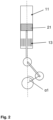
- Figure 2 schematically shows a view of a piston 21 in a cylinder 11 with a first crank angle ⁇ 1.
- the pressure within the cylinder 11 above the piston equalizes the scavenge pressure in the scavenge air receiver 19 during the expansion phase (blowback cut angle).
- the first position where pressures at the two locations are equal is the blowback cut angle.
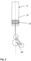
- Figure 3 schematically shows a view of a piston 21 in a cylinder 11 with a second crank angle ⁇ 2, which is the inlet ports opening angle (IPO angle).
- the second crank angle ⁇ 2 thus is the crank angle at which the piston 21 reaches the top of the inlet ports 13 during the descending phase.
- the blowback margin is the difference between the first crank angle ⁇ 1 when the pressure within the cylinder equalizes the scavenge pressure and the second crank angle ⁇ 2.
Landscapes
- Engineering & Computer Science (AREA)
- Chemical & Material Sciences (AREA)
- Combustion & Propulsion (AREA)
- Mechanical Engineering (AREA)
- General Engineering & Computer Science (AREA)
- Output Control And Ontrol Of Special Type Engine (AREA)
Priority Applications (1)
| Application Number | Priority Date | Filing Date | Title |
|---|---|---|---|
| EP23163611.9A EP4435246A1 (fr) | 2023-03-23 | 2023-03-23 | Moteur à combustion interne |
Applications Claiming Priority (1)
| Application Number | Priority Date | Filing Date | Title |
|---|---|---|---|
| EP23163611.9A EP4435246A1 (fr) | 2023-03-23 | 2023-03-23 | Moteur à combustion interne |
Publications (1)
| Publication Number | Publication Date |
|---|---|
| EP4435246A1 true EP4435246A1 (fr) | 2024-09-25 |
Family
ID=85726168
Family Applications (1)
| Application Number | Title | Priority Date | Filing Date |
|---|---|---|---|
| EP23163611.9A Withdrawn EP4435246A1 (fr) | 2023-03-23 | 2023-03-23 | Moteur à combustion interne |
Country Status (1)
| Country | Link |
|---|---|
| EP (1) | EP4435246A1 (fr) |
Citations (5)
| Publication number | Priority date | Publication date | Assignee | Title |
|---|---|---|---|---|
| US20040139949A1 (en) * | 2002-09-19 | 2004-07-22 | Nissan Motor Co., Ltd. | Internal exhaust gas recirculation amount estimation system of internal combustion engines |
| JP2006183480A (ja) | 2004-12-27 | 2006-07-13 | Nissan Motor Co Ltd | ユニフロー2ストローク内燃機関 |
| EP3095993A1 (fr) * | 2015-05-19 | 2016-11-23 | Winterthur Gas & Diesel AG | Procede de fonctionnement d'un gros moteur diesel, utilisation d'un tel procede et gros moteur diesel |
| WO2019150172A1 (fr) * | 2018-02-05 | 2019-08-08 | Wärtsilä Services Switzerland Ltd | Moteur à deux temps et procédé de fonctionnement du moteur |
| DK180717B1 (en) | 2019-11-15 | 2022-01-17 | Man Energy Solutions Filial Af Man Energy Solutions Se Tyskland | A large low speed turbocharged two-stroke uniflow scavenge internal combustion engine with crossheads |
-
2023
- 2023-03-23 EP EP23163611.9A patent/EP4435246A1/fr not_active Withdrawn
Patent Citations (5)
| Publication number | Priority date | Publication date | Assignee | Title |
|---|---|---|---|---|
| US20040139949A1 (en) * | 2002-09-19 | 2004-07-22 | Nissan Motor Co., Ltd. | Internal exhaust gas recirculation amount estimation system of internal combustion engines |
| JP2006183480A (ja) | 2004-12-27 | 2006-07-13 | Nissan Motor Co Ltd | ユニフロー2ストローク内燃機関 |
| EP3095993A1 (fr) * | 2015-05-19 | 2016-11-23 | Winterthur Gas & Diesel AG | Procede de fonctionnement d'un gros moteur diesel, utilisation d'un tel procede et gros moteur diesel |
| WO2019150172A1 (fr) * | 2018-02-05 | 2019-08-08 | Wärtsilä Services Switzerland Ltd | Moteur à deux temps et procédé de fonctionnement du moteur |
| DK180717B1 (en) | 2019-11-15 | 2022-01-17 | Man Energy Solutions Filial Af Man Energy Solutions Se Tyskland | A large low speed turbocharged two-stroke uniflow scavenge internal combustion engine with crossheads |
Similar Documents
| Publication | Publication Date | Title |
|---|---|---|
| JP7486998B2 (ja) | 内燃機関 | |
| US6209516B1 (en) | Control system and control method for diesel engine | |
| US20140032084A1 (en) | Temperature-Controlled Combustion System and Method | |
| US12338763B2 (en) | Hydrogen opposed-piston engine | |
| WO2014018351A1 (fr) | Moteur à allumage par compression à réactivité commandée, à recirculation des gaz d'échappement | |
| EP4227505B1 (fr) | Moteur à combustion interne et procédé de fonctionnement | |
| EP3109444B1 (fr) | Procédé de fonctionnement à faible charge pour faire fonctionner un moteur à combustion interne à piston alternatif, ainsi que moteur correspondant | |
| US11898448B2 (en) | Hydrogen-powered opposed-piston engine | |
| TW201425717A (zh) | 分別控制各汽缸燃燒要素的方法和內燃機 | |
| EP3983662B1 (fr) | Procédé d'actionnement de moteur à pistons et système de commande pour moteur à pistons | |
| EP4435246A1 (fr) | Moteur à combustion interne | |
| DK181214B1 (en) | A large two-stroke uniflow scavenged gaseous fueled engine and method for controlling supply of liquid fuel | |
| EP4219922A1 (fr) | Dispositif et procédé de fonctionnement d'un grand moteur | |
| EP4144974A1 (fr) | Procédé de fonctionnement d'un gros moteur et gros moteur | |
| KR102734506B1 (ko) | 대형 엔진을 작동시키기 위한 방법 및 대형 엔진 | |
| JP7521139B1 (ja) | 大型ターボ過給式2ストロークユニフロークロスヘッド内燃機関及びその動作方法 | |
| KR102798320B1 (ko) | 대형 엔진을 작동시키기 위한 방법 및 대형 엔진 | |
| DK202170475A1 (en) | A large two-stroke uniflow scavenged engine and method for operating cylinders selectively according to the pre-mix process or the compression-ignition process | |
| WO2016046449A1 (fr) | Procédé d'actionnement d'un moteur à pistons à combustion interne |
Legal Events
| Date | Code | Title | Description |
|---|---|---|---|
| PUAI | Public reference made under article 153(3) epc to a published international application that has entered the european phase |
Free format text: ORIGINAL CODE: 0009012 |
|
| STAA | Information on the status of an ep patent application or granted ep patent |
Free format text: STATUS: THE APPLICATION HAS BEEN PUBLISHED |
|
| AK | Designated contracting states |
Kind code of ref document: A1 Designated state(s): AL AT BE BG CH CY CZ DE DK EE ES FI FR GB GR HR HU IE IS IT LI LT LU LV MC ME MK MT NL NO PL PT RO RS SE SI SK SM TR |
|
| STAA | Information on the status of an ep patent application or granted ep patent |
Free format text: STATUS: THE APPLICATION IS DEEMED TO BE WITHDRAWN |
|
| 18D | Application deemed to be withdrawn |
Effective date: 20250326 |