EP4435307A2 - Tuyau en matière plastique et manchon en matière plastique pour la connexion avec un tel tuyau en matière plastique - Google Patents
Tuyau en matière plastique et manchon en matière plastique pour la connexion avec un tel tuyau en matière plastique Download PDFInfo
- Publication number
- EP4435307A2 EP4435307A2 EP24162084.8A EP24162084A EP4435307A2 EP 4435307 A2 EP4435307 A2 EP 4435307A2 EP 24162084 A EP24162084 A EP 24162084A EP 4435307 A2 EP4435307 A2 EP 4435307A2
- Authority
- EP
- European Patent Office
- Prior art keywords
- pipe
- plastic
- sleeve
- twisting
- plastic pipe
- Prior art date
- Legal status (The legal status is an assumption and is not a legal conclusion. Google has not performed a legal analysis and makes no representation as to the accuracy of the status listed.)
- Pending
Links
Images



Classifications
-
- F—MECHANICAL ENGINEERING; LIGHTING; HEATING; WEAPONS; BLASTING
- F16—ENGINEERING ELEMENTS AND UNITS; GENERAL MEASURES FOR PRODUCING AND MAINTAINING EFFECTIVE FUNCTIONING OF MACHINES OR INSTALLATIONS; THERMAL INSULATION IN GENERAL
- F16L—PIPES; JOINTS OR FITTINGS FOR PIPES; SUPPORTS FOR PIPES, CABLES OR PROTECTIVE TUBING; MEANS FOR THERMAL INSULATION IN GENERAL
- F16L9/00—Rigid pipes
- F16L9/12—Rigid pipes of plastics with or without reinforcement
-
- F—MECHANICAL ENGINEERING; LIGHTING; HEATING; WEAPONS; BLASTING
- F16—ENGINEERING ELEMENTS AND UNITS; GENERAL MEASURES FOR PRODUCING AND MAINTAINING EFFECTIVE FUNCTIONING OF MACHINES OR INSTALLATIONS; THERMAL INSULATION IN GENERAL
- F16L—PIPES; JOINTS OR FITTINGS FOR PIPES; SUPPORTS FOR PIPES, CABLES OR PROTECTIVE TUBING; MEANS FOR THERMAL INSULATION IN GENERAL
- F16L25/00—Construction or details of pipe joints not provided for in, or of interest apart from, groups F16L13/00 - F16L23/00
- F16L25/0036—Joints for corrugated pipes
-
- B—PERFORMING OPERATIONS; TRANSPORTING
- B29—WORKING OF PLASTICS; WORKING OF SUBSTANCES IN A PLASTIC STATE IN GENERAL
- B29C—SHAPING OR JOINING OF PLASTICS; SHAPING OF MATERIAL IN A PLASTIC STATE, NOT OTHERWISE PROVIDED FOR; AFTER-TREATMENT OF THE SHAPED PRODUCTS, e.g. REPAIRING
- B29C48/00—Extrusion moulding, i.e. expressing the moulding material through a die or nozzle which imparts the desired form; Apparatus therefor
- B29C48/03—Extrusion moulding, i.e. expressing the moulding material through a die or nozzle which imparts the desired form; Apparatus therefor characterised by the shape of the extruded material at extrusion
- B29C48/09—Articles with cross-sections having partially or fully enclosed cavities, e.g. pipes or channels
-
- B—PERFORMING OPERATIONS; TRANSPORTING
- B29—WORKING OF PLASTICS; WORKING OF SUBSTANCES IN A PLASTIC STATE IN GENERAL
- B29C—SHAPING OR JOINING OF PLASTICS; SHAPING OF MATERIAL IN A PLASTIC STATE, NOT OTHERWISE PROVIDED FOR; AFTER-TREATMENT OF THE SHAPED PRODUCTS, e.g. REPAIRING
- B29C48/00—Extrusion moulding, i.e. expressing the moulding material through a die or nozzle which imparts the desired form; Apparatus therefor
- B29C48/03—Extrusion moulding, i.e. expressing the moulding material through a die or nozzle which imparts the desired form; Apparatus therefor characterised by the shape of the extruded material at extrusion
- B29C48/13—Articles with a cross-section varying in the longitudinal direction, e.g. corrugated pipes
-
- B—PERFORMING OPERATIONS; TRANSPORTING
- B29—WORKING OF PLASTICS; WORKING OF SUBSTANCES IN A PLASTIC STATE IN GENERAL
- B29C—SHAPING OR JOINING OF PLASTICS; SHAPING OF MATERIAL IN A PLASTIC STATE, NOT OTHERWISE PROVIDED FOR; AFTER-TREATMENT OF THE SHAPED PRODUCTS, e.g. REPAIRING
- B29C48/00—Extrusion moulding, i.e. expressing the moulding material through a die or nozzle which imparts the desired form; Apparatus therefor
- B29C48/16—Articles comprising two or more components, e.g. co-extruded layers
- B29C48/18—Articles comprising two or more components, e.g. co-extruded layers the components being layers
- B29C48/21—Articles comprising two or more components, e.g. co-extruded layers the components being layers the layers being joined at their surfaces
-
- B—PERFORMING OPERATIONS; TRANSPORTING
- B29—WORKING OF PLASTICS; WORKING OF SUBSTANCES IN A PLASTIC STATE IN GENERAL
- B29C—SHAPING OR JOINING OF PLASTICS; SHAPING OF MATERIAL IN A PLASTIC STATE, NOT OTHERWISE PROVIDED FOR; AFTER-TREATMENT OF THE SHAPED PRODUCTS, e.g. REPAIRING
- B29C48/00—Extrusion moulding, i.e. expressing the moulding material through a die or nozzle which imparts the desired form; Apparatus therefor
- B29C48/25—Component parts, details or accessories; Auxiliary operations
- B29C48/30—Extrusion nozzles or dies
- B29C48/303—Extrusion nozzles or dies using dies or die parts movable in a closed circuit, e.g. mounted on movable endless support
-
- B—PERFORMING OPERATIONS; TRANSPORTING
- B29—WORKING OF PLASTICS; WORKING OF SUBSTANCES IN A PLASTIC STATE IN GENERAL
- B29C—SHAPING OR JOINING OF PLASTICS; SHAPING OF MATERIAL IN A PLASTIC STATE, NOT OTHERWISE PROVIDED FOR; AFTER-TREATMENT OF THE SHAPED PRODUCTS, e.g. REPAIRING
- B29C48/00—Extrusion moulding, i.e. expressing the moulding material through a die or nozzle which imparts the desired form; Apparatus therefor
- B29C48/25—Component parts, details or accessories; Auxiliary operations
- B29C48/36—Means for plasticising or homogenising the moulding material or forcing it through the nozzle or die
- B29C48/49—Means for plasticising or homogenising the moulding material or forcing it through the nozzle or die using two or more extruders to feed one die or nozzle
-
- F—MECHANICAL ENGINEERING; LIGHTING; HEATING; WEAPONS; BLASTING
- F16—ENGINEERING ELEMENTS AND UNITS; GENERAL MEASURES FOR PRODUCING AND MAINTAINING EFFECTIVE FUNCTIONING OF MACHINES OR INSTALLATIONS; THERMAL INSULATION IN GENERAL
- F16L—PIPES; JOINTS OR FITTINGS FOR PIPES; SUPPORTS FOR PIPES, CABLES OR PROTECTIVE TUBING; MEANS FOR THERMAL INSULATION IN GENERAL
- F16L11/00—Hoses, i.e. flexible pipes
- F16L11/04—Hoses, i.e. flexible pipes made of rubber or flexible plastics
- F16L11/11—Hoses, i.e. flexible pipes made of rubber or flexible plastics with corrugated wall
- F16L11/118—Hoses, i.e. flexible pipes made of rubber or flexible plastics with corrugated wall having arrangements for particular purposes, e.g. electrically conducting
-
- F—MECHANICAL ENGINEERING; LIGHTING; HEATING; WEAPONS; BLASTING
- F16—ENGINEERING ELEMENTS AND UNITS; GENERAL MEASURES FOR PRODUCING AND MAINTAINING EFFECTIVE FUNCTIONING OF MACHINES OR INSTALLATIONS; THERMAL INSULATION IN GENERAL
- F16L—PIPES; JOINTS OR FITTINGS FOR PIPES; SUPPORTS FOR PIPES, CABLES OR PROTECTIVE TUBING; MEANS FOR THERMAL INSULATION IN GENERAL
- F16L11/00—Hoses, i.e. flexible pipes
- F16L11/04—Hoses, i.e. flexible pipes made of rubber or flexible plastics
- F16L11/12—Hoses, i.e. flexible pipes made of rubber or flexible plastics with arrangements for particular purposes, e.g. specially profiled, with protecting layer, heated, electrically conducting
- F16L11/121—Hoses, i.e. flexible pipes made of rubber or flexible plastics with arrangements for particular purposes, e.g. specially profiled, with protecting layer, heated, electrically conducting specially profiled cross sections
-
- F—MECHANICAL ENGINEERING; LIGHTING; HEATING; WEAPONS; BLASTING
- F16—ENGINEERING ELEMENTS AND UNITS; GENERAL MEASURES FOR PRODUCING AND MAINTAINING EFFECTIVE FUNCTIONING OF MACHINES OR INSTALLATIONS; THERMAL INSULATION IN GENERAL
- F16L—PIPES; JOINTS OR FITTINGS FOR PIPES; SUPPORTS FOR PIPES, CABLES OR PROTECTIVE TUBING; MEANS FOR THERMAL INSULATION IN GENERAL
- F16L11/00—Hoses, i.e. flexible pipes
- F16L11/22—Multi-channel hoses
-
- H—ELECTRICITY
- H02—GENERATION; CONVERSION OR DISTRIBUTION OF ELECTRIC POWER
- H02G—INSTALLATION OF ELECTRIC CABLES OR LINES, OR OF COMBINED OPTICAL AND ELECTRIC CABLES OR LINES
- H02G3/00—Installations of electric cables or lines or protective tubing therefor in or on buildings, equivalent structures or vehicles
- H02G3/02—Details
- H02G3/04—Protective tubing or conduits, e.g. cable ladders or cable troughs
- H02G3/0462—Tubings, i.e. having a closed section
- H02G3/0468—Corrugated
-
- H—ELECTRICITY
- H02—GENERATION; CONVERSION OR DISTRIBUTION OF ELECTRIC POWER
- H02G—INSTALLATION OF ELECTRIC CABLES OR LINES, OR OF COMBINED OPTICAL AND ELECTRIC CABLES OR LINES
- H02G3/00—Installations of electric cables or lines or protective tubing therefor in or on buildings, equivalent structures or vehicles
- H02G3/02—Details
- H02G3/06—Joints for connecting lengths of protective tubing or channels, to each other or to casings, e.g. to distribution boxes; Ensuring electrical continuity in the joint
-
- B—PERFORMING OPERATIONS; TRANSPORTING
- B29—WORKING OF PLASTICS; WORKING OF SUBSTANCES IN A PLASTIC STATE IN GENERAL
- B29C—SHAPING OR JOINING OF PLASTICS; SHAPING OF MATERIAL IN A PLASTIC STATE, NOT OTHERWISE PROVIDED FOR; AFTER-TREATMENT OF THE SHAPED PRODUCTS, e.g. REPAIRING
- B29C48/00—Extrusion moulding, i.e. expressing the moulding material through a die or nozzle which imparts the desired form; Apparatus therefor
- B29C48/25—Component parts, details or accessories; Auxiliary operations
- B29C48/30—Extrusion nozzles or dies
- B29C48/32—Extrusion nozzles or dies with annular openings, e.g. for forming tubular articles
-
- B—PERFORMING OPERATIONS; TRANSPORTING
- B29—WORKING OF PLASTICS; WORKING OF SUBSTANCES IN A PLASTIC STATE IN GENERAL
- B29C—SHAPING OR JOINING OF PLASTICS; SHAPING OF MATERIAL IN A PLASTIC STATE, NOT OTHERWISE PROVIDED FOR; AFTER-TREATMENT OF THE SHAPED PRODUCTS, e.g. REPAIRING
- B29C48/00—Extrusion moulding, i.e. expressing the moulding material through a die or nozzle which imparts the desired form; Apparatus therefor
- B29C48/25—Component parts, details or accessories; Auxiliary operations
- B29C48/78—Thermal treatment of the extrusion moulding material or of preformed parts or layers, e.g. by heating or cooling
- B29C48/86—Thermal treatment of the extrusion moulding material or of preformed parts or layers, e.g. by heating or cooling at the nozzle zone
-
- B—PERFORMING OPERATIONS; TRANSPORTING
- B29—WORKING OF PLASTICS; WORKING OF SUBSTANCES IN A PLASTIC STATE IN GENERAL
- B29C—SHAPING OR JOINING OF PLASTICS; SHAPING OF MATERIAL IN A PLASTIC STATE, NOT OTHERWISE PROVIDED FOR; AFTER-TREATMENT OF THE SHAPED PRODUCTS, e.g. REPAIRING
- B29C48/00—Extrusion moulding, i.e. expressing the moulding material through a die or nozzle which imparts the desired form; Apparatus therefor
- B29C48/25—Component parts, details or accessories; Auxiliary operations
- B29C48/78—Thermal treatment of the extrusion moulding material or of preformed parts or layers, e.g. by heating or cooling
- B29C48/86—Thermal treatment of the extrusion moulding material or of preformed parts or layers, e.g. by heating or cooling at the nozzle zone
- B29C48/87—Cooling
-
- F—MECHANICAL ENGINEERING; LIGHTING; HEATING; WEAPONS; BLASTING
- F16—ENGINEERING ELEMENTS AND UNITS; GENERAL MEASURES FOR PRODUCING AND MAINTAINING EFFECTIVE FUNCTIONING OF MACHINES OR INSTALLATIONS; THERMAL INSULATION IN GENERAL
- F16L—PIPES; JOINTS OR FITTINGS FOR PIPES; SUPPORTS FOR PIPES, CABLES OR PROTECTIVE TUBING; MEANS FOR THERMAL INSULATION IN GENERAL
- F16L21/00—Joints with sleeve or socket
- F16L21/02—Joints with sleeve or socket with elastic sealing rings between pipe and sleeve or between pipe and socket, e.g. with rolling or other prefabricated profiled rings
- F16L21/035—Joints with sleeve or socket with elastic sealing rings between pipe and sleeve or between pipe and socket, e.g. with rolling or other prefabricated profiled rings placed around the spigot end before connection
-
- F—MECHANICAL ENGINEERING; LIGHTING; HEATING; WEAPONS; BLASTING
- F16—ENGINEERING ELEMENTS AND UNITS; GENERAL MEASURES FOR PRODUCING AND MAINTAINING EFFECTIVE FUNCTIONING OF MACHINES OR INSTALLATIONS; THERMAL INSULATION IN GENERAL
- F16L—PIPES; JOINTS OR FITTINGS FOR PIPES; SUPPORTS FOR PIPES, CABLES OR PROTECTIVE TUBING; MEANS FOR THERMAL INSULATION IN GENERAL
- F16L25/00—Construction or details of pipe joints not provided for in, or of interest apart from, groups F16L13/00 - F16L23/00
- F16L25/0036—Joints for corrugated pipes
- F16L25/0054—Joints for corrugated pipes with specially shaped sealing rings
Definitions
- the invention relates to a plastic pipe and a plastic sleeve for connecting to such a plastic pipe.
- EN 10 2013 109 111 A1 reveals a tube with multiple lumens.
- EP 2 960 387 A1 reveals a pipe connection kit.
- US$5,305,797 discloses a kit for tubular elements.
- Pipes with internal chambers are used for water treatment in sewage technology or as cable protection pipes, for example.
- the pipes When connecting pipes with multiple channels axially, the pipes must be precisely positioned to ensure the functionality of the multiple channels.
- So-called apex markings are printed on drainage pipes or are applied as colored stripes, for example in the Extrusion of composite pipes. The apex markings enable pipes to be arranged one behind the other at an exact angle, but cannot prevent faulty assembly as a result of inaccurate working methods.
- the invention is based on the object of improving the angle-accurate axial connection of plastic pipes with multiple channels and, in particular, of implementing it in a fail-safe manner.
- a connection of plastic pipes arranged axially one behind the other with an accurate angle of rotation in the circumferential direction with respect to a longitudinal pipe axis can be carried out in a fail-safe manner if a plastic pipe has an anti-twisting element.
- the anti-twisting element is attached to elevations arranged on the outside of the pipe.
- the elevations are waves or ribs that are oriented perpendicular to the longitudinal pipe axis.
- the anti-twisting element guarantees mechanical protection against twisting for the plastic pipe.
- the anti-twisting element is arranged eccentrically with respect to the longitudinal pipe axis in a plane perpendicular to the longitudinal pipe axis.
- the anti-twisting element has a radial distance from the longitudinal pipe axis in the plane oriented perpendicular to the longitudinal pipe axis.
- the anti-twisting element extends parallel to the longitudinal pipe axis, i.e. is axially oriented.
- At least one elevation has the anti-twisting element.
- the anti-twisting element is arranged in relation to the longitudinal axis of the pipe at an axial position at which an anti-twisting element is also arranged.
- the plastic pipe has a rotationally symmetrical outer contour in elevation-free areas, i.e. in particular in areas that are formed axially between two adjacent elevations.
- the axial intermediate area is designed without an anti-twisting element.
- the anti-twisting element has an axial length that is in particular greater than an axial distance between two axially adjacent elevations. This means that several, in particular at least two, axially adjacent elevations have the anti-twisting element.
- a plastic sleeve according to the invention has an anti-twist counter element that corresponds to the anti-twist element of the plastic pipe.
- the plastic pipe is clearly fixed in a rotational angle position with respect to the longitudinal axis of the pipe by means of the anti-twist element on the anti-twist counter element of the plastic sleeve.
- An unintentionally twisted and/or inaccurate arrangement of the plastic pipes relative to one another in the circumferential direction with respect to the longitudinal axis of the pipe is reliably excluded.
- the connection of the plastic pipes is fail-safe.
- the plastic pipe and the plastic sleeve according to the invention enable an axial connection to one another according to a tongue and groove principle.
- This connection technology is uncomplicated, mechanically robust and intuitive to use.
- the multiple channels are chambers in the interior of the plastic pipe.
- the chambers each extend axially, i.e. along the longitudinal axis of the pipe.
- the chambers are separated from one another in particular by at least one separating element in the interior of the pipe.
- a plastic pipe according to claim 2 enables uncomplicated production.
- the anti-twisting element extends in particular in the radial direction with respect to the longitudinal axis of the pipe, in particular as a radial depression, in particular as an external groove, or as a radial elevation, in particular in the form of an external web.
- the anti-twisting element is immediately perceptible visually and haptically.
- a plastic pipe according to claim 3 enables uncomplicated production, in particular in the extrusion process. Because the anti-twisting element is formed in one piece, it is mechanically robust. The anti-twisting element is integrally formed. Additional production steps are not required.
- a plastic pipe according to claim 4 ensures a stable connection technology.
- the anti-twisting element extends along the entire length of the plastic pipe. The production is particularly uncomplicated and can be carried out continuously.
- An embodiment of the anti-twisting element according to claim 5 simplifies the axial connection with the plastic sleeve.
- the design of the anti-twisting element according to claim 6 avoids stress peaks in the plastic material and/or defects caused by manufacturing.
- the design of a plastic pipe according to claim 7 enables a wide range of applications, particularly in the field of wastewater technology.
- a plastic pipe according to claim 8 simplifies the production of the multiple channels.
- At least one separating element can be held, in particular detachably held, on at least one guide element that is arranged on the inside of the pipe.
- the separating element can in particular be pushed axially into the pipe.
- the separating element can be removed from the pipe again. Assembly and/or disassembly of the plastic pipe with separating element are simplified and inexpensive.
- the separating element can be removed from the plastic pipe without causing any damage.
- the at least one guide element is integrally formed on the inside of the pipe.
- the guide element and anti-twisting element are arranged at different rotation angle positions in the circumferential direction around the longitudinal axis of the pipe, in particular with a rotation angle offset of 90°.
- a rotation angle offset of 90°.
- Another rotation angle offset or no rotation angle offset can also be selected.
- a plastic sleeve according to claim 9 ensures the inventive fail-safe positioning with respect to the plastic pipe and enables the fail-safe connection with the plastic pipe.
- the plastic sleeve has an axial stop element to which the plastic pipe is axially fixed in the plastic sleeve, in particular by axial contact.
- the axial stop element is a contact shoulder.
- the axial stop element is followed by a socket pipe section which can be cylindrical and/or conical with respect to a socket longitudinal axis, wherein a conicity angle is small and in particular less than 5°, in particular less than 3° and in particular less than 1°.
- the plastic sleeve has an insertion opening into which the plastic pipe is inserted.
- a widening insertion section is arranged towards the insertion opening. It is important that the anti-twist counter element is arranged on an inner wall of the sleeve pipe section and thus ensures that the plastic pipe is arranged in an anti-twist manner.
- the anti-twisting counter element has an axial length that is greater than an axial distance between two adjacent elevations on the plastic pipe. This means that when the plastic pipe is coupled to the plastic sleeve, the anti-twisting counter element interacts with at least two axially adjacent elevations, in particular their anti-twisting elements. In particular, the anti-twisting counter element engages in the anti-twisting element in the radial direction or vice versa.
- a plastic sleeve according to claim 10 ensures a sealing of the plastic pipe in the plastic sleeve. It was recognized that a Sealing section, which is arranged along the socket longitudinal axis between the axial stop element and the socket pipe section, can be designed without anti-twisting counter element, in particular cylindrical. A profile sealing ring can be arranged in the sealing section in a reliable and sealing manner.
- a plastic sleeve according to claim 11 or 12 enables various advantageous connection techniques.
- An arrangement according to claim 13 has the advantages of the plastic pipe and the plastic sleeve, to which reference is hereby made.
- the plastic pipe is arranged with the pipe longitudinal axis coaxial with the sleeve longitudinal axis of the plastic sleeve.
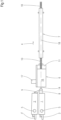
- the device shown for producing composite pipes has two extruders 1, 2. These are each driven by a speed-adjustable drive motor 3, 3' which - with respect to a conveying direction 4 of the entire device - is provided upstream of feed hoppers 5 of the extruders 1, 2.
- a cross-spray head 8 is attached to an extruder 1 arranged in alignment with the molding machine 6 and the post-cooling device 7 and projects into the molding machine 6.
- the other extruder 2 arranged to the side of this extruder 1 is connected to the cross-spray head 8 via an injection channel 9 which opens laterally into the cross-spray head 8.
- a composite pipe 10 is formed in the forming machine 6, which exits the forming machine 6 in the conveying direction 4 and is cooled in the post-cooling device 7. Behind this post-cooling device 7 it can then be cut into pieces of suitable length.
- the forming machine 6 is known in its construction and is described, for example, in EP 0 563 575 A2 described, to which explicit reference is made.
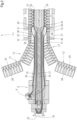
- the transverse injection head 8 has two melt channels arranged concentrically to a common central longitudinal axis 18, namely an inner melt channel 19 and an outer melt channel 20, which - with respect to the conveying direction 4 - end downstream in an inner nozzle 21 and an outer nozzle 22, respectively.
- the inner melt channel 19 is connected to an injection channel 23 of the extruder 1 arranged in alignment with the molding machine 6, whereas the outer melt channel 20 is connected to the injection channel 9 of the other extruder 2.
- a calibration mandrel 24 is attached to the latter, which also runs concentrically to the central longitudinal axis 18. It has cooling channels 25 for cooling medium, in particular cooling water, which is supplied via a cooling water feed line 26 and discharged via a cooling water return line 27.
- the lines 26, 27 can be guided through an approximately tubular supply channel formed concentrically to the central longitudinal axis 18 in the spray head 8.
- the half-moulds 12, 12' have ring-shaped mould recesses 28 which are arranged one behind the other at regular intervals and which are each connected to partial vacuum channels 29.
- the partial vacuum channels 29 - as Fig. 2 can be removed - to partial vacuum supply sources 30, 31, so that the mold recesses 28 are subjected to partial vacuum.
- Plastic melt is fed from the extruder 1 through the injection channel 23 to the transverse injection head 8 and flows through the inner melt channel 19 to the inner nozzle 21 and exits there as an inner tube 34, which reaches the calibration mandrel 24. This expands slightly outwards from the inner nozzle 21 in the conveying direction 4 until the inner tube 34 reaches the corrugation troughs 35 of the outer tube 32 and is welded to it.
- the inner tube 34 and the outer tube 32 form a pipe base body of the composite pipe 10.
- the composite pipe 10 has a longitudinal pipe axis 15.
- the inner pipe 34 is welded to the outer pipe 32 in the area of the corrugation troughs 35.
- the transverse grooves are perpendicular elevations 33 oriented towards the longitudinal pipe axis 15.
- the outer pipe 32 forms a pipe outer side of the composite pipe 10.
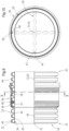
- the inner pipe 34 is cylindrical with respect to the longitudinal pipe axis 15 with a substantially smooth pipe inner side 43.
- the inner tube 34 has an integrally formed, i.e. one-piece, guide element 44 on the inner tube side 43.
- the contour of the guide element 44 can be produced in particular by means of a mold structure of the calibration mandrel 24 (not shown in detail) in the extrusion process.
- the contour of the guide element 44 corresponds to the contour of the mold structure on the calibration mandrel 24.
- the guide element 44 extends parallel to the longitudinal tube axis 15.
- the guide element 44 is axially oriented.
- the guide element 44 forms a guide web or a guide rail.
- the guide element 44 projects into the pipe interior enclosed by the pipe base body, in particular in the radial direction with respect to the pipe longitudinal axis 15, with a first height h 1 which is at least 1.0% of the inner diameter d i of the inner pipe 34.
- the separating element 45 is held in place by a separating element 45 shown in dashed lines.
- the separating element 45 is designed as a cross profile and is arranged concentrically to the longitudinal axis 15 of the pipe.
- the separating element 45 has two intersecting webs 46 which are connected centrally and in one piece.
- the separating element 45 can also have a different profile shape and in particular be designed in the form of a plate. It can be advantageous if several guide elements 44 are arranged along the inner circumference of the inner side 43 of the pipe in order to improve the holding of the separating element.
- the web 46 facing the guide element 44 has a front side contour 47 corresponding to the guide element 44, with which the separating element 45 can be inserted into the inner pipe 34 and is held on the guide element 44.
- the separating element 45 is held in the composite pipe 10 in a twist-proof manner and at an exact angle with respect to the pipe's longitudinal axis 15.
- the separating element 45 divides the pipe interior of the composite pipe 10 into four, in particular equally sized, sub-channels 48.
- the sub-channels 48 are also referred to as multiple channels.
- the guide element 44 guarantees that the separating element 45 is secured against twisting with respect to the pipe's longitudinal axis 15.
- the separating element 45 is supported on the pipe's inner side 43 by the three remaining front sides of the webs 46.
- the separating element 45 is arranged robustly in the pipe base body. An unintentional change in the rotational position of the separating element 45 with respect to the pipe longitudinal axis 15 is reliably prevented.
- An anti-twisting element 49 in the form of an external groove is formed on the elevations 33 on the outer pipe 32.
- the anti-twisting element 49 forms a radial depression with respect to the pipe longitudinal axis 15.
- the anti-twisting element 49 is arranged eccentrically with respect to the pipe longitudinal axis 15 with a radial distance from the pipe longitudinal axis 15.
- the anti-twisting element 49 is designed along several elevations 33.
- the anti-twisting element 49 extends in the axial direction starting from a first pipe end 50, in particular continuously to an opposite second pipe end 51 or to the pipe sleeve 36 formed on the composite pipe 10.
- the anti-twisting element 49 can be designed as a web in an embodiment not shown. Accordingly, the elevations 33 in the area of the anti-twisting element are raised radially with respect to the longitudinal axis 15 of the pipe.
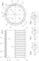
- the outer groove has a groove depth trr and a groove width b N.
- the groove depth trr is approximately half the groove width b N .
- trr 1.0 xb N ...3.0 xb N .
- the corners of the groove cross-section are rounded with curvature radii r.
- a uniform curvature radius r is used, which is in particular at least 2.0 mm.
- the groove cross-section of the anti-twisting element 49' is semi-circular, with the groove depth trr ⁇ being approximately half the groove width brr ⁇ .
- the groove depth t N " is comparatively larger and is between 50% and 100% of the groove width b N ".
- An opening angle ⁇ of the V-shape is between 30° and 90°, in particular between 45° and 75° and in particular 60°.
- the half-molds 12, 12' are designed such that pipe sleeves 36 are formed at predetermined intervals within the endlessly produced composite pipe 10.
- a substantially cylindrical sleeve recess 37 is formed in a pair of half-molds 12, 12', which thus has a substantially smooth, cylindrical wall 38.
- a transition section 39 is formed between the wall 38 of the sleeve recess 37 and the mold recess 28 leading in the conveying direction 4.
- the end of the wall 38 of the sleeve recess 37 trailing - in the conveying direction 4 - is followed by a frustoconical mold section 40 in which an outwardly expanding inlet end 41 of the sleeve 36 is formed.
- This is in turn followed by a transition section 42 which leads to the next mold recess 28 trailing in the conveying direction 4.
- the plastic sleeve 36 is integrally formed on the composite pipe 10.
- the sleeve 36 is also referred to as a connecting sleeve.
- the sleeve 36 has a sleeve longitudinal axis 52 that coincides with the pipe longitudinal axis 15 of the integrally formed composite pipe 10.
- the sleeve 36 has an insertion opening 53 opposite the first pipe end 50, which is arranged as the open end of an insertion section 54 that widens towards the insertion opening 53.
- the insertion section 54 is designed to widen conically with respect to the sleeve longitudinal axis 52 with a half opening angle ⁇ between 10° and 25°.
- the insertion section 54 is followed first by a socket pipe section 55 and then by a sealing section 56.
- the socket pipe section 55 is cylindrical with respect to the socket longitudinal axis 52 and/or at least in sections slightly conically widening.
- An anti-twist counter element 58 is formed on an inner wall 57 of the socket pipe section 55 and is in particular formed in one piece on the socket pipe section 55.
- the anti-twisting counter element 58 is designed as a raised structure that protrudes from the inner wall 57 of the socket pipe section 55 in the radial direction with respect to the socket longitudinal axis 52.
- the anti-twisting counter element 58 is designed as a web that protrudes radially from the inner wall 57.
- the anti-twisting counter element 58 is designed with a rectangular profile cross-section that corresponds to the groove contour of the anti-twisting element 49 according to Fig. 5 and 6 corresponds.
- the external dimensions of the anti-twisting counter element 58 are slightly smaller than the internal dimensions of the anti-twisting element 49.
- the anti-twisting element 49 is arranged to fit precisely on the anti-twisting counter element 58.
- the anti-twisting counter element 58 is arranged eccentrically with respect to the sleeve longitudinal axis 52, i.e. in particular with a radial distance.
- the anti-twisting counter element 58 has an axial insertion bevel 61 facing the insertion opening 53.
- the anti-twisting counter element 58 has an axial length L that is greater than an axial distance D a between two adjacent elevations 33 of a corresponding plastic pipe 10. This ensures that the anti-twisting counter element 58 is arranged on the anti-twisting element 49 on two elevations 33 arranged adjacently in the axial direction.
- the anti-twisting device is therefore designed to be particularly robust mechanically.
- the sealing section 56 is designed without any anti-twisting counter element. This means in particular that the inner wall 57 in the area of the sealing section 56 is completely cylindrical.
- the sealing section 56 is followed by an extension section 59 which forms a diameter transition from the inner pipe 34 of the composite pipe 10 to the outer wall of the sleeve 36.
- the extension section 59 serves as an axial stop element for the sleeve 36.
- the axial stop element 59 determines a maximum axial insertion depth of the composite pipe 10 at the sleeve 36.
- another composite pipe 10' is axially inserted into the connecting sleeve 36.
- the composite pipe 10' has an anti-twist element 49 which corresponds to the anti-twist counter element 58 of the sleeve 36.
- the web-like anti-twist counter element 58 engages in the groove-shaped anti-twist element 49 and thus ensures reliable anti-twist protection of the composite pipe 10' relative to the composite pipe 10.
- a sealing element 60 in particular in the form of a profile sealing ring, between two elevations 33 of the composite pipe 10'.
- the sealing of the composite pipe 10' in the sleeve 36 is reliably ensured.
- the profile sealing ring 60 can reliably seal against the circular cylindrical smooth inner wall 57 in the area of the sealing section 56.
- the plastic pipe 10 can also be designed as a finned pipe with corresponding rib-shaped elevations.
- a finned pipe is made of EP 0 531 750 A2 and its production from DE 2450171 C2 known, to which explicit reference is made.
- the composite pipe 10' is in Fig. 11 shown separately. It differs from the composite pipe 10 according to Fig.3 in that no connecting sleeve is formed.
- the anti-twisting element 49 is designed to be completely axially continuous.
- a plastic sleeve 36' is used according to Fig. 12 and 13 , which is designed as a double plug-in sleeve.
- the double plug-in sleeve 36' has two insertion openings 53' arranged facing away from one another, corresponding insertion sections 54', sleeve pipe sections 55', sealing sections 56' and an axial stop element 59', which is arranged in particular axially centrally.
- the axial stop element 59' is designed as an inner web, which has a web height that is greater than the groove depth of the anti-twist elements 49.
- the axial stop element 59' forms an annular surface-shaped contact shoulder, which creates a reliable and stable axial lock for the composite pipes 10'.
- the axial stop element 59' is designed with a corresponding axial width, so that composite pipes 10' connected to the double plug-in sleeve 36' are connected to one another in abutting relationship at the end.
Landscapes
- Engineering & Computer Science (AREA)
- General Engineering & Computer Science (AREA)
- Mechanical Engineering (AREA)
- Architecture (AREA)
- Civil Engineering (AREA)
- Structural Engineering (AREA)
- Manufacturing & Machinery (AREA)
- Rigid Pipes And Flexible Pipes (AREA)
- Branch Pipes, Bends, And The Like (AREA)
Applications Claiming Priority (1)
| Application Number | Priority Date | Filing Date | Title |
|---|---|---|---|
| DE102023202512.4A DE102023202512A1 (de) | 2023-03-21 | 2023-03-21 | Kunststoffrohr und Kunststoffmuffe zum Verbinden mit einem derartigen Kunststoffrohr |
Publications (2)
| Publication Number | Publication Date |
|---|---|
| EP4435307A2 true EP4435307A2 (fr) | 2024-09-25 |
| EP4435307A3 EP4435307A3 (fr) | 2024-12-25 |
Family
ID=90363119
Family Applications (1)
| Application Number | Title | Priority Date | Filing Date |
|---|---|---|---|
| EP24162084.8A Pending EP4435307A3 (fr) | 2023-03-21 | 2024-03-07 | Tuyau en matière plastique et manchon en matière plastique pour la connexion avec un tel tuyau en matière plastique |
Country Status (4)
| Country | Link |
|---|---|
| US (1) | US20240318748A1 (fr) |
| EP (1) | EP4435307A3 (fr) |
| CA (1) | CA3233058A1 (fr) |
| DE (1) | DE102023202512A1 (fr) |
Families Citing this family (2)
| Publication number | Priority date | Publication date | Assignee | Title |
|---|---|---|---|---|
| DE102023202512A1 (de) | 2023-03-21 | 2024-09-26 | Ralph Peter Hegler | Kunststoffrohr und Kunststoffmuffe zum Verbinden mit einem derartigen Kunststoffrohr |
| DE102024203507A1 (de) * | 2024-04-16 | 2025-10-16 | Ralph Peter Hegler | Sedimentationsrohr und Rohrsedimentationsanlage mit einem derartigen Sedimentationsrohr |
Citations (11)
| Publication number | Priority date | Publication date | Assignee | Title |
|---|---|---|---|---|
| US3578777A (en) | 1969-06-11 | 1971-05-18 | Koppy Tool Corp | Corrugated tubing |
| DE2450171C2 (de) | 1973-10-22 | 1983-04-14 | Wendia Plast AB, Aange | Vorrichtung zum Herstellen von Rippenrohren |
| EP0531750A2 (fr) | 1991-09-07 | 1993-03-17 | Wilhelm Hegler | Procédé pour le soudage de tuyaux en matière thermoplastique |
| EP0563575A2 (fr) | 1992-03-31 | 1993-10-06 | Wilhelm Hegler | Procédé et dispositif de production en continu d'un tube composite avec manchon |
| US5305797A (en) | 1993-05-10 | 1994-04-26 | Roy Sr John D | Compartmented conduit tube construction |
| EP0995579A2 (fr) | 1998-10-21 | 2000-04-26 | Hegler, Ralph-Peter, Dr.-Ing. | Procédé de production en continu d'un tube composite avec manchon, et appareil pour la mise en oeuvre du procédé |
| US20060254663A1 (en) | 2000-06-30 | 2006-11-16 | Renaud Michel C | Variable stiffness bellows |
| DE102009056975B3 (de) | 2009-12-07 | 2011-05-19 | Viega Gmbh & Co. Kg | Rohrförmiges Bauteil |
| DE102013109111A1 (de) | 2012-08-28 | 2014-03-06 | General Electric Company | Schlauch mit mehreren Lumen |
| EP2960387A1 (fr) | 2014-06-27 | 2015-12-30 | Ralph Peter Hegler | Kit de liaison de tuyau |
| DE102023202512A1 (de) | 2023-03-21 | 2024-09-26 | Ralph Peter Hegler | Kunststoffrohr und Kunststoffmuffe zum Verbinden mit einem derartigen Kunststoffrohr |
Family Cites Families (5)
| Publication number | Priority date | Publication date | Assignee | Title |
|---|---|---|---|---|
| US3695643A (en) * | 1970-05-18 | 1972-10-03 | Hancock Brick & Tile Co | Corrugated tube coupling means |
| US3897090A (en) * | 1972-05-19 | 1975-07-29 | Plastic Tubing | Corrugated plastic pipe with integrally formed coupler |
| US3899198A (en) * | 1973-04-18 | 1975-08-12 | Ernest J Maroschak | Coupling for interconnecting corrugated plastic tubes |
| DE3744510A1 (de) * | 1987-12-30 | 1989-07-13 | Wilhelm Hegler | Rohrverbindungs-element |
| DE102014218372A1 (de) * | 2014-09-12 | 2016-03-17 | Ralph Peter Hegler | Inspektions- bzw. Revisions-Schacht aus Kunststoff |
-
2023
- 2023-03-21 DE DE102023202512.4A patent/DE102023202512A1/de active Pending
-
2024
- 2024-03-07 EP EP24162084.8A patent/EP4435307A3/fr active Pending
- 2024-03-19 CA CA3233058A patent/CA3233058A1/en active Pending
- 2024-03-21 US US18/612,139 patent/US20240318748A1/en active Pending
Patent Citations (11)
| Publication number | Priority date | Publication date | Assignee | Title |
|---|---|---|---|---|
| US3578777A (en) | 1969-06-11 | 1971-05-18 | Koppy Tool Corp | Corrugated tubing |
| DE2450171C2 (de) | 1973-10-22 | 1983-04-14 | Wendia Plast AB, Aange | Vorrichtung zum Herstellen von Rippenrohren |
| EP0531750A2 (fr) | 1991-09-07 | 1993-03-17 | Wilhelm Hegler | Procédé pour le soudage de tuyaux en matière thermoplastique |
| EP0563575A2 (fr) | 1992-03-31 | 1993-10-06 | Wilhelm Hegler | Procédé et dispositif de production en continu d'un tube composite avec manchon |
| US5305797A (en) | 1993-05-10 | 1994-04-26 | Roy Sr John D | Compartmented conduit tube construction |
| EP0995579A2 (fr) | 1998-10-21 | 2000-04-26 | Hegler, Ralph-Peter, Dr.-Ing. | Procédé de production en continu d'un tube composite avec manchon, et appareil pour la mise en oeuvre du procédé |
| US20060254663A1 (en) | 2000-06-30 | 2006-11-16 | Renaud Michel C | Variable stiffness bellows |
| DE102009056975B3 (de) | 2009-12-07 | 2011-05-19 | Viega Gmbh & Co. Kg | Rohrförmiges Bauteil |
| DE102013109111A1 (de) | 2012-08-28 | 2014-03-06 | General Electric Company | Schlauch mit mehreren Lumen |
| EP2960387A1 (fr) | 2014-06-27 | 2015-12-30 | Ralph Peter Hegler | Kit de liaison de tuyau |
| DE102023202512A1 (de) | 2023-03-21 | 2024-09-26 | Ralph Peter Hegler | Kunststoffrohr und Kunststoffmuffe zum Verbinden mit einem derartigen Kunststoffrohr |
Also Published As
| Publication number | Publication date |
|---|---|
| US20240318748A1 (en) | 2024-09-26 |
| EP4435307A3 (fr) | 2024-12-25 |
| CA3233058A1 (en) | 2025-06-23 |
| DE102023202512A1 (de) | 2024-09-26 |
Similar Documents
| Publication | Publication Date | Title |
|---|---|---|
| EP0890770B1 (fr) | Tube composite avec manchon intégrée et méthode pour sa fabrication | |
| EP0789176B1 (fr) | Tube composite avec manchon et procédé pour sa fabrication | |
| EP4435307A2 (fr) | Tuyau en matière plastique et manchon en matière plastique pour la connexion avec un tel tuyau en matière plastique | |
| EP2304300B1 (fr) | Manchon coulissant en plastique et raccord muni d'un tel manchon coulissant | |
| DE4210482A1 (de) | Verfahren und Vorrichtung zur fortlaufenden Herstellung eines Verbundrohres mit Rohr-Muffe | |
| EP0600214B1 (fr) | Procédé et dispositif pour la fabrication continue d'un tube composite comprenant une partie extérieuere essentiellement lisse | |
| EP3592526B1 (fr) | Tuyau à pression et procédé de fabrication d'un tuyau à pression | |
| EP1683624A2 (fr) | Manchon de calibrage réglable en continu destiné à des tuyaux en plastique | |
| DE3737588C3 (de) | Verfahren zum Herstellen eines innen glatten, außen gerippten Rohres aus extrudierbarem Kunststoff sowie Vorrichtung zur Durchführung des Verfahrens | |
| DE2446421C3 (de) | Spritzkopf zum Strangpressen von Hohlprofilen aus Kunststoff | |
| EP2452803B1 (fr) | Dispositif pour la fabrication des tubes thermoplastiques ondulées | |
| EP2065159A1 (fr) | Dispositif de fabrication continue d'un tuyau composite doté d'un manchon tubulaire | |
| EP4434716B1 (fr) | Tuyau en matière plastique | |
| EP1736299B1 (fr) | Dispositif pour fabriquer les tubes à double paroi | |
| EP3609672B1 (fr) | Connecteur enfichable en matière plastique et procédé de fabrication associé | |
| EP1911565A2 (fr) | Dispositif destiné à la fabrication de conduites composites | |
| DE102009060043B4 (de) | Vorrichtung zum Spritzgießen von Rohrteilen aus Kunststoff | |
| DE19941160A1 (de) | Zylinder für einen Schneckenextruder mit Kanälen für ein Temperiermedium | |
| EP2252449B1 (fr) | Procédé et dispositif de fabrication en continu d un tube d assemblage avec manchon de raccord, et tube d assemblage | |
| DE202019105681U1 (de) | Extrusionstechnik zur Bildung von Kunststoff-Vorformlingen und Schlauchbildungstechnik | |
| DE102008027102B4 (de) | Doppelwand-Wellrohr und Formbacken für eine Vorrichtung zur Herstellung eines derartigen Doppelwand-Wellrohres | |
| EP3153296B1 (fr) | Tête d'extrusion pour un dispositif de fabrication d'un tuyau composite | |
| EP3479993A1 (fr) | Distributeur annulaire pour une tête d'extrusion permettant de fabriquer une pièce moulée en forme tubulaire en matière thermoplastique | |
| EP1334815B1 (fr) | Buse annulaire à faible coefficient de friction pour l'extrusion de tubes en plastique | |
| DE202019105685U1 (de) | Extrusionstechnik zur Bildung von Kunststoff-Vorformlingen und Drosseltechnik |
Legal Events
| Date | Code | Title | Description |
|---|---|---|---|
| PUAI | Public reference made under article 153(3) epc to a published international application that has entered the european phase |
Free format text: ORIGINAL CODE: 0009012 |
|
| STAA | Information on the status of an ep patent application or granted ep patent |
Free format text: STATUS: THE APPLICATION HAS BEEN PUBLISHED |
|
| AK | Designated contracting states |
Kind code of ref document: A2 Designated state(s): AL AT BE BG CH CY CZ DE DK EE ES FI FR GB GR HR HU IE IS IT LI LT LU LV MC ME MK MT NL NO PL PT RO RS SE SI SK SM TR |
|
| P01 | Opt-out of the competence of the unified patent court (upc) registered |
Free format text: CASE NUMBER: APP_54361/2024 Effective date: 20241002 |
|
| PUAL | Search report despatched |
Free format text: ORIGINAL CODE: 0009013 |
|
| AK | Designated contracting states |
Kind code of ref document: A3 Designated state(s): AL AT BE BG CH CY CZ DE DK EE ES FI FR GB GR HR HU IE IS IT LI LT LU LV MC ME MK MT NL NO PL PT RO RS SE SI SK SM TR |
|
| RIC1 | Information provided on ipc code assigned before grant |
Ipc: F16L 21/035 20060101ALN20241120BHEP Ipc: H02G 3/06 20060101ALI20241120BHEP Ipc: H02G 3/04 20060101ALI20241120BHEP Ipc: F16L 11/22 20060101ALI20241120BHEP Ipc: F16L 11/12 20060101ALI20241120BHEP Ipc: F16L 25/00 20060101ALI20241120BHEP Ipc: F16L 11/118 20060101AFI20241120BHEP |
|
| STAA | Information on the status of an ep patent application or granted ep patent |
Free format text: STATUS: REQUEST FOR EXAMINATION WAS MADE |
|
| 17P | Request for examination filed |
Effective date: 20250221 |
|
| GRAP | Despatch of communication of intention to grant a patent |
Free format text: ORIGINAL CODE: EPIDOSNIGR1 |
|
| STAA | Information on the status of an ep patent application or granted ep patent |
Free format text: STATUS: GRANT OF PATENT IS INTENDED |
|
| RIC1 | Information provided on ipc code assigned before grant |
Ipc: F16L 11/118 20060101AFI20251206BHEP Ipc: F16L 25/00 20060101ALI20251206BHEP Ipc: F16L 11/12 20060101ALI20251206BHEP Ipc: F16L 11/22 20060101ALI20251206BHEP Ipc: H02G 3/04 20060101ALI20251206BHEP Ipc: H02G 3/06 20060101ALI20251206BHEP Ipc: F16L 21/035 20060101ALN20251206BHEP |
|
| GRAJ | Information related to disapproval of communication of intention to grant by the applicant or resumption of examination proceedings by the epo deleted |
Free format text: ORIGINAL CODE: EPIDOSDIGR1 |
|
| INTG | Intention to grant announced |
Effective date: 20251219 |
|
| STAA | Information on the status of an ep patent application or granted ep patent |
Free format text: STATUS: REQUEST FOR EXAMINATION WAS MADE |
|
| GRAP | Despatch of communication of intention to grant a patent |
Free format text: ORIGINAL CODE: EPIDOSNIGR1 |
|
| STAA | Information on the status of an ep patent application or granted ep patent |
Free format text: STATUS: GRANT OF PATENT IS INTENDED |
|
| INTC | Intention to grant announced (deleted) | ||
| RIC1 | Information provided on ipc code assigned before grant |
Ipc: F16L 11/118 20060101AFI20260123BHEP Ipc: F16L 25/00 20060101ALI20260123BHEP Ipc: F16L 11/12 20060101ALI20260123BHEP Ipc: F16L 11/22 20060101ALI20260123BHEP Ipc: H02G 3/04 20060101ALI20260123BHEP Ipc: H02G 3/06 20060101ALI20260123BHEP Ipc: B29C 48/09 20190101ALI20260123BHEP Ipc: B29C 48/13 20190101ALI20260123BHEP Ipc: B29C 48/21 20190101ALI20260123BHEP Ipc: B29C 48/30 20190101ALI20260123BHEP Ipc: B29C 48/49 20190101ALI20260123BHEP Ipc: F16L 21/035 20060101ALN20260123BHEP Ipc: B29C 48/32 20190101ALN20260123BHEP Ipc: B29C 48/86 20190101ALN20260123BHEP Ipc: B29C 48/87 20190101ALN20260123BHEP |
|
| INTG | Intention to grant announced |
Effective date: 20260205 |
|
| GRAS | Grant fee paid |
Free format text: ORIGINAL CODE: EPIDOSNIGR3 |
|
| GRAA | (expected) grant |
Free format text: ORIGINAL CODE: 0009210 |
|
| STAA | Information on the status of an ep patent application or granted ep patent |
Free format text: STATUS: THE PATENT HAS BEEN GRANTED |