EP4435332A1 - Système de chauffage pour un bien immobilier et procédé de fonctionnement d'un système de chauffage - Google Patents
Système de chauffage pour un bien immobilier et procédé de fonctionnement d'un système de chauffage Download PDFInfo
- Publication number
- EP4435332A1 EP4435332A1 EP24164399.8A EP24164399A EP4435332A1 EP 4435332 A1 EP4435332 A1 EP 4435332A1 EP 24164399 A EP24164399 A EP 24164399A EP 4435332 A1 EP4435332 A1 EP 4435332A1
- Authority
- EP
- European Patent Office
- Prior art keywords
- heat
- heating
- storage tank
- fluid
- fresh water
- Prior art date
- Legal status (The legal status is an assumption and is not a legal conclusion. Google has not performed a legal analysis and makes no representation as to the accuracy of the status listed.)
- Pending
Links
- 238000010438 heat treatment Methods 0.000 title claims abstract description 74
- 238000000034 method Methods 0.000 title claims abstract description 8
- 239000013505 freshwater Substances 0.000 claims abstract description 65
- 239000012530 fluid Substances 0.000 claims abstract description 64
- 239000008236 heating water Substances 0.000 claims abstract description 28
- XLYOFNOQVPJJNP-UHFFFAOYSA-N water Substances O XLYOFNOQVPJJNP-UHFFFAOYSA-N 0.000 description 17
- 239000002826 coolant Substances 0.000 description 7
- 239000003651 drinking water Substances 0.000 description 7
- 235000020188 drinking water Nutrition 0.000 description 7
- 238000009423 ventilation Methods 0.000 description 6
- 238000005265 energy consumption Methods 0.000 description 4
- 239000007789 gas Substances 0.000 description 4
- 239000003507 refrigerant Substances 0.000 description 4
- 238000009833 condensation Methods 0.000 description 3
- 230000005494 condensation Effects 0.000 description 3
- 239000000446 fuel Substances 0.000 description 3
- 239000007788 liquid Substances 0.000 description 3
- 238000000926 separation method Methods 0.000 description 3
- 239000003570 air Substances 0.000 description 2
- 230000006835 compression Effects 0.000 description 2
- 238000007906 compression Methods 0.000 description 2
- 238000005516 engineering process Methods 0.000 description 2
- 230000007613 environmental effect Effects 0.000 description 2
- 238000001704 evaporation Methods 0.000 description 2
- 230000008020 evaporation Effects 0.000 description 2
- 238000002360 preparation method Methods 0.000 description 2
- 239000002689 soil Substances 0.000 description 2
- 238000004378 air conditioning Methods 0.000 description 1
- 238000001816 cooling Methods 0.000 description 1
- 230000001419 dependent effect Effects 0.000 description 1
- 230000005611 electricity Effects 0.000 description 1
- 230000010354 integration Effects 0.000 description 1
- 230000005855 radiation Effects 0.000 description 1
- 238000005057 refrigeration Methods 0.000 description 1
- 239000010865 sewage Substances 0.000 description 1
Images


Classifications
-
- F—MECHANICAL ENGINEERING; LIGHTING; HEATING; WEAPONS; BLASTING
- F24—HEATING; RANGES; VENTILATING
- F24D—DOMESTIC- OR SPACE-HEATING SYSTEMS, e.g. CENTRAL HEATING SYSTEMS; DOMESTIC HOT-WATER SUPPLY SYSTEMS; ELEMENTS OR COMPONENTS THEREFOR
- F24D3/00—Hot-water central heating systems
- F24D3/08—Hot-water central heating systems in combination with systems for domestic hot-water supply
-
- F—MECHANICAL ENGINEERING; LIGHTING; HEATING; WEAPONS; BLASTING
- F24—HEATING; RANGES; VENTILATING
- F24D—DOMESTIC- OR SPACE-HEATING SYSTEMS, e.g. CENTRAL HEATING SYSTEMS; DOMESTIC HOT-WATER SUPPLY SYSTEMS; ELEMENTS OR COMPONENTS THEREFOR
- F24D12/00—Other central heating systems
- F24D12/02—Other central heating systems having more than one heat source
-
- F—MECHANICAL ENGINEERING; LIGHTING; HEATING; WEAPONS; BLASTING
- F24—HEATING; RANGES; VENTILATING
- F24D—DOMESTIC- OR SPACE-HEATING SYSTEMS, e.g. CENTRAL HEATING SYSTEMS; DOMESTIC HOT-WATER SUPPLY SYSTEMS; ELEMENTS OR COMPONENTS THEREFOR
- F24D17/00—Domestic hot-water supply systems
- F24D17/0089—Additional heating means, e.g. electric heated buffer tanks or electric continuous flow heaters, located close to the consumer, e.g. directly before the water taps in bathrooms, in domestic hot water lines
-
- F—MECHANICAL ENGINEERING; LIGHTING; HEATING; WEAPONS; BLASTING
- F24—HEATING; RANGES; VENTILATING
- F24D—DOMESTIC- OR SPACE-HEATING SYSTEMS, e.g. CENTRAL HEATING SYSTEMS; DOMESTIC HOT-WATER SUPPLY SYSTEMS; ELEMENTS OR COMPONENTS THEREFOR
- F24D3/00—Hot-water central heating systems
- F24D3/18—Hot-water central heating systems using heat pumps
-
- F—MECHANICAL ENGINEERING; LIGHTING; HEATING; WEAPONS; BLASTING
- F24—HEATING; RANGES; VENTILATING
- F24D—DOMESTIC- OR SPACE-HEATING SYSTEMS, e.g. CENTRAL HEATING SYSTEMS; DOMESTIC HOT-WATER SUPPLY SYSTEMS; ELEMENTS OR COMPONENTS THEREFOR
- F24D2200/00—Heat sources or energy sources
- F24D2200/04—Gas or oil fired boiler
-
- F—MECHANICAL ENGINEERING; LIGHTING; HEATING; WEAPONS; BLASTING
- F24—HEATING; RANGES; VENTILATING
- F24D—DOMESTIC- OR SPACE-HEATING SYSTEMS, e.g. CENTRAL HEATING SYSTEMS; DOMESTIC HOT-WATER SUPPLY SYSTEMS; ELEMENTS OR COMPONENTS THEREFOR
- F24D2200/00—Heat sources or energy sources
- F24D2200/12—Heat pump
-
- F—MECHANICAL ENGINEERING; LIGHTING; HEATING; WEAPONS; BLASTING
- F24—HEATING; RANGES; VENTILATING
- F24D—DOMESTIC- OR SPACE-HEATING SYSTEMS, e.g. CENTRAL HEATING SYSTEMS; DOMESTIC HOT-WATER SUPPLY SYSTEMS; ELEMENTS OR COMPONENTS THEREFOR
- F24D2200/00—Heat sources or energy sources
- F24D2200/14—Solar energy
-
- F—MECHANICAL ENGINEERING; LIGHTING; HEATING; WEAPONS; BLASTING
- F24—HEATING; RANGES; VENTILATING
- F24D—DOMESTIC- OR SPACE-HEATING SYSTEMS, e.g. CENTRAL HEATING SYSTEMS; DOMESTIC HOT-WATER SUPPLY SYSTEMS; ELEMENTS OR COMPONENTS THEREFOR
- F24D2220/00—Components of central heating installations excluding heat sources
- F24D2220/08—Storage tanks
-
- F—MECHANICAL ENGINEERING; LIGHTING; HEATING; WEAPONS; BLASTING
- F24—HEATING; RANGES; VENTILATING
- F24D—DOMESTIC- OR SPACE-HEATING SYSTEMS, e.g. CENTRAL HEATING SYSTEMS; DOMESTIC HOT-WATER SUPPLY SYSTEMS; ELEMENTS OR COMPONENTS THEREFOR
- F24D3/00—Hot-water central heating systems
- F24D3/005—Hot-water central heating systems combined with solar energy
Definitions
- the invention relates to a heating system for a property, at least having a supply system for warm fresh water (in particular drinkable water), a heating water circulation system that comprises a fluid as a heat carrier, a storage tank with a volume that can be tempered by a heat pump (or another heat generator that can be operated using renewable energy), and a (backup) heat generator.
- the invention further relates to a method for operating such a heating system.
- the invention is particularly directed at integrating renewable energy technologies or energy generated in this way into heating systems of real estate, residential units or apartment buildings.
- heating water circulation systems e.g. circulation systems for radiators, central heating, etc.
- supply systems for warm fresh water domestic hot water - DHW
- the heat-transporting fluid flowing through the heating water circulation system is usually heated by generally known heat generators (wall-hung boilers - WHB; in particular wall-hung heat generators). These can be designed as pure heating devices for the fluid or as combination devices (then also for heating the fluid). Wall heating devices are in particular circulating water heaters that can use heating oil, gas or electrical energy as fuel. These heat generators in particular have generally known condensing technology.
- the calorific value of the fuel used is used by cooling the exhaust gases below the dew point of the exhaust gases so that the water vapor contained in them condenses and the resulting Condensation heat can also be used. This greatly reduces exhaust gas losses in particular. Heat conduction and radiation losses are also reduced due to the lower system temperatures.
- the warm fresh water is heated in particular using renewable energies, e.g. via a central system that supplies several residential units (e.g. a solar system) or via a system that only supplies one residential unit, e.g. a generally known heat pump.
- a heat pump transfers heat from an environmental heat source (air, soil, water) using a refrigerant circuit to the heat utilization side for heating water/hot water preparation.
- a refrigerant circuit energy is taken from or transferred to the coolant circuit through the evaporation, compression and condensation of a refrigerant.
- the refrigerant circuit includes all elements of the heat pump or refrigeration system involved in the generation or transport of cold or heat, such as evaporators, compressors, pipes, etc. that contain or transport the coolant.
- renewable energies it is therefore desirable to increase the share of renewable energies in the total energy consumption in properties.
- the area of application for renewable energies must be expanded.
- a compact heating system must be provided that can be retrofitted in existing properties or can replace existing heating systems.
- the EP 3 617 601 A1 shows a hot water system in which a storage tank is heated with a heat pump. Drinking water is then passed through a heat exchanger in the storage tank and then fed to a circulation line in which an additional heating device is arranged. A heating device for heating a building is not disclosed.
- the CH 708 784 A2 describes a hot water system for providing drinking water, in which drinking water is heated in a hot water tank, whereby a heating element is arranged in the hot water tank, which is fed by a renewable energy source. To further heat the drinking water, a continuous flow heater is arranged downstream of the hot water tank.
- the device shown is not suitable for heating a building.
- the EN 10 2020 127 443 A1 shows an air conditioning system for a building with a stratified storage tank for storing a liquid that is heated by a heat pump.
- a heat exchanger for heating drinking water is fed at least partially with liquid directly from a return line of a heat distribution system.
- the stratified storage tank can also include a heating device that additionally heats the liquid contained therein. The disadvantage of this device is that it is not sufficiently energy efficient.
- the EN 10 244 339 A1 relates to a heating system for heating a building and for supplying hot water.
- the heating system has a hot water tank, divided into a low-temperature tank and a high-temperature tank, for heated drinking water, and a heating water tank for heated heating water.
- the low-temperature tank is arranged inside the heating water tank and the high-temperature tank is arranged outside the heating water tank. This design is very complex and time-consuming.
- a heating system for a property contributes to this, at least having a supply system for warm fresh water, a heating water circulation system that includes a fluid as a heat carrier, a storage tank with a volume that can be tempered by a heat pump, and a (backup) heat generator.
- the fluid and the fresh water can be heated via the storage tank and at least the fresh water can then be heated via the heat generator.
- the storage tank and the heat generator are therefore connected exclusively in series.
- the heating system includes in particular all components that are used to heat fresh water and to heat/temper a property.
- the (cold) fresh water is supplied to the property via a fresh water system and distributed there via a supply system and heated (locally).
- the heated fresh water can then be used by the residents of the property (for personal hygiene, as drinking water, etc.) and, if necessary, returned to the sewage system.
- the heating water circulation system is used in particular to regulate the temperature of the property (e.g. via radiators, etc.).
- a fluid e.g. water
- the pipe system is designed as a circulation system, i.e. the fluid is conveyed through a circuit (heating water circulation system).
- the heat pump transfers heat from an environmental heat source (air, soil, water) by means of a coolant circuit to the heat utilization side for heating water/hot water preparation.
- energy is taken from the coolant circuit or given off to it by evaporation, compression and condensation of a coolant.
- the heat pump is therefore used to convert renewable energy. Any additional energy required is provided, in particular for heating or compressing the coolant.
- the heat pump is proposed for controlling the temperature of a storage tank.
- the storage tank in particular has a volume that is at least partially filled with the fluid of the heating water circulation system.
- the storage tank therefore has at least one inlet and one outlet for the fluid, wherein the fluid within the storage tank is heated by the operation of the heat pump.
- the fresh water is also heated via the storage tank or the heat pump.
- the fresh water and the fluid are fluidically separated from one another.
- the fresh water is fed within the property through a pipe which extends at least partially, e.g. in a spiral shape, through the volume of the storage tank.
- the fresh water can thus be heated in particular by the fluid that flows around the pipe.
- the pipe can thus be connected to a public fresh water system and have one or more outlets within the property.
- the fresh water already heated by the storage tank (and possibly also the fluid, fluidically separated from the fresh water) can be further heated subsequently, i.e. downstream of the storage tank, by a heat generator.
- the storage tank does not have a clear flow direction for the fluid stored therein.
- the fluid does not flow along a predetermined flow path (as in a pipe), but rather arranges itself depending on its temperature or density. Heated fluid will therefore flow upwards, while cold fluid will (initially) settle at the bottom of the tank, for example.
- the heat generator e.g. wall-hung boiler-WHB; i.e. in particular wall-mounted heat generators
- a fuel and/or electricity to heat a fluid, in this case at least the fresh water (or additionally the fluid).
- the fresh water (and possibly the fluid) already heated by the storage tank can therefore be further heated by the heat generator, in particular as required.
- the heat generator is designed as an electric resistance heater with an output of 10 to 12 kilowatts.
- the present heating system proposes for the first time that a heat pump and a heat generator for heating fresh water be connected (exclusively) in series.
- the heat pump is also used to heat the fluid used to heat the property. Due to the storage of heat in the storage tank and the possibility of preheating the fresh water, the heat pump can be made smaller and have a lower heating capacity, and a heat generator with a lower heating output can be used.
- the share of renewable energies in the total energy consumption can now be increased because the heat pump, which can be operated using renewable energies, is now also used to heat the fluid.
- the heat pump can also be operated at low temperatures (approx. 35 to 45 degrees Celsius), making it flexible and highly effective.
- the fresh water flows to the heat generator via a line that extends at least partially through the volume.
- the line extends in particular through the volume of the storage tank and is acted upon by the first fluid therein.
- the line extends through the volume in a spiral or similar shape, whereby an effective heat transfer from the fluid to the fresh water can be ensured.
- the fluid downstream of the storage tank can also be heated via the heat generator.
- the heat generator is operated as a so-called combination device, which can heat the fresh water on the one hand and the fluid on the other to a desired temperature.
- the fresh water within the volume can be heated by the fluid.
- the fresh water flows through a pipe that is contacted by the fluid within the volume.
- the heat pump and the heat generator are arranged in separate housings.
- the storage tank can therefore also be used jointly for different residential units.
- the heat pump and the heat generator can be arranged in smaller-volume housings and can therefore be more easily integrated into existing residential properties.
- the heat pump and the heat generator are arranged in a common first housing.
- this makes it possible to provide a compact unit that may require less space overall than the two separate housings.
- the storage tank is the only component of the heating system for storing heat.
- At least the heat pump, the storage tank and the heat generator are arranged within a residential unit of the property.
- a heat pump and/or a storage tank can also be used jointly by several residential units.
- the property comprises a plurality of independent residential units, wherein at least one heat pump, one storage tank and one heat generator are arranged in each of the residential units.
- the heat pumps of the individual residential units can be supplied with heat energy by a shared energy generation system, e.g. by geothermal energy, by a solar system or by a (room air or outside air) ventilation system.
- a shared energy generation system e.g. by geothermal energy, by a solar system or by a (room air or outside air) ventilation system.
- the heating system has at least one supply system for warm fresh water, a heating water circulation system that includes a fluid as a heat carrier, a storage tank with a volume that can be tempered by a heat pump, and a heat generator.
- a heating water circulation system that includes a fluid as a heat carrier, a storage tank with a volume that can be tempered by a heat pump, and a heat generator.
- the fluid and the fresh water are initially heated via the storage tank and at least the fresh water (and possibly also the fluid) are subsequently heated via the heat generator.
- the present heating system and method propose an (exclusively) serial connection of a heat pump and a heat generator for heating fresh water.
- the heat pump is also used to heat the fluid used to heat the property. Due to the storage of heat in the storage tank and the possibility of preheating the fresh water, the heat pump can be made smaller and a heat generator with a smaller heating output can be used.
- the share of renewable energies in the total energy consumption can now be increased because the heat pump, which can be operated using renewable energies, is now also used to heat the fluid.
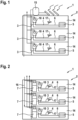
- Fig.1 shows the first design variant of a known heating system 1 in a property 2 with a plurality of residential units 14, here for example with three residential units 14.
- the heating water circulation system 5 and the supply system 3 for warm fresh water 4.
- the heat-transporting fluid 6 flowing through the heating water circulation system 5 is heated by heat generators 10. These are designed as pure heating devices for the fluid 6.
- the warm fresh water 4 is supplied via renewable energies.
- a solar system 15 is provided, which acts as a central system to supply several residential units 14.
- Fig. 2 shows a second embodiment of a known heating system 1 in a property 2 with a plurality of residential units 14, here for example with three residential units 14.
- the heat-transporting fluid 6 flowing through the heating water circulation system 5 is heated by heat generators 10. These are designed as pure heating devices for the fluid 6.
- the warm fresh water 4 is heated using renewable energies, with each residential unit 14 having a heat pump 7.
- the heat pumps 7 are supplied with warm air via a ventilation system 16.
- This ventilation system 16 supplies several residential units 14 as a central system.
- Fig.3 shows a first embodiment of a heating system 1.
- the heating system 1 has a supply system 3 for warm fresh water 4, a heating water circulation system 5 which comprises a fluid 6 as a heat carrier, a storage tank 8 with a volume 9 which can be tempered by a heat pump 7, and a heat generator 10.
- the fluid 6 and the fresh water 4 can be heated via the storage tank 8 and subsequently via the heat generator 10.
- the volume 9 of the storage tank 8 is filled with the fluid 6 of the heating water circulation system 5.
- the storage tank 8 has an inlet (bottom right on the storage tank 8) and an outlet (top right) for the fluid 6, whereby the fluid 6 within the storage tank 8 is heated by the operation of the heat pump 7.
- the fresh water 4 is also heated via the storage tank 8 or the heat pump 7.
- the fresh water 4 and the fluid 6 are fluidically separated from one another.
- the fresh water 4 is guided through a pipe 11, which extends at least partially in a spiral shape through the volume 9 of the storage tank 8.
- the fresh water 4 can thus be heated by the fluid 6 that flows around the pipe 11.
- the pipe 11 is connected to a public fresh water system and has an outlet 17 within the property 2. Both the The fresh water 4 already heated by the storage tank 8 as well as the fluid 6 can subsequently be further heated by the heat generator 10, i.e. downstream of the storage tank 8.
- the heat pump 7 has a first housing 12 and the heat generator 10 has a second housing 13.
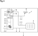
- Fig.4 shows a second variant of a heating system 1.
- the heat pump 7 and the heat generator 10 are designed as a single unit, i.e. they are arranged within a common first housing 12.
- the fresh water 4 can also be subsequently heated (electrically) via the heat generator 10.
- the volume 9 of the storage tank 8 is filled with the fluid 6 of the heating water circulation system 5.
- the storage tank 8 has an inlet (bottom right of the storage tank 8) and an outlet (top, towards the heat generator 10) for the fluid 6, with the fluid 6 within the storage tank 8 being heated by the operation of the heat pump 7.
- the fresh water 4 is also heated via the storage tank 8 or the heat pump 7.
- the fresh water 4 and the fluid 6 are fluidically separated from one another.
- the fresh water 4 is guided through a line 11 which extends at least partially in a spiral shape through the volume 9 of the storage tank 8.
- the fresh water 4 can thus be heated by the fluid 6 that flows around the line 11.
- the line 11 is connected to a public fresh water system and has an outlet 17 within the property 2. Fluid 6 can be further heated via the heat generator 10.
- Fig.5 shows a third embodiment of a heating system 1 in a property 2 with a plurality of residential units 14, here for example with three residential units 14.
- the heating system 1 of each residential unit 14 is as in Figure 3
- the heat-transporting fluid 6 flowing through the heating water circulation system 5 and the fresh water 4 are preheated or heated using renewable energies and, if necessary, further heated to a desired temperature using a heat generator 10.
- Each Residential unit 14 has a heat pump 7 and a heat generator 10.
- the heat pumps 7 are supplied with warm air via a ventilation system 16.
- This ventilation system 16 acts as a central system and supplies several residential units 14.
- Fig.6 shows a fourth embodiment of a heating system 1 in a property 2 with a plurality of residential units 14, here for example with three residential units 14.
- the heating system 1 of each residential unit 14 is similar to Figure 3 shown.
- the heat-transporting fluid 6 flowing through the heating water circulation system 5 and the fresh water 4 are preheated or heated using renewable energies and, if necessary, further heated to a desired temperature using a heat generator 10.
- Each residential unit 14 has a heat pump 7 and a heat generator 10.
- the heat pumps 7 are supplied with heated water from a solar system 15, which acts as a central system for supplying several residential units 14.
Landscapes
- Engineering & Computer Science (AREA)
- Physics & Mathematics (AREA)
- Thermal Sciences (AREA)
- Chemical & Material Sciences (AREA)
- Combustion & Propulsion (AREA)
- Mechanical Engineering (AREA)
- General Engineering & Computer Science (AREA)
- Water Supply & Treatment (AREA)
- Central Heating Systems (AREA)
Applications Claiming Priority (1)
| Application Number | Priority Date | Filing Date | Title |
|---|---|---|---|
| DE102023107214.5A DE102023107214A1 (de) | 2023-03-22 | 2023-03-22 | Heizsystem für eine Immobilie und Verfahren zum Betrieb eines Heizsystems |
Publications (1)
| Publication Number | Publication Date |
|---|---|
| EP4435332A1 true EP4435332A1 (fr) | 2024-09-25 |
Family
ID=90366655
Family Applications (1)
| Application Number | Title | Priority Date | Filing Date |
|---|---|---|---|
| EP24164399.8A Pending EP4435332A1 (fr) | 2023-03-22 | 2024-03-19 | Système de chauffage pour un bien immobilier et procédé de fonctionnement d'un système de chauffage |
Country Status (2)
| Country | Link |
|---|---|
| EP (1) | EP4435332A1 (fr) |
| DE (1) | DE102023107214A1 (fr) |
Citations (7)
| Publication number | Priority date | Publication date | Assignee | Title |
|---|---|---|---|---|
| DE10244339A1 (de) | 2002-09-24 | 2004-04-01 | Robert Bosch Gmbh | Heizungsanlage für ein Gebäude |
| CH708784A2 (de) | 2013-10-22 | 2015-04-30 | Swissframe Vertriebs Ag | Warmwassersystem zur Bereitstellung von Trinkwasser. |
| CN106439984A (zh) * | 2016-10-24 | 2017-02-22 | 中国市政工程华北设计研究总院有限公司 | 应用于独立供热采暖系统的多能互补供热系统 |
| EP2762789B1 (fr) * | 2013-02-05 | 2019-01-16 | Riello S.p.A. | Installation avec multiples sources de chaleur intégrées |
| EP3617601A1 (fr) | 2018-08-29 | 2020-03-04 | Stiebel Eltron GmbH & Co. KG | Système d'eau chaude, en particulier installation de chauffage d'eau potable et de conduites d'eau potable |
| EP3385624B1 (fr) * | 2017-04-07 | 2020-09-30 | MHG Heiztechnik GmbH | Procédé de fonctionnement d'une installation de préparation d'eau sanitaire ou de chauffage, et installation de préparation d'eau sanitaire |
| DE102020127443A1 (de) | 2020-10-19 | 2022-04-21 | Solvis GmbH | Klimatisierungsanlage für ein Gebäude |
Family Cites Families (1)
| Publication number | Priority date | Publication date | Assignee | Title |
|---|---|---|---|---|
| NL2011960C2 (nl) * | 2013-12-13 | 2015-06-16 | Intergas Heating Assets B V | Warmtewisselaar, verwarmingsinrichting, verwarmingssysteem en werkwijze voor de toepassing daarvan. |
-
2023
- 2023-03-22 DE DE102023107214.5A patent/DE102023107214A1/de active Pending
-
2024
- 2024-03-19 EP EP24164399.8A patent/EP4435332A1/fr active Pending
Patent Citations (8)
| Publication number | Priority date | Publication date | Assignee | Title |
|---|---|---|---|---|
| DE10244339A1 (de) | 2002-09-24 | 2004-04-01 | Robert Bosch Gmbh | Heizungsanlage für ein Gebäude |
| EP2762789B1 (fr) * | 2013-02-05 | 2019-01-16 | Riello S.p.A. | Installation avec multiples sources de chaleur intégrées |
| CH708784A2 (de) | 2013-10-22 | 2015-04-30 | Swissframe Vertriebs Ag | Warmwassersystem zur Bereitstellung von Trinkwasser. |
| CH708784B1 (de) * | 2013-10-22 | 2017-12-15 | Swissframe Vertriebs Ag | Verfahren und Warmwassersystem zur Bereitstellung von erwärmtem Frischwasser. |
| CN106439984A (zh) * | 2016-10-24 | 2017-02-22 | 中国市政工程华北设计研究总院有限公司 | 应用于独立供热采暖系统的多能互补供热系统 |
| EP3385624B1 (fr) * | 2017-04-07 | 2020-09-30 | MHG Heiztechnik GmbH | Procédé de fonctionnement d'une installation de préparation d'eau sanitaire ou de chauffage, et installation de préparation d'eau sanitaire |
| EP3617601A1 (fr) | 2018-08-29 | 2020-03-04 | Stiebel Eltron GmbH & Co. KG | Système d'eau chaude, en particulier installation de chauffage d'eau potable et de conduites d'eau potable |
| DE102020127443A1 (de) | 2020-10-19 | 2022-04-21 | Solvis GmbH | Klimatisierungsanlage für ein Gebäude |
Also Published As
| Publication number | Publication date |
|---|---|
| DE102023107214A1 (de) | 2024-09-26 |
Similar Documents
| Publication | Publication Date | Title |
|---|---|---|
| DE102007009196B4 (de) | Auf Basis erneuerbarer Energieträger arbeitendes Warmwasser- und Heizungssystem | |
| EP0085774B1 (fr) | Procédé pour préparer de l'eau chaude sanitaire en économisant l'énergie dans des bâtiments d'habitation, en particulier dans des bâtiments de grande et moyenne importances et dispositif pour sa mise en oeuvre | |
| DE102019000430B4 (de) | Verfahren zur Erreichung sehr niedriger Rücklauftemperaturen mittels einer Wärmepumpe, Heizanordnung zur Durchführung des Verfahrens, sowie System für Wärme- und Kälteverteilnetze | |
| DE4434831A1 (de) | Anlage zur kombinierten Energieerzeugung | |
| EP3835666B1 (fr) | Système de bâtiment destiné à la climatisation et à l'approvisionnement en chaleur | |
| EP3006682A1 (fr) | Dispositif et procédé de fonctionnement d'une station de transmission thermique | |
| EP2354677A1 (fr) | Système à triple ou quadruple conducteur destiné à l'économie d'énergie pour chauffages urbains | |
| DE212018000133U1 (de) | Kombiniertes System aus einer Brauchwassererwärmung und einem Heizmedium zur Wohnungsheizung | |
| DE102023100930A1 (de) | Wärmepumpensystem und Quartier | |
| EP2795199B1 (fr) | Système et procédé d'alimentation thermique | |
| DE69510944T2 (de) | Verfahren und einrichtung von heiz-und/oder kühlenergie | |
| EP2458304A2 (fr) | Installation de pompe à chaleur comprenant une pompe à chaleur et procédé de fonctionnement d'une telle installation de pompe à chaleur | |
| DE102008033063B4 (de) | Verfahren und Vorrichtung zur zentralen Warmwasserversorgung | |
| EP0647818B1 (fr) | Système de chauffage décentralisé dans lequel usage est fait de techniques de conduites d'écoulement multiples | |
| EP4435332A1 (fr) | Système de chauffage pour un bien immobilier et procédé de fonctionnement d'un système de chauffage | |
| EP2492599A2 (fr) | Installation de chauffage dotée d'une combustion de biomasse et d'une pompe à chaleur | |
| EP2116797A2 (fr) | Pompe à chaleur | |
| DE2730406A1 (de) | Vorrichtungen und verfahren zur erhoehung der transportleistung von fernwaermenetzen | |
| DE102024114023A1 (de) | System zur Temperierung eines Gebäudes | |
| EP2815196B1 (fr) | Échangeur de chaleur pour une installation de chauffage ou un système de fourniture de chaleur | |
| DE202023001213U1 (de) | Modulare geothermische Energieanlage | |
| DE102022132759A1 (de) | System zur Wärme- und Kälteversorgung mehrerer Verbraucher | |
| DE102015115056B4 (de) | System zum Beheizen eines Gebäudes | |
| DE3019475A1 (de) | System zur waermegewinnung aus solar- bzw. umgebungsenergie | |
| DE102024132017A1 (de) | Wärmepumpe zur Versorgung eines Gebäudes mit Wärme und Warmwasser, Verfahren zum Betreiben einer Wärmepumpe und Computerprogrammprodukt |
Legal Events
| Date | Code | Title | Description |
|---|---|---|---|
| PUAI | Public reference made under article 153(3) epc to a published international application that has entered the european phase |
Free format text: ORIGINAL CODE: 0009012 |
|
| STAA | Information on the status of an ep patent application or granted ep patent |
Free format text: STATUS: THE APPLICATION HAS BEEN PUBLISHED |
|
| AK | Designated contracting states |
Kind code of ref document: A1 Designated state(s): AL AT BE BG CH CY CZ DE DK EE ES FI FR GB GR HR HU IE IS IT LI LT LU LV MC ME MK MT NL NO PL PT RO RS SE SI SK SM TR |
|
| STAA | Information on the status of an ep patent application or granted ep patent |
Free format text: STATUS: REQUEST FOR EXAMINATION WAS MADE |
|
| 17P | Request for examination filed |
Effective date: 20250319 |