EP4435565A1 - Elektronische vorrichtung und steuerungsverfahren dafür - Google Patents
Elektronische vorrichtung und steuerungsverfahren dafür Download PDFInfo
- Publication number
- EP4435565A1 EP4435565A1 EP23784878.3A EP23784878A EP4435565A1 EP 4435565 A1 EP4435565 A1 EP 4435565A1 EP 23784878 A EP23784878 A EP 23784878A EP 4435565 A1 EP4435565 A1 EP 4435565A1
- Authority
- EP
- European Patent Office
- Prior art keywords
- user
- identified
- preset zone
- screen
- preset
- Prior art date
- Legal status (The legal status is an assumption and is not a legal conclusion. Google has not performed a legal analysis and makes no representation as to the accuracy of the status listed.)
- Pending
Links
Images













Classifications
-
- G—PHYSICS
- G06—COMPUTING OR CALCULATING; COUNTING
- G06F—ELECTRIC DIGITAL DATA PROCESSING
- G06F3/00—Input arrangements for transferring data to be processed into a form capable of being handled by the computer; Output arrangements for transferring data from processing unit to output unit, e.g. interface arrangements
- G06F3/01—Input arrangements or combined input and output arrangements for interaction between user and computer
- G06F3/048—Interaction techniques based on graphical user interfaces [GUI]
- G06F3/0484—Interaction techniques based on graphical user interfaces [GUI] for the control of specific functions or operations, e.g. selecting or manipulating an object, an image or a displayed text element, setting a parameter value or selecting a range
- G06F3/04842—Selection of displayed objects or displayed text elements
-
- G—PHYSICS
- G06—COMPUTING OR CALCULATING; COUNTING
- G06V—IMAGE OR VIDEO RECOGNITION OR UNDERSTANDING
- G06V40/00—Recognition of biometric, human-related or animal-related patterns in image or video data
- G06V40/10—Human or animal bodies, e.g. vehicle occupants or pedestrians; Body parts, e.g. hands
- G06V40/16—Human faces, e.g. facial parts, sketches or expressions
-
- G—PHYSICS
- G02—OPTICS
- G02F—OPTICAL DEVICES OR ARRANGEMENTS FOR THE CONTROL OF LIGHT BY MODIFICATION OF THE OPTICAL PROPERTIES OF THE MEDIA OF THE ELEMENTS INVOLVED THEREIN; NON-LINEAR OPTICS; FREQUENCY-CHANGING OF LIGHT; OPTICAL LOGIC ELEMENTS; OPTICAL ANALOGUE/DIGITAL CONVERTERS
- G02F1/00—Devices or arrangements for the control of the intensity, colour, phase, polarisation or direction of light arriving from an independent light source, e.g. switching, gating or modulating; Non-linear optics
- G02F1/01—Devices or arrangements for the control of the intensity, colour, phase, polarisation or direction of light arriving from an independent light source, e.g. switching, gating or modulating; Non-linear optics for the control of the intensity, phase, polarisation or colour
- G02F1/13—Devices or arrangements for the control of the intensity, colour, phase, polarisation or direction of light arriving from an independent light source, e.g. switching, gating or modulating; Non-linear optics for the control of the intensity, phase, polarisation or colour based on liquid crystals, e.g. single liquid crystal display cells
- G02F1/133—Constructional arrangements; Operation of liquid crystal cells; Circuit arrangements
- G02F1/1333—Constructional arrangements; Manufacturing methods
-
- G—PHYSICS
- G06—COMPUTING OR CALCULATING; COUNTING
- G06F—ELECTRIC DIGITAL DATA PROCESSING
- G06F1/00—Details not covered by groups G06F3/00 - G06F13/00 and G06F21/00
- G06F1/16—Constructional details or arrangements
- G06F1/1613—Constructional details or arrangements for portable computers
- G06F1/1633—Constructional details or arrangements of portable computers not specific to the type of enclosures covered by groups G06F1/1615 - G06F1/1626
- G06F1/1684—Constructional details or arrangements related to integrated I/O peripherals not covered by groups G06F1/1635 - G06F1/1675
- G06F1/1694—Constructional details or arrangements related to integrated I/O peripherals not covered by groups G06F1/1635 - G06F1/1675 the I/O peripheral being a single or a set of motion sensors for pointer control or gesture input obtained by sensing movements of the portable computer
-
- G—PHYSICS
- G06—COMPUTING OR CALCULATING; COUNTING
- G06F—ELECTRIC DIGITAL DATA PROCESSING
- G06F3/00—Input arrangements for transferring data to be processed into a form capable of being handled by the computer; Output arrangements for transferring data from processing unit to output unit, e.g. interface arrangements
-
- G—PHYSICS
- G06—COMPUTING OR CALCULATING; COUNTING
- G06F—ELECTRIC DIGITAL DATA PROCESSING
- G06F3/00—Input arrangements for transferring data to be processed into a form capable of being handled by the computer; Output arrangements for transferring data from processing unit to output unit, e.g. interface arrangements
- G06F3/01—Input arrangements or combined input and output arrangements for interaction between user and computer
-
- G—PHYSICS
- G06—COMPUTING OR CALCULATING; COUNTING
- G06F—ELECTRIC DIGITAL DATA PROCESSING
- G06F3/00—Input arrangements for transferring data to be processed into a form capable of being handled by the computer; Output arrangements for transferring data from processing unit to output unit, e.g. interface arrangements
- G06F3/01—Input arrangements or combined input and output arrangements for interaction between user and computer
- G06F3/017—Gesture based interaction, e.g. based on a set of recognized hand gestures
-
- G—PHYSICS
- G06—COMPUTING OR CALCULATING; COUNTING
- G06F—ELECTRIC DIGITAL DATA PROCESSING
- G06F3/00—Input arrangements for transferring data to be processed into a form capable of being handled by the computer; Output arrangements for transferring data from processing unit to output unit, e.g. interface arrangements
- G06F3/14—Digital output to display device ; Cooperation and interconnection of the display device with other functional units
-
- G—PHYSICS
- G06—COMPUTING OR CALCULATING; COUNTING
- G06V—IMAGE OR VIDEO RECOGNITION OR UNDERSTANDING
- G06V10/00—Arrangements for image or video recognition or understanding
- G06V10/20—Image preprocessing
- G06V10/25—Determination of region of interest [ROI] or a volume of interest [VOI]
-
- G—PHYSICS
- G06—COMPUTING OR CALCULATING; COUNTING
- G06V—IMAGE OR VIDEO RECOGNITION OR UNDERSTANDING
- G06V40/00—Recognition of biometric, human-related or animal-related patterns in image or video data
- G06V40/10—Human or animal bodies, e.g. vehicle occupants or pedestrians; Body parts, e.g. hands
- G06V40/16—Human faces, e.g. facial parts, sketches or expressions
- G06V40/172—Classification, e.g. identification
-
- H—ELECTRICITY
- H04—ELECTRIC COMMUNICATION TECHNIQUE
- H04B—TRANSMISSION
- H04B17/00—Monitoring; Testing
- H04B17/30—Monitoring; Testing of propagation channels
- H04B17/309—Measuring or estimating channel quality parameters
- H04B17/318—Received signal strength
-
- H—ELECTRICITY
- H04—ELECTRIC COMMUNICATION TECHNIQUE
- H04M—TELEPHONIC COMMUNICATION
- H04M1/00—Substation equipment, e.g. for use by subscribers
- H04M1/72—Mobile telephones; Cordless telephones, i.e. devices for establishing wireless links to base stations without route selection
- H04M1/724—User interfaces specially adapted for cordless or mobile telephones
- H04M1/72403—User interfaces specially adapted for cordless or mobile telephones with means for local support of applications that increase the functionality
- H04M1/72409—User interfaces specially adapted for cordless or mobile telephones with means for local support of applications that increase the functionality by interfacing with external accessories
- H04M1/72415—User interfaces specially adapted for cordless or mobile telephones with means for local support of applications that increase the functionality by interfacing with external accessories for remote control of appliances
-
- H—ELECTRICITY
- H04—ELECTRIC COMMUNICATION TECHNIQUE
- H04N—PICTORIAL COMMUNICATION, e.g. TELEVISION
- H04N21/00—Selective content distribution, e.g. interactive television or video on demand [VOD]
- H04N21/40—Client devices specifically adapted for the reception of or interaction with content, e.g. set-top-box [STB]; Operations thereof
- H04N21/41—Structure of client; Structure of client peripherals
- H04N21/422—Input-only peripherals, i.e. input devices connected to specially adapted client devices, e.g. global positioning system [GPS]
- H04N21/4223—Cameras
-
- H—ELECTRICITY
- H04—ELECTRIC COMMUNICATION TECHNIQUE
- H04N—PICTORIAL COMMUNICATION, e.g. TELEVISION
- H04N21/00—Selective content distribution, e.g. interactive television or video on demand [VOD]
- H04N21/40—Client devices specifically adapted for the reception of or interaction with content, e.g. set-top-box [STB]; Operations thereof
- H04N21/43—Processing of content or additional data, e.g. demultiplexing additional data from a digital video stream; Elementary client operations, e.g. monitoring of home network or synchronising decoder's clock; Client middleware
- H04N21/442—Monitoring of processes or resources, e.g. detecting the failure of a recording device, monitoring the downstream bandwidth, the number of times a movie has been viewed, the storage space available from the internal hard disk
- H04N21/44213—Monitoring of end-user related data
- H04N21/44218—Detecting physical presence or behaviour of the user, e.g. using sensors to detect if the user is leaving the room or changes his face expression during a TV programme
-
- H—ELECTRICITY
- H10—SEMICONDUCTOR DEVICES; ELECTRIC SOLID-STATE DEVICES NOT OTHERWISE PROVIDED FOR
- H10K—ORGANIC ELECTRIC SOLID-STATE DEVICES
- H10K59/00—Integrated devices, or assemblies of multiple devices, comprising at least one organic light-emitting element covered by group H10K50/00
- H10K59/40—OLEDs integrated with touch screens
-
- G—PHYSICS
- G06—COMPUTING OR CALCULATING; COUNTING
- G06F—ELECTRIC DIGITAL DATA PROCESSING
- G06F2200/00—Indexing scheme relating to G06F1/04 - G06F1/32
- G06F2200/16—Indexing scheme relating to G06F1/16 - G06F1/18
- G06F2200/163—Indexing scheme relating to constructional details of the computer
- G06F2200/1636—Sensing arrangement for detection of a tap gesture on the housing
-
- G—PHYSICS
- G06—COMPUTING OR CALCULATING; COUNTING
- G06V—IMAGE OR VIDEO RECOGNITION OR UNDERSTANDING
- G06V2201/00—Indexing scheme relating to image or video recognition or understanding
- G06V2201/07—Target detection
-
- H—ELECTRICITY
- H04—ELECTRIC COMMUNICATION TECHNIQUE
- H04M—TELEPHONIC COMMUNICATION
- H04M1/00—Substation equipment, e.g. for use by subscribers
- H04M1/72—Mobile telephones; Cordless telephones, i.e. devices for establishing wireless links to base stations without route selection
- H04M1/724—User interfaces specially adapted for cordless or mobile telephones
- H04M1/72403—User interfaces specially adapted for cordless or mobile telephones with means for local support of applications that increase the functionality
- H04M1/72409—User interfaces specially adapted for cordless or mobile telephones with means for local support of applications that increase the functionality by interfacing with external accessories
- H04M1/72412—User interfaces specially adapted for cordless or mobile telephones with means for local support of applications that increase the functionality by interfacing with external accessories using two-way short-range wireless interfaces
Definitions
- This disclosure relates to an electronic apparatus and a control method thereof and, more particularly to, an electronic apparatus communicating with an external device and a control method thereof.
- a function provided by an electronic apparatus such as a TV is diversified according to the development of technology.
- an electronic apparatus providing an image through a display such as a TV a function of manipulating an electronic apparatus of a TV by sharing (or mirroring) through connection to an external device, or using a mobile such as a smartphone has been widely used.
- a user input In order to connect an electronic apparatus and an external device, a user input must be received through a user interface (UI) provided through an electronic apparatus or an external device, and in the case of the UI, a large number of depths are required so that a user has inconvenience to execute a function.
- UI user interface
- a problem of misrecognition and malfunction has frequently occurred since an electronic apparatus and an external device are connected in a time or area different from the user's intention.
- An electronic apparatus includes a display; a camera; a communication interface; a memory storing information related to a specific object; and one or more processor configured to, based on the specific object being identified from an image obtained through the camera, identify a preset zone with respect to the identified specific object, based on a user being identified from the image obtained through the camera, identify whether the identified user is located within the preset zone, and based on a signal corresponding to a user interaction input to the terminal being received by the communication interface while the user is located in the preset zone, control the display to display a UI screen corresponding to a type of the user interaction.
- the one or more processor may control the display to display an image including the specific object, control the display to display a UI screen to set a preset zone on the displayed image, and identify the preset zone based on a user command input through the displayed UI screen.
- the one or more processor may, based on identifying that the identified user is located in the preset zone for a threshold time or longer, identify that the user is located in the preset zone.
- the one or more processor may control the display to display an image including a plurality of specific objects, control the display to display a UI screen to set a preset zone corresponding to each of the plurality of specific objects from the displayed image, and identify preset zones corresponding to each of the plurality of specific objects based on a user command input through the displayed UI screen.
- the one or more processor may control the display to display a UI screen representing an identified region based on each of the plurality of specific objects, and identify at least one region selected based on a user command, among regions identified based on each of the plurality of specific objects, as the preset zone.
- the one or more processor may store information about a plurality of preset zones mapped to face information of a plurality of users in the memory, based on face information of a first user being identified from an image obtained through the camera, obtain information about a plurality of preset zones mapped to face information of the first user among face information of the plurality of users, and identify whether the first user is located within the plurality of preset zones.
- the one or more processor may identify a control command corresponding to a type of the user interaction, based on the identified control command being a command to control a UI screen provided by the user terminal, transmit, to the user terminal through the communication interface, a control signal to provide a UI screen corresponding to content displayed on the display in the user terminal.
- the one or more processor may identify whether the user terminal is located within the preset zone based on received signal strength indication (RSSI) size information of a signal periodically received from the user terminal, and based on identifying that the user terminal is located within the preset zone, identify that the user is located within the preset zone.
- RSSI received signal strength indication
- the one or more processor may, based on the specific object being identified from a first image obtained through the camera, identify a preset zone with respect to the identified specific object, and store information on the identified preset zone in the memory, and based on the user being identified from a second image obtained through the camera, identify whether the identified user is located within the preset zone based on information about the preset zone stored in the memory.
- the UI screen corresponding to a type of the user interaction may be a UI screen for providing multi device experience (MDE).
- MDE multi device experience
- a control method of an electronic apparatus includes, based on a specific object being identified from an image obtained through a camera, identifying a preset zone with respect to the identified specific object; based on a user being identified from the image obtained through the camera, identifying whether the identified user is located within the preset zone; and based on a signal corresponding to a user interaction input to the terminal being received by the communication interface while the user is located in the preset zone, displaying a user interface (UI) screen corresponding to a type of the user interaction.
- UI user interface
- the identifying the preset zone may include displaying an image including the specific object; displaying a UI screen to set a preset zone on the displayed image; and identifying the preset zone based on a user command input through the displayed UI screen.
- the identifying the preset zone may include, based on identifying that the identified user is located in the preset zone for a threshold time or longer, identifying that the user is located in the preset zone.
- the identifying the preset zone may include displaying an image including a plurality of specific objects; displaying a UI screen to set a preset zone corresponding to each of the plurality of specific objects from the displayed image; and identifying preset zones corresponding to each of the plurality of specific objects based on a user command input through the displayed UI screen.
- the displaying the UI screen may include displaying a UI screen representing an identified region based on each of the plurality of specific objects, and the identifying the preset zone corresponding to each of the plurality of specific objects may include identifying at least one region selected based on a user command, among regions identified based on each of the plurality of specific objects, as the preset zone.
- the method may further include storing information about a plurality of preset zones mapped to face information of a plurality of users in the memory, based on face information of a first user being identified from an image obtained through the camera, obtaining information about a plurality of preset zones mapped to face information of the first user among face information of the plurality of users, and identifying whether the first user is located within the plurality of preset zones.
- the method may further include identifying a control command corresponding to a type of the user interaction, based on the identified control command being a command to control a UI screen provided by the user terminal, transmitting, to the user terminal through the communication interface, a control signal to provide a UI screen corresponding to content displayed on the display in the user terminal.
- the identifying whether the identified user is located in the preset zone may include identifying whether the user terminal is located within the preset zone based on received signal strength indication (RSSI) size information of a signal periodically received from the user terminal, and based on identifying that the user terminal is located within the preset zone, identifying that the user is located within the preset zone.
- RSSI received signal strength indication
- the method may include, based on the specific object being identified from a first image obtained through the camera, identifying a preset zone with respect to the identified specific object, and store information on the identified preset zone in the memory, and based on the user being identified from a second image obtained through the camera, identifying whether the identified user is located within the preset zone based on information about the preset zone stored in the memory.
- the UI screen corresponding to a type of the user interaction may be a UI screen for providing multi device experience (MDE).
- MDE multi device experience
- first and “second,” may identify corresponding components, regardless of order and/or importance, and are used to distinguish a component from another without limiting the components.
- one element e.g., a first element
- another element e.g., a second element
- a description that one element should be interpreted to include both the first element being directly coupled to the second element, and the first element being indirectly coupled to the second element through an intervening third element.
- module A term such as “module,” “unit,” and “part,” is used to refer to an element that performs at least one function or operation and that may be implemented as hardware or software, or a combination of hardware and software. Except when each of a plurality of “modules,” “units,” “parts,” and the like must be realized in an individual hardware, the components may be integrated in at least one module or chip and be realized in at least one processor.
- FIG. 1 is a diagram illustrating an operation method of an electronic apparatus according to an embodiment of the disclosure.
- the electronic apparatus 100 includes a TV, a PC, a laptop computer, a smartphone, a tablet PC, a mobile medical device, a wearable device, an electronic blackboard (Interactive whiteboard), electronic picture frames, kiosks, virtual reality (VR) device, drone, and the like.
- the electronic apparatus 100 may be implemented in a form having a camera.
- the electronic apparatus 100 may perform a function corresponding to a user command received from the user terminal 200.
- the user terminal 200 may be implemented in various types of electronic apparatuses that receive user commands for controlling the electronic apparatus 100 such as a smartphone, a tablet PC, a mobile medical device, a wearable device, an interactive whiteboard, a kiosk, and a game console.
- a touch screen may be provided together with a touch panel to receive a user's touch input.
- the electronic apparatus 100 may perform a multi device experience (MDE) function based on a user command received from the user terminal 200.
- MDE refers to a series of processes that provide various experiences to a user by applying Internet of Things (IoT) or artificial intelligence (AI) services to a plurality of electronic apparatuses of various types.
- IoT Internet of Things
- AI artificial intelligence
- the electronic apparatus 100 may perform a function of mirroring an image displayed on the user terminal 200 to the electronic apparatus 100. For example, when the electronic apparatus 100 receives a user command for performing a mirroring function from the user terminal 200, the electronic apparatus 100 may provide an image 122 and an image received from the user terminal 200, that is, the UI screen 121 including all images displayed on the user terminal 200.
- FIG. 2 is a block diagram illustrating a configuration of an electronic apparatus according to an embodiment of the disclosure.
- the electronic apparatus 100 may include a display 110, a camera 120, a communication interface 130, a memory 140, and one or more processor 150.
- the display 110 may be implemented as a display including a self-emitting element or a display including a non-self-limiting element and a backlight.
- the display 110 may be implemented as a display of various types such as, for example, and without limitation, a liquid crystal display (LCD), organic light emitting diodes (OLED) display, light emitting diodes (LED), micro LED, mini LED, plasma display panel (PDP), quantum dot (QD) display, quantum dot light-emitting diodes (QLED), or the like.
- LCD liquid crystal display
- OLED organic light emitting diodes
- LED light emitting diodes
- micro LED micro LED
- mini LED micro LED
- PDP plasma display panel
- QD quantum dot
- QLED quantum dot light-emitting diodes
- a backlight unit a driving circuit which may be implemented as an a-si TFT, low temperature poly silicon (LTPS) TFT, organic TFT (OTFT), or the like, may be included as well.
- the display 140 may be implemented as a touch screen coupled to a touch sensor, a flexible display, a rollable display, a third-dimensional (3D) display, a display in which a plurality of display modules are physically connected, or the like.
- the display 110 may include a touch screen and may execute a program using fingers or a pen (e.g., a stylus pen).
- the camera 120 may obtain an image by capturing an area within a certain field of view (FoV).
- the camera 120 may include a lens that focuses visible light and other optical signals reflected by an object and received by the image sensor, and an image sensor capable of detecting visible light and other optical signals.
- the image sensor may include a 2D pixel array divided into a plurality of pixels.
- the communication interface 130 may perform communication with a network device (not shown) such as another user terminal.
- the communication interface 130 may include a wireless communication module, for example, a Wi-Fi module, a Bluetooth module, or the like, but is not limited thereto, and the communication interface 130 may perform communication according to various communication standards such as Zigbee, 3rd generation (3G), 3rd generation partnership project (3GPP), long term evolution (LTE), LTE advanced (LTE-A), 4th generation (4G), 5th generation (5G), infrared data association (IrDA) technology, or the like, in addition to the communication methods as described above.
- 3G 3rd generation
- 3GPP 3rd generation partnership project
- LTE long term evolution
- LTE-A LTE advanced
- 5G 5th generation
- IrDA infrared data association
- the memory 140 may store data necessary for various embodiments of the disclosure.
- the memory 140 may be implemented as at least one of a memory embedded within the electronic apparatus 100 or a memory detachable from the electronic apparatus 100 according to the usage of data storage.
- the data for driving the electronic apparatus 100 may be stored in the memory embedded within the electronic apparatus 100
- the data for upscaling of the electronic apparatus 100 may be stored in the memory detachable from the electronic apparatus 100.
- the memory 140 embedded in the electronic apparatus 100 may be implemented as at least one of a volatile memory such as a dynamic random access memory (DRAM), a static random access memory (SRAM), a synchronous dynamic random access memory (SDRAM), or a non-volatile memory, such as one time programmable ROM (OTPROM), programmable ROM (PROM), erasable and programmable ROM (EPROM), electrically erasable and programmable ROM (EEPROM), mask ROM, flash ROM, a flash memory, such as NAND flash or NOR flash), a hard disk drive (HDD) or a solid state drive (SSD).
- a volatile memory such as a dynamic random access memory (DRAM), a static random access memory (SRAM), a synchronous dynamic random access memory (SDRAM), or a non-volatile memory, such as one time programmable ROM (OTPROM), programmable ROM (PROM), erasable and programmable ROM (EPROM), electrically erasable
- the memory may be implemented as a memory card, such as a compact flash (CF), secure digital (SD), micro secure digital (micro-SD), mini secure digital (mini-SD), extreme digital (xD), or multi-media card (MMC), and an external memory, such as a universal serial bus (USB) memory connectable to the USB port.
- CF compact flash
- SD secure digital
- micro-SD micro secure digital
- mini-SD mini secure digital
- xD extreme digital
- MMC multi-media card
- USB universal serial bus
- the information related to a preset zone may be stored in the memory 140.
- information related to a specific object to identify the preset zone and information about a preset zone identified based on the specific object may be stored in the memory 140.
- information about at least one preset zone mapped to each of face information of a plurality of users may be stored in the memory 140.
- the one or more processor 150 controls overall operations of the electronic apparatus 100.
- the one or more processor 150 is electrically connected to the each configuration of the electronic apparatus 100 to control the overall operation of the electronic apparatus 100.
- the one or more processor 150 may perform the operation of the electronic apparatus 100 according to various embodiments of the disclosure by executing at least one instruction stored in the memory 140.
- the one or more processor 150 may be connected to the display 110, camera 120, communication interface 130, and memory 140 for controlling the electronic apparatus 100.
- the one or more processor 150 may be called various names such as a digital signal processor (DSP), a microprocessor, a central processing unit (CPU), a micro controller unit (MCU), a micro processing unit (MPU), a controller, an application processor (AP), but herein the term processor 150 will be used.
- DSP digital signal processor
- CPU central processing unit
- MCU micro controller unit
- MPU micro processing unit
- AP application processor
- the one or more processor 150 may be implemented in a system on chip (SoC) type or a large scale integration (LSI) type in which a processing algorithm is built therein or in a field programmable gate array (FPGA) type.
- SoC system on chip
- LSI large scale integration
- FPGA field programmable gate array
- the one or more processor 150 may include a volatile memory like SRAM.
- the one or more processor 150 for executing the AI model may be implemented through combination of software and a general-purpose processor such as a central processor (CPU), an application processor (AP), a digital signal processor (DSP), a dedicated processor, or the like, a graphics-only processor such as a graphics processor (GPU), a vision processing unit (VPU), an AI-only processor such as a neural network processor (NPU), or the like.
- the one or more processor 150 may control processing of the input data according to a predefined operating rule or AI model stored in the memory 140. If the one or more processor 150 is an exclusive processor (or AI-only processor), the one or more processor 150 may be designed with a hardware structure specialized for the processing of a particular AI model.
- hardware specific to the processing of a particular AI model may be designed into a hardware chip, such as an application specific integrated circuit (ASIC), a field programmable gate array (FPGA), or the like.
- ASIC application specific integrated circuit
- FPGA field programmable gate array
- the one or more processor 150 may be implemented to include a memory to implement the embodiment of the disclosure, or to include a memory processing function for using an external memory.
- the one or more processor 150 may identify a preset zone based on the identified specific object.
- the specific object may be, for example, a table, a sofa, a chair, or the like, but is not limited thereto, and the specific object may be implemented as an object in a space where the user watches TV, or the like.
- a preset zone refers to an area including a specific object identified in an image obtained through the camera 120.
- the one or more processor 150 may identify a pixel region corresponding to the sofa as a preset zone, or identify a region including a pixel region corresponding to the sofa or a margin pixel region other than the corresponding pixel region.
- a preset zone may be changed according to a user input, and a specific method for identifying a preset zone will be described in detail with reference to FIGS. 3a to 3d below.
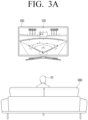
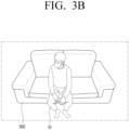
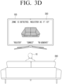
- FIGS. 3a to 3d are diagrams illustrating a preset zone according to an embodiment of the disclosure.
- the one or more processor 150 may obtain an image corresponding to a viewing space through the camera 120.
- Image information on the user 10, the object 300, and the surrounding environment of the user 10 may be included in an image corresponding to the viewing space, and an image corresponding to the viewing space may be obtained in real time.
- FIG. 3a when the user 10 sits on the sofa 300 positioned on the front surface of the electronic apparatus 100, a captured image as illustrated in FIG. 3b may be obtained.
- the one or more processor 150 may control the display 110 to display an image including a specific object as illustrated in FIG. 3c and display a UI screen 320 for setting a preset zone in the displayed image.
- the one or more processor 130 may analyze a pixel value included in the captured image to identify whether a specific object is included in the captured image.
- the one or more processor 150 may input a captured image to a trained neural network model to identify whether a specific object is included in the captured image. For example, in order to identify a specific object, a deep learning method such as object labelling may be used.
- the object labelling refers to receiving image information, classifying and localizing an object or region included in the image information, and labelling the object or region.
- a neural network model may be trained by labelling each of a learning image including a sofa and a learning image that does not include a sofa.
- the one or more processor 150 may control the display 110 to display an image including the sofa 300, which is a specific object, and a UI screen 320 for setting a preset zone.
- the one or more processor 150 may display a pixel region 321 corresponding to the sofa 300 in an image separately from the other region.
- the one or more processor 150 may identify a preset zone based on a user command input through the displayed UI 320. According to an embodiment, it is assumed that the region 321 corresponding to the sofa 300 in an image is identified.
- the one or more processor 150 may identify an area corresponding to the user command as a preset zone. For example, when a user command for changing a horizontal size of a pixel region 321 corresponding to a sofa is input, the one or more processor 150 may identify a pixel region corresponding to the size changed in the left and right direction as a preset zone.
- the one or more processor 150 may control the display 110 to display a UI 330 for storing (or “registering”), changing (or “modifying"), or re-identifying (or “re-generating”) information about the identified preset zone as shown in FIG. 3d .
- the information on the preset zone may be information on a pixel area of a preset zone in an image obtained through the camera 120.
- a preset zone may be identified based on received signal strength indication (RSSI) size information of the user terminal 200, which will be described in detail with reference to FIGS. 7 and 8 .
- RSSI received signal strength indication
- the one or more processor 150 may store information on the identified preset zone in the memory 140.
- the one or more processor 150 may control the display 110 to display the UI screen shown in FIG. 3c again.
- the one or more processor 150 may re-obtain an image corresponding to the viewing space through the camera 120 to identify a specific object in the image.
- the one or more processor 150 may identify whether the identified user is located within a preset zone. According to an embodiment, the one or more processor 150 may identify whether the user is located within a preset zone based on information on a preset zone pre-stored in the memory 140 and information on the location of the user. This will be described in detail with reference to FIGS. 6a and 6b .
- the one or more processor 150 may control the display 110 to display a UI screen corresponding to the type of the user interaction.
- the type, model, and function of the user terminal 200 as well as the type of the user interaction may be considered, but for convenience of description, the type of the user terminal 200 is assumed to be fixed.
- the user interaction type may include, for example, at least one of an interaction of tapping on the user terminal 200 or a shake interaction of shaking the user terminal 200.
- the embodiment is not limited thereto, and various user interactions may be included therein according to the type of the user terminal 200 such as flick, rolling, folding, and the like.
- the signal corresponding to the user interaction may be a signal for identifying the type of the user interaction by the electronic apparatus 100, but is not limited thereto, and may be a control command corresponding to the type of the user interaction.
- the one or more processor 150 may identify a corresponding control command based on the user interaction type.
- the UI screen corresponding to the type of the user interaction may be a UI screen providing multi device experience (MDE).
- MDE refers to a series of processes of providing various experiences to a user by applying IoT or AI services to a plurality of electronic apparatuses of various types. This will be described in detail with reference to FIG. 9 .
- the one or more processor 150 may identify a control command corresponding to the type of the user interaction. For example, when the identified control command is a command for controlling a UI screen provided by the user terminal 200, the one or more processor 150 may transmit a control signal for providing a corresponding UI screen of the context information of the electronic apparatus 100 to the user terminal 200 through the communication interface 130.
- the context information of the electronic apparatus 100 is information on content displayed in the electronic apparatus 100, and may include, for example, a type of content, a content provider, whether to provide a subtitle of content, and the like.
- the one or more processor 150 may transmit, to the user terminal 200 through the communication interface 130, a control signal for providing, by the user terminal 200, a UI screen corresponding to content (for example, the type of content) displayed on the display 110.
- a signal corresponding to a shake interaction is received from the user terminal 200 through the communication interface 130 while an image is displayed through the display 110.
- a control command corresponding to the shake interaction is a command for controlling a UI screen provided by the user terminal 200 instead of the electronic apparatus 100
- the one or more processor 150 may transmit the control signal described above to the user terminal 200 through the communication interface 130 so that a UI screen corresponding to the content displayed on the display 110 is provided by the user terminal 200. This will be described in detail with reference to FIGS. 10A to 10B .
- the one or more processor 150 may, if a plurality of specific objects are identified in the obtained image through a camera, identify a preset zone with respect to the plurality of identified specific objects.
- identify a preset zone with respect to the plurality of identified specific objects.
- the one or more processor 150 may identify whether the user terminal 200 is located within the preset zone based on received signal strength indication (RSSI) size information of a signal periodically received from the user terminal 200.
- RSSI size information when a Bluetooth low energy (BLE) broadcasting signal periodically emitted from the electronic apparatus 100 is transmitted to the user terminal 200, the user terminal 200 identifies the size of the transmitted BLE broadcasting signal, and the electronic apparatus 100 receives signal size information corresponding thereto from the user terminal 200.
- BLE Bluetooth low energy
- the one or more processor 150 may store received signal strength indication (RSSI) size information (or standard size information, threshold size information) to identify a preset zone in the memory 140 based on a signal received from the user terminal 200.
- RSSI received signal strength indication
- the one or more processor 150 may identify received signal strength indication (RSSI) size information of a signal periodically received from the user terminal 200, and when it is identified that the identified size information is less than or equal to the reference size, identify that the user terminal 200 is located within a preset zone. According to another example, when it is identified that the identified size information is greater than a reference size, it may be identified that the user terminal 200 is located outside a preset zone. When it is identified that the user terminal 200 is located within a preset zone, the one or more processor 150 may identify that the user 10 is located within a preset zone. This will be described in detail with reference to FIGS. 7 to 8 .
- RSSI received signal strength indication
- the one or more processor 150 may not only identify whether the user is located within a preset zone based on the image obtained through the camera 120, but also may identify whether the user is located within a preset zone based on RSSI size information received from the user terminal 200 as described above. For example, when the function of the camera 120 is turned off by the user, the one or more processor 150 may identify whether the user is located within a preset zone based on the RSSI size information.
- the one or more processor 150 may identify whether the user is located within a preset zone by using the RSSI size information together with the image obtained through the camera 120. For example, even when it is identified that the user is located within a preset zone based on an image obtained through the camera 120, if it is identified that the user is not located within the preset zone based on the received RSSI size information, it may be identified that the user is not located within the preset zone.
- the one or more processor 150 may, if it is identified that the user is not located within the preset zone based on the image obtained through the camera 120, identify that the user is not located within the preset zone based on the image obtained through the camera 120.
- FIGS. 4a to 4c are diagrams illustrating at least one preset zone according to an embodiment of the disclosure.
- the one or more processor 150 may display an image including a plurality of specific objects 411 to 414, and control the display 110 to display a UI 410 for setting a preset zone corresponding to each of a plurality of specific objects 411 to 414 in the displayed image.
- a deep learning method such as object labelling may be used to identify a specific object in the obtained image.
- the one or more processor 150 may identify a preset zone corresponding to each of the plurality of specific objects 411 to 414 based on the user command input through the displayed UI screen 420. For example, when four pixel regions corresponding to each of a plurality of specific objects 411 to 414 are identified, the one or more processor 150 may identify four pixel regions as a preset zone. The one or more processor 150 may identify all areas where the user is likely to be located as a preset zone. According to an embodiment, according to FIG. 4b , the one or more processor 150 may identify, as a preset zone, at least one area selected based on a user command from among areas identified based on each of the plurality of specific objects 411 to 414.
- the one or more processor 150 may identify a pixel region corresponding to the rightmost chair 414 among the pixel regions corresponding to the identified plurality of specific objects 411 to 414 as a preset zone.
- the one or more processor 150 may identify a pixel area corresponding to the user command as a preset zone.
- the one or more processor 150 may map identification information corresponding to a plurality of pixel regions and control the display 110 to provide a UI screen corresponding thereto. For example, when a plurality of specific objects 411 to 414 are identified, the one or more processor 150 may map four pixel areas corresponding to each of a plurality of specific objects 411 to 414 from the right to "Tap zone 1", “Tap zone 2", “Tap zone 3" and "Tap zone 4", respectively, to provide a UI screen corresponding thereto. Accordingly, a user may conveniently select a pixel region.
- the one or more processor 150 may control the display 110 to display a UI screen 430 for storing (or “registering”), changing (or “modifying”), or re-identifying (or “re-generating”) information about the identified preset zone.
- the one or more processor 150 may identify a type of a plurality of preset zones based on a user input, and identify a control command to provide different functions according to each of the plurality of zones based on a type of a preset zone and a user input.
- the one or more processor 150 may identify each of a plurality of preset zones as a main zone or a sub zone based on the user input.
- the main zone is a zone corresponding to a space where a user is mainly located
- the sub zone refers to a zone other than the main zone.
- the one or more processor 150 may receive a user input for identifying a function according to a user interaction of each sub zone network. For example, the one or more processor 150 may receive a user input for providing a UI screen for executing a specific application in the case of sub zone 1, and providing a UI screen for executing an accessibility function (for example, a function activation function for turning on a caption) in case of sub zone 2.
- an accessibility function for example, a function activation function for turning on a caption
- the one or more processor 150 may perform a corresponding function based on a user input for identifying a function according to the identified type of the zone (main zone or sub zone) and user interaction of each sub zone. For example, as shown in FIG. 4c , it is assumed that a plurality of tap zones are identified. In this case, the one or more processor 150 may identify an operation corresponding to the interaction type for each of the plurality of preset zones based on the user input. When it is identified that the user is located within the tap zone 1 (414) identified as the main zone, the one or more processor 150 may control the display 110 to provide a UI screen for mirroring the user terminal 200 when the tap interaction is received.
- the one or more processor 150 may control the display 110 to provide a UI screen for executing a specific application when the tap interaction is received.
- the display 110 may be controlled to provide a UI screen for executing an accessibility function (for example, a function to activate turning on a caption).
- the one or more processor 150 may provide a user with a UI screen for performing different functions for each of the plurality of preset zones when the same user interactions are received.
- the one or more processor 150 may identify a preset zone based on face information of a plurality of users, and may identify whether the user is located within a preset zone based on the identified zone.
- the face information of the user is information on the distance between the facial features of the user and the geometric structure of the face, and when a user is included in the image obtained through the camera 120, the one or more processor 150 may obtain face information of the user through an artificial intelligence (AI) module using the information as input information.
- AI artificial intelligence
- the one or more processor 150 may store information about a plurality of preset zones mapped to face information of a plurality of users in the memory 140. For example, based on face information of a first user being identified from an image obtained through the camera 120, information about a plurality of preset zones mapped to face information of the first user may be obtained among face information of the plurality of users, and whether the first user is located within the plurality of preset zones may be identified. When it is identified that there is no information on the mapped preset zone, the one or more processor 150 may identify a preset zone of the first user through the process of FIGS. 4a to 4c , map information on the identified zone to the face information of the first user, and store the mapped information in the memory 140.
- the one or more processor 150 may obtain information on a plurality of preset zones mapped to the face information of the first user through the memory 140, and may identify whether the first user is located within a plurality of preset zones based on the information.
- FIG. 5a is a diagram illustrating a method of identifying presence of a user according to an embodiment of the disclosure.
- the one or more processor 150 may identify whether a specific object and a user are present based on an image obtained through the camera 120. According to an embodiment, the one or more processor 150 may obtain a pixel region 511 corresponding to a specific object and a skeleton 512 corresponding to the user 10 through an image obtained through the camera 120. The one or more processor 150 may identify the presence of the user by identifying the body position of the user 10 based on the skeleton 512.
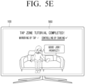
- FIGS. 5b to 5e are diagrams illustrating a method of providing a user interface (UI) screen according to an embodiment of the disclosure.
- the one or more processor 150 may control the display 110 to provide UI screens 530 to 560 for providing an experiential tutorial to the user 10 when a signal corresponding to the user interaction is first received or a user input corresponding to execution of the experiential tutorial function is received after the information on the preset zone is stored.
- the one or more processor 150 may control the display 110 to provide a UI screen 530 for guiding the user 10 to execute a tap input according to an example.
- the one or more processor 150 may control the display 110 to provide a UI screen 540 for guiding the user 10 to execute a shake input.
- the one or more processor 150 may control the display 110 to provide a UI screen 550 corresponding to a mirroring corresponding to a tap input as a signal corresponding to the tap input is received from the user terminal 200.
- the one or more processor 150 may transmit a control signal for executing a control command corresponding to the shake input to the user terminal 200 through the communication interface 130, and control the display 110 to provide a UI screen (560) showing that the tutorial has been completed.
- FIGS. 6a to 6b are diagrams illustrating a method of identifying whether a user is located within a preset zone according to an embodiment of the disclosure.
- the one or more processor 150 may obtain a skeleton corresponding to the user 10 through the obtained image. This has been described through FIG. 5a and a detailed description will be omitted.
- the one or more processor 150 may identify whether the identified user is located within a preset zone on the basis of information on a preset zone and skeleton corresponding to the user. As shown in FIG. 6a , when it is identified that a skeleton 612 corresponding to a user 10 identified in a pixel region 611 corresponding to a predetermined component is included, the one or more processor 150 may identify that the identified user 10 is located within a preset zone 611.
- a preset ratio is 80%.
- the one or more processor 150 may identify that the identified user 10 is located in the preset zone.
- the embodiment is not limited thereto, and the size of a preset ratio may be different.
- the one or more processor 150 may identify that the identified user 10 is not located in the preset zone if the ratio including the skeleton corresponding to the identified user 10 in the pixel area corresponding to the preset zone is less than a predetermined ratio. As shown in FIG. 6b , when the skeleton 613 corresponding to the user 10 is outside the preset zone 611 according to an embodiment, the one or more processor 150 may identify that the user 10 is outside the zone by identifying that the ratio including the skeleton corresponding to the user 10 in the preset zone 611 is 0%.
- the one or more processor 150 may not execute an operation corresponding thereto, and may reduce misrecognition and malfunction of the electronic apparatus 100.
- the one or more processor 150 may identify whether the identified user is located within a preset zone for a threshold time or longer, and identify that the user is located within a preset zone only when it is identified that the identified user is located above or equal to a threshold time. According to an embodiment, when it is identified that a skeleton corresponding to a user is included in a pixel area corresponding to a preset zone by five seconds or more, which is a preset time, the one or more processor 150 may identify that the identified user is located within a preset zone.
- the size of a preset time is not limited thereto.
- an image for obtaining a preset zone and an image for identifying whether the user is located within a preset zone may be different images.
- the one or more processor 150 may identify a preset zone on the basis of the identified specific object and store the identified zone in the memory 140, and when the user is identified in the second image acquired through the camera 120, identify whether the identified user is located within a preset zone on the basis of the information about the preset zone stored in the memory 140.
- FIG. 7 is a diagram illustrating a method of identifying whether a user is located within a preset zone according to an embodiment of the disclosure.
- the one or more processor 150 may identify reference RSSI size information from the user terminal 200. For example, if the reference size information is identified as 50, it may be stored in the memory 140.
- the one or more processor 150 may identify RSSI size information of a signal periodically received from the user terminal 200. For example, when the RSSI size information is identified as 30, the one or more processor 150 may identify that the user terminal 710 is located within a preset zone 720 as the RSSI size information is identified as being 50 or less, which is the reference size information. When it is identified that the user terminal 720 is located within a preset zone, the one or more processor 150 may identify that the user 10 is located within a preset zone. When the identified size information is identified as 70, the one or more processor 150 may identify that the user terminal 730 is located outside the preset zone 720 as the RSSI size information is identified as being greater than 50, which is the reference size information.
- FIG. 8 is a diagram illustrating a UI screen for identifying received signal strength indication (RSSI) size information according to an embodiment of the disclosure.
- RSSI received signal strength indication
- the one or more processor 150 may control the display 110 to display a UI screen 810 for identifying reference RSSI size information.
- the one or more processor 150 may identify the received RSSI size information as reference size information.
- the one or more processor 150 may control the display 110 to display a UI screen 820 indicating that a preset zone has been identified, based on the reference size information.
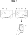
- FIG. 9 is a diagram illustrating a method of displaying a UI screen corresponding to a type of a user interaction according to an embodiment of the disclosure.
- the one or more processor 150 when the user is identified as being located in a preset zone according to an embodiment, the one or more processor 150, if a signal corresponding to a tap input is received from the user terminal 200 through the communication interface 130, the one or more processor 150 may control the display 110 to display a UI screen corresponding to the tap input.
- the one or more processor 150 may control the display 110 to display a UI screen 920 including an image 921 displayed through the existing display 110 and an image 922 displayed through a display (not shown) of the user terminal 200, respectively.
- FIGS. 10A to 10B are diagrams illustrating a method of displaying a UI screen corresponding to a type of a user interaction according to an embodiment of the disclosure.
- the UI screen 1010 displayed on the display 110 is a UI screen for moving a channel. If a signal corresponding to the shake interaction is received from the user terminal 200 while being displayed on the above-described UI screen, the one or more processor 150 may identify that the control command corresponding to the shake interaction is a command for controlling a UI screen provided from the user terminal 200.
- the one or more processor 150 may transmit a control signal for providing, from the user terminal 200 to the user terminal 200 through the communication interface 130, a UI screen 1020 recommending channels frequently used by the user, as shown in FIG. 10B . Accordingly, the user may easily change the channel of the electronic apparatus 100 through the user terminal 200.
- a UI screen corresponding to the content displayed on the display 110 e control signal may be transmitted to the user terminal 200 through the communication interface 130.
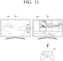
- FIG. 11 is a diagram illustrating a method of displaying a UI screen corresponding to a type of a user interaction according to an embodiment of the disclosure.
- a signal corresponding to the tap input is received from the user terminal 200 through the communication interface 130.
- the user terminal 200 may be a game console.
- the one or more processor 150 may control the display 110 to display a UI screen 1120 corresponding to a console game selection instead of the image 1110 displayed through the conventional display 110 as a signal corresponding to a tap input is received.
- a signal corresponding to the tap input may be received together with type information of the user terminal 200.
- the one or more processor 150 may identify an external input (e.g., when a game player is connected) to identify that the user terminal 200 is a game console and perform a corresponding function. Accordingly, the user may play the game by simply connecting the user terminal 200 and the electronic apparatus 100 with only tap interaction.
- an external input e.g., when a game player is connected
- FIGS. 12a to 12b are diagrams illustrating a method of displaying a UI screen corresponding to a type of a user interaction according to an embodiment of the disclosure.
- the UI screen 1210 displayed on the display 110 may be a UI screen for the user to play a game. If a signal corresponding to the shake interaction is received from the user terminal 200 while being displayed on the above-described UI screen, the one or more processor 150 may identify that the control command corresponding to the shake interaction is a command to control the UI screen provided from the user terminal 200.
- the one or more processor 150 may recommend a frequently played game to the user as shown in FIG. 12b , and may transmit a control signal for providing a UI screen 1220 by the user terminal 200 to connect the user terminal 200 and the electronic apparatus 100 to the user terminal 200 through the communication interface 130.
- the one or more processor 150 may transmit a control signal to provide the UI screen 1230 corresponding to the game controller by the user terminal 200 to the user terminal 200 through the communication interface 130.
- the user may conveniently connect the user terminal 200 and the electronic apparatus 100 with only user interaction without a separate user input.
- FIGS. 13a to 13b are diagrams illustrating a method of displaying a UI screen according to a type of a user interaction according to an embodiment of the disclosure.
- the UI screen 1310 displayed on the display 110 may be a UI screen for the user to chat online. If a signal corresponding to the shake interaction is received from the user terminal 200 while the UI screen 1310 is displayed, the one or more processor 150 may identify that the control command corresponding to the shake interaction is the command for controlling the UI screen provided by the user terminal 200.
- the one or more processor 150 may transmit a control signal to provide a UI screen 1320 for the user to input a chat through the user terminal 200 by the user terminal 200, as shown in FIG. 13b to the user terminal through the communication interface 130.
- FIG. 14 is a diagram illustrating a method of displaying a UI screen corresponding to a type of a user interaction according to an embodiment of the disclosure.
- the one or more processor 150 may control the display 110 to display a UI screen 1430 including an image 1432 obtained based on an image display through the display of the user terminal 200 along with the image 1431 displayed through the former display 110 as a signal corresponding to the tap input is received.
- the image 1420 displayed through the display (not shown) of the user terminal 200 and the image 1432 in the UI screen may be different.
- the one or more processor 150 may control the display 110 to display a UI screen 1430 including an image 1432 changed so that the sizes of the image of all people participating in the vide call are the same.
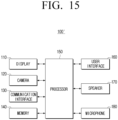
- FIG. 15 is a diagram illustrating a detailed configuration of an electronic apparatus according to an embodiment of the disclosure.
- an electronic apparatus 100' may include the display 110, the camera 120, the communication interface 130, the memory 140, the one or more processor 150, a user interface 160, a speaker 170, and a microphone 180.
- the display 110 the camera 120, the communication interface 130, the memory 140, the one or more processor 150, a user interface 160, a speaker 170, and a microphone 180.
- the components shown in FIG. 15 detailed descriptions of components overlapping those shown in FIG. 2 will be omitted.
- the user interface 160 is configured to be involved in performing interaction with the user by the electronic apparatus 100'.
- the user interface 160 may include at least one of a touch sensor, a motion sensor, a button, a jog dial, a switch, a microphone, or a speaker, but is not limited thereto.
- the speaker 170 may include a tweeter for playing a high-pitched sound band sound, a mid-range for playing a middle-range sound band sound, a woofer for playing a low-pitched sound band sound, a subwoofer for playing a very low-pitched sound band sound, an enclosure for controlling resonance, a crossover network for dividing an electric signal frequency inputted to the speaker for each band, and the like.
- the speaker 170 may output the sound signal to the outside of the electronic apparatus 100'.
- the speaker 170 may output multimedia playback, recording playback, various notification sounds, voice messages, and the like.
- the electronic apparatus 100' may include an audio output device such as the speaker 170, but may include an output device such as an audio output terminal.
- the speaker 170 may provide obtained information, information processed/produced based on the obtained information, a response result of a user voice, or an operation result in a voice form.
- the microphone 180 may refer to a module for obtaining a sound and converting the sound into an electrical signal, and may be a condenser microphone, a ribbon microphone, a moving coil microphone, a piezoelectric element microphone, a carbon microphone, and a Micro Electro Mechanical System (MEMS) microphone.
- the microphone may be implemented in the manner of omnidirectional, bi-directional, unidirectional, sub-cardioid, super cardioid, hyper cardioid, or the like.
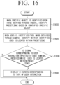
- FIG. 16 is a flowchart illustrating a control method of an electronic apparatus according to an embodiment of the disclosure.
- a preset zone is identified based on the identified specific object in operation S1610.
- operation S1610 may include the steps of displaying an image including a specific object, displaying a UI screen for setting a preset zone in the displayed image, and identifying a preset zone based on the user command input through the displayed UI screen.
- operation S1610 when it is identified that the identified user is located in a preset zone for a threshold time or longer, it may be identified that a user is located within a preset zone.
- operation S1610 may include the steps of displaying an image including a plurality of specific objects displaying a UI screen for setting a preset zone corresponding to each of a plurality of specific objects in the displayed image, and identifying a preset zone corresponding to each of the plurality of specific objects based on the user command inputted through the displayed UI screen.
- operation S1620 it may be identified whether the user terminal is located within a preset zone based on the RSSI size information of a signal periodically received from the user terminal, and it may be identified that the user is located within a preset zone when it is identified that the user terminal is located within the preset zone.
- a UI screen corresponding to the type of the user interaction is displayed in operation S1640.
- the UI screen corresponding to a type of the user interaction may be a UI screen for providing multi device experience (MDE).
- control method may further include the steps of: storing information on a plurality of preset zones mapped to face information of a plurality of users in a memory; obtaining information on a plurality of preset zones mapped to face information of a first user among face information of the plurality of users when face information of the first user is identified in the image obtained through the camera; and identifying whether the face information of the first user is located within a plurality of preset zones.
- control method may further include identifying a control command corresponding to the type of user interaction and, when the identified control command is a command for controlling a UI screen provided from a user terminal, transmitting a UI corresponding to the content displayed on the display to the user terminal to provide the UI screen on the user terminal.
- a UI screen indicating a region identified based on each of a plurality of specific objects is displayed, and in operation S1610, at least one region selected based on a user command among regions identified based on each of a plurality of specific objects as a preset zone.
- operation S1610 when a specific object is identified in the first image obtained through the camera, a preset zone is identified based on the identified specific object, and information on the identified preset zone is transmitted.
- operation S1620 when the user is identified in the second image obtained through the camera, it is possible to identify whether the identified user is located in the preset zone based on information about the preset zone stored in the memory.
- FIG. 17 is a flowchart to describe a control method of an electronic apparatus according to an embodiment of the disclosure.
- the one or more processor 150 receives a signal corresponding to a user interaction from the user terminal 200 in operation S1710.
- the type of user interaction may be at least one of a tap interaction and a shake interaction.
- the one or more processor 150 identifies whether the user 10 is located within a preset zone in operation S1720. According to an example, the one or more processor 150 may identify whether the user 10 is located within a preset zone based on whether the skeleton corresponding to the user 10 is included in a preset zone by obtaining information about a preset zone through the memory 140 and identifying whether the user 10 is present through the image obtained through the camera 120 and location of skeleton corresponding to the user 10.
- the one or more processor 150 may receive a signal corresponding to the content provided by the user terminal 200 according to an embodiment in operation S1730.
- the one or more processor 150 may provide a UI screen corresponding to the user interaction in operation S1740. For example, when a signal corresponding to a tap input is received, the one or more processor 150 may control the display 110 to provide a UI screen including a screen displayed through the display 110 and a UI screen for mirroring the user terminal 200, respectively.
- FIG. 18 is a diagram illustrating a method of providing a UI screen to a user according to an embodiment of the disclosure.
- the electronic apparatus 100 may identify whether the user is located within a preset zone by considering both the BLE broadcasting signal and the image obtained through the camera.
- the electronic apparatus 100 periodically emits a BLE broadcasting signal in operation S1810.
- the signal emission period may be a preset value (e.g., 3 seconds or 5 seconds), but is not limited thereto.
- the user terminal 200 when the user terminal 200 receives the BLE broadcasting signal emitted from the electronic apparatus 100 in operation S1815, the user terminal 200 transmits RSSI size information corresponding to the received BLE broadcasting signal to the electronic apparatus 100 in operation S1820.
- the electronic apparatus 100 identifies the user based on the image obtained through the camera 120 in operation S1830.
- the size information of the threshold value may be pre-stored in the memory 140 at the time of initial setting, but is not limited thereto, and may be changed based on user input.
- the electronic apparatus 100 transmits a signal for starting detection of user interaction to the user terminal 200 in operation S1840, and the user terminal 200 starts sensing the user interaction accordingly in operation S1845.
- the user terminal 200 transmits a signal corresponding to the detected user interaction to the electronic apparatus 100 in operation S1855.
- the electronic apparatus 100 identifies context information of the electronic apparatus 100 at the time the signal is received in operation S1860.
- the context information is information about the content displayed on the electronic apparatus 100, and may include, for example, the type of content, the content provider, whether or not subtitles are provided for the content, and the like.
- the electronic apparatus 100 displays a UI screen corresponding to the type of user interaction in operation S1865, and transmits a control signal to provide a UI screen corresponding to the content displayed on the electronic apparatus 100 to the user terminal 200 in operation S1870. For example, when a tap interaction is received, the electronic apparatus 100 displays a UI screen on which an online chatting application is executed, and transmits a control signal to provide a UI screen for inputting a chat to the user terminal 200 from the user terminal 200.
- the user terminal 200 When a control signal is received from the electronic apparatus 100, the user terminal 200 displays a UI screen corresponding to the displayed content of the electronic apparatus 100 in operation S1875. For example, when the UI screen displayed on the electronic apparatus 100 is a UI screen for a user to chat online, the user terminal 200 receives a control signal to provide a UI screen for inputting a chat on the user terminal 200 from the electronic apparatus 100 and may display a UI screen to input chatting.
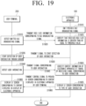
- FIG. 19 is a diagram illustrating a method of providing a UI screen to a user according to an embodiment of the disclosure.
- the electronic apparatus 100 may identify whether a user is located within a preset zone in consideration of only the BLE broadcasting signal.
- the electronic apparatus 100 periodically emits a BLE broadcasting signal in operation S1910. Then, when the user terminal 200 receives the BLE broadcasting signal emitted from the electronic apparatus 100 in operation S1915, the user terminal 200 transmits RSSI size information corresponding to the received BLE broadcasting signal to the electronic apparatus 100 in operation S1920.
- the electronic apparatus 100 transmits a signal for starting detection of user interaction to the user terminal 200 in operation S1930, and the user terminal 200 accordingly starts sensing the user interaction in operation S1935.
- the user terminal 200 transmits a signal corresponding to the detected user interaction to the electronic apparatus 100 in operation S1945.
- the electronic apparatus 100 identifies context information of the electronic apparatus 100 at the time when the signal corresponding to the user interaction is received in operation S1950.
- the electronic apparatus 100 displays a UI screen corresponding to the type of user interaction in operation S1955, and provides a control signal to provide a UI screen corresponding to the content displayed on the electronic apparatus 100 in the user terminal 200 to the user terminal 200 in operation S1960.
- the user terminal 200 displays a UI screen corresponding to the content displayed on the electronic apparatus 100 in operation S1965.
- a zone may be set in consideration of an image obtained through a camera, and an electronic apparatus and an external device may be connected in consideration of information about the set zone and the location of the identified user. Accordingly, it is possible to communicate with the external device efficiently, and the occurrence of misrecognition and malfunction occurring during communication with the external device may be reduced.
- the methods according to various embodiments of the disclosure described above may be implemented in the form of an application that may be installed in an existing electronic apparatus.
- the above-described methods according to various embodiments of the disclosure may be performed using a deep learning-based artificial neural network (or deep artificial neural network), that is, a learning network model.
- the methods according to various embodiments of the disclosure described above may be implemented by software upgrade or hardware upgrade for an existing electronic apparatus.
- various embodiments of the disclosure described above may be performed through an embedded server provided in the electronic apparatus or an external server of the electronic apparatus.
- the various embodiments described above may be implemented as software including instructions stored in a machine-readable storage media which is readable by a machine (e.g., a computer).
- the device may include a display device (e.g., display device A) according to the disclosed embodiments, as a device which calls the stored instructions from the storage media and which is operable according to the called instructions.
- the one or more processor may perform functions corresponding to the instructions using other components or the functions may be performed under a control of the one or more processor.
- the instructions may include code generated by a compiler or a code executed by an interpreter.
- the machine-readable storage media may be provided in a form of a non-transitory storage media.
- the 'non-transitory' storage media may not include a signal and is tangible, but does not distinguish whether data is stored semi-permanently or temporarily in the storage media.
- a method may be provided included a computer program product.
- the computer program product may be exchanged between a seller and a purchaser as a commodity.
- the computer program product may be distributed in the form of a machine-readable storage medium (e.g., a compact disc read only memory (CD-ROM)), or distributed online through an application store (e.g., PLAYSTORE TM ).
- an application store e.g., PLAYSTORE TM
- at least a portion of the computer program product e.g., downloadable app
- each of the components may be include a single entity or a plurality of entities, and some subcomponents of the above-mentioned subcomponents may be omitted or the other subcomponents may be further included to the various embodiments.
- some components e.g., modules or programs
Landscapes
- Engineering & Computer Science (AREA)
- Theoretical Computer Science (AREA)
- Physics & Mathematics (AREA)
- General Physics & Mathematics (AREA)
- Human Computer Interaction (AREA)
- General Engineering & Computer Science (AREA)
- Multimedia (AREA)
- Health & Medical Sciences (AREA)
- General Health & Medical Sciences (AREA)
- Signal Processing (AREA)
- Computer Networks & Wireless Communication (AREA)
- Computer Hardware Design (AREA)
- Oral & Maxillofacial Surgery (AREA)
- Nonlinear Science (AREA)
- Social Psychology (AREA)
- Crystallography & Structural Chemistry (AREA)
- Optics & Photonics (AREA)
- Quality & Reliability (AREA)
- Electromagnetism (AREA)
- Chemical & Material Sciences (AREA)
- Databases & Information Systems (AREA)
- Mathematical Physics (AREA)
- User Interface Of Digital Computer (AREA)
Applications Claiming Priority (3)
| Application Number | Priority Date | Filing Date | Title |
|---|---|---|---|
| KR20220043058 | 2022-04-06 | ||
| KR1020220065432A KR20230143900A (ko) | 2022-04-06 | 2022-05-27 | 전자 장치 및 이의 제어 방법 |
| PCT/KR2023/003528 WO2023195650A1 (ko) | 2022-04-06 | 2023-03-16 | 전자 장치 및 이의 제어 방법 |
Publications (2)
| Publication Number | Publication Date |
|---|---|
| EP4435565A1 true EP4435565A1 (de) | 2024-09-25 |
| EP4435565A4 EP4435565A4 (de) | 2025-05-07 |
Family
ID=88243018
Family Applications (1)
| Application Number | Title | Priority Date | Filing Date |
|---|---|---|---|
| EP23784878.3A Pending EP4435565A4 (de) | 2022-04-06 | 2023-03-16 | Elektronische vorrichtung und steuerungsverfahren dafür |
Country Status (4)
| Country | Link |
|---|---|
| US (1) | US20240069703A1 (de) |
| EP (1) | EP4435565A4 (de) |
| CN (1) | CN119234197A (de) |
| WO (1) | WO2023195650A1 (de) |
Family Cites Families (7)
| Publication number | Priority date | Publication date | Assignee | Title |
|---|---|---|---|---|
| CN102822627B (zh) * | 2010-03-26 | 2016-08-03 | 联想创新有限公司(香港) | 位置测量设备和用于产生位置信息的方法 |
| KR101609861B1 (ko) * | 2010-11-16 | 2016-04-20 | 주식회사 케이티 | 사용자 동작에 기초한 입력 제어 시스템 및 방법 |
| JP6167529B2 (ja) * | 2013-01-16 | 2017-07-26 | 株式会社リコー | 画像投影装置、画像投影システム、制御方法およびプログラム |
| KR20150046594A (ko) * | 2013-10-22 | 2015-04-30 | 삼성전자주식회사 | 단말 장치 및 제어 방법 |
| KR102246120B1 (ko) * | 2014-11-21 | 2021-04-29 | 삼성전자주식회사 | 디스플레이 장치를 제어하기 위한 사용자 단말 및 이의 제어 방법 |
| KR20190045501A (ko) * | 2017-10-24 | 2019-05-03 | 한밭대학교 산학협력단 | 스마트기기 무선 통신과 파라볼라 안테나를 이용한 게이트 자동인증 시스템 |
| EP3502838B1 (de) * | 2017-12-22 | 2023-08-02 | Nokia Technologies Oy | Vorrichtung, verfahren und system zur identifizierung eines zielobjekts aus einer vielzahl von objekten |
-
2023
- 2023-03-16 EP EP23784878.3A patent/EP4435565A4/de active Pending
- 2023-03-16 WO PCT/KR2023/003528 patent/WO2023195650A1/ko not_active Ceased
- 2023-03-16 CN CN202380023739.1A patent/CN119234197A/zh active Pending
- 2023-11-06 US US18/387,268 patent/US20240069703A1/en active Pending
Also Published As
| Publication number | Publication date |
|---|---|
| EP4435565A4 (de) | 2025-05-07 |
| US20240069703A1 (en) | 2024-02-29 |
| WO2023195650A1 (ko) | 2023-10-12 |
| CN119234197A (zh) | 2024-12-31 |
Similar Documents
| Publication | Publication Date | Title |
|---|---|---|
| US11164546B2 (en) | HMD device and method for controlling same | |
| KR20190124189A (ko) | 사용자 단말 장치 및 이의 디스플레이 방법 | |
| US20170148376A1 (en) | Electronic apparatus, distance measurement sensor and control method for electronic apparatus and distance measurement sensor | |
| JP6400293B2 (ja) | 電子装置でコンテンツを制御する装置及びその方法 | |
| KR20170060485A (ko) | 표시 모드에 따른 콘텐트를 표시하기 위한 전자 장치 및 방법 | |
| US10802784B2 (en) | Transmission of data related to an indicator between a user terminal device and a head mounted display and method for controlling the transmission of data | |
| CN108510929B (zh) | 一种显示装置及其控制方法 | |
| CN105589732A (zh) | 通过虚拟环境共享信息的设备和方法 | |
| US20190012129A1 (en) | Display apparatus and method for controlling display apparatus | |
| KR102308192B1 (ko) | 디스플레이 장치 및 그 제어 방법 | |
| US20180174356A1 (en) | Display apparatus and control method thereof | |
| US9875075B1 (en) | Presentation of content on a video display and a headset display | |
| CN103716686A (zh) | 显示设备、终端设备、外部设备以及显示和数据接收方法 | |
| US11670022B2 (en) | Electronic device and method for displaying and generating panoramic image | |
| KR102005406B1 (ko) | 디스플레이 장치 및 그 제어 방법 | |
| CN108293108A (zh) | 用于显示并生成全景图像的电子装置和方法 | |
| KR20180028320A (ko) | 디스플레이 장치 및 이의 제어 방법 | |
| JP2013015741A (ja) | 画像出力装置、画像出力方法、およびプログラム | |
| EP4435565A1 (de) | Elektronische vorrichtung und steuerungsverfahren dafür | |
| CN106534061B (zh) | 电子设备和用于控制电子设备的方法 | |
| KR20230143900A (ko) | 전자 장치 및 이의 제어 방법 | |
| EP3837850B1 (de) | Anzeigeapparat, server, elektronischer apparat und zugehörige steuerungsverfahren | |
| EP3128397A1 (de) | Elektronische vorrichtung und texteingabeverfahren dafür | |
| TWM628625U (zh) | 3d顯示系統 | |
| US12567180B2 (en) | Electronic apparatus and controlling method for automatically generating virtual space corresponding to items of avatar |
Legal Events
| Date | Code | Title | Description |
|---|---|---|---|
| STAA | Information on the status of an ep patent application or granted ep patent |
Free format text: STATUS: THE INTERNATIONAL PUBLICATION HAS BEEN MADE |
|
| PUAI | Public reference made under article 153(3) epc to a published international application that has entered the european phase |
Free format text: ORIGINAL CODE: 0009012 |
|
| STAA | Information on the status of an ep patent application or granted ep patent |
Free format text: STATUS: REQUEST FOR EXAMINATION WAS MADE |
|
| 17P | Request for examination filed |
Effective date: 20240617 |
|
| AK | Designated contracting states |
Kind code of ref document: A1 Designated state(s): AL AT BE BG CH CY CZ DE DK EE ES FI FR GB GR HR HU IE IS IT LI LT LU LV MC ME MK MT NL NO PL PT RO RS SE SI SK SM TR |
|
| A4 | Supplementary search report drawn up and despatched |
Effective date: 20250409 |
|
| RIC1 | Information provided on ipc code assigned before grant |
Ipc: G06V 40/16 20220101ALI20250403BHEP Ipc: G06F 3/14 20060101ALI20250403BHEP Ipc: G06F 3/0484 20220101ALI20250403BHEP Ipc: H04B 17/318 20150101ALI20250403BHEP Ipc: G02F 1/1333 20060101ALI20250403BHEP Ipc: H10K 59/40 20230101ALI20250403BHEP Ipc: G06F 3/00 20060101ALI20250403BHEP Ipc: G06F 3/01 20060101AFI20250403BHEP |
|
| DAV | Request for validation of the european patent (deleted) | ||
| DAX | Request for extension of the european patent (deleted) |