EP4436013A1 - Moteur à rotor noyé - Google Patents
Moteur à rotor noyé Download PDFInfo
- Publication number
- EP4436013A1 EP4436013A1 EP24162601.9A EP24162601A EP4436013A1 EP 4436013 A1 EP4436013 A1 EP 4436013A1 EP 24162601 A EP24162601 A EP 24162601A EP 4436013 A1 EP4436013 A1 EP 4436013A1
- Authority
- EP
- European Patent Office
- Prior art keywords
- support sleeve
- stator
- rotor motor
- wet
- wet rotor
- Prior art date
- Legal status (The legal status is an assumption and is not a legal conclusion. Google has not performed a legal analysis and makes no representation as to the accuracy of the status listed.)
- Pending
Links
Images

Classifications
-
- H—ELECTRICITY
- H02—GENERATION; CONVERSION OR DISTRIBUTION OF ELECTRIC POWER
- H02K—DYNAMO-ELECTRIC MACHINES
- H02K5/00—Casings; Enclosures; Supports
- H02K5/04—Casings or enclosures characterised by the shape, form or construction thereof
- H02K5/12—Casings or enclosures characterised by the shape, form or construction thereof specially adapted for operating in liquid or gas
- H02K5/128—Casings or enclosures characterised by the shape, form or construction thereof specially adapted for operating in liquid or gas using air-gap sleeves or air-gap discs
-
- H—ELECTRICITY
- H02—GENERATION; CONVERSION OR DISTRIBUTION OF ELECTRIC POWER
- H02K—DYNAMO-ELECTRIC MACHINES
- H02K2213/00—Specific aspects, not otherwise provided for and not covered by codes H02K2201/00 - H02K2211/00
- H02K2213/03—Machines characterised by numerical values, ranges, mathematical expressions or similar information
Definitions
- the invention relates to a wet rotor motor.
- gap tubes The requirements for such gap tubes are generally very high. For example, in certain applications the gap tube must withstand high pressures of over 100 bar over a long period of time. Furthermore, such gap tubes must be made of electrically poorly or non-conductive material with small wall thicknesses, as otherwise the gap tube will negatively affect the magnetic flux between the stator and rotor, which will reduce the efficiency of the motor.
- the object of the invention is to provide a wet rotor motor which has a high efficiency and service life.
- the wet rotor motor has a rotor which can be rotated about a rotation axis and a stator which is arranged radially outside the rotor with respect to the rotation axis. Furthermore, the wet rotor motor has a can which is arranged in an air gap between the stator and the rotor and in particular on the stator The can has at least one end region which projects axially beyond the stator with respect to the axis of rotation. The wet rotor motor has at least one support sleeve which is arranged on the at least one end region and is designed to protect at least part of the end region against internal pressures in the can.
- the wet rotor motor is flooded with a fluid, such as oil, during operation.
- the rotor in particular is flooded with the fluid.
- the can rests against the stator, in particular due to the internal pressures during operation of the wet-running motor.
- the can can be radially spaced from the stator when the wet-running motor is at rest, in which there is little to no internal pressure in the can.
- the can can also rest against the stator when the wet-running motor is at rest. While the can rests against the stator, it is advantageously supported by the stator, so that the can is supported by the stator against internal pressures from the fluid in the areas that rest against the stator.
- the can in particular in conjunction with the support sleeve, advantageously fixes the stator.
- the can can also be protected at its end areas against internal pressures in the can, so that the service life of the wet rotor motor is increased. This also makes it possible to advantageously reduce or keep the wall thickness of the can low, so that magnetic fluxes between the rotor and the stator are less negatively influenced by the can and the efficiency of the wet rotor motor can be increased.
- the support sleeve completely encloses a circumference of the respective end region.
- the support sleeve is preferably designed as a tube. This ensures that the support sleeve has a particularly good supporting effect.
- the support sleeve only partially encloses the circumference of the respective end area.
- the support sleeve is designed as a slotted tube with an elongated slot. This makes it particularly easy to place the support sleeve on the slotted tube.
- the support sleeve is advantageously arranged on an outer circumferential surface of the respective end area of the split tube.
- the support sleeve therefore supports the end area against internal pressure in the split tube. This also ensures particularly simple assembly.
- the support sleeve is arranged on an inner circumferential surface of the respective end region. As a result, the support sleeve absorbs the internal pressures in the can instead of the end region of the can.
- the wet rotor motor advantageously has a plurality of support sleeves for at least one, in particular for each, end region of the can.
- a first support sleeve is advantageously arranged on the inner circumferential surface and a second support sleeve is arranged on the outer circumferential surface of the respective end region of the can. This ensures particularly good protection of the support tube.
- the support sleeve preferably has a lower end relative to the axis of rotation.
- the lower end of the support sleeve rests on an end face of the stator.
- the lower end of the support sleeve rests directly on the end face of the stator.
- the lower end of the support sleeve advantageously rests airtight on the end face of the stator.
- the support sleeve therefore advantageously provides continuous support for the can.
- the support sleeve preferably has an upper end with respect to the rotation axis, the upper end having a lip which rests on an end face of the can.
- the lip preferably rests directly on the end face of the can. It is particularly advantageous if the lip rests hermetically on the end face of the can. This avoids sharp edges on the can or covers them with the lip of the support sleeve. The lip thus ensures, particularly during an assembly process, that other components such as possible seals of the wet rotor motor are not damaged by a sharp edge of the can and/or that the can is not damaged during assembly.
- the support sleeve advantageously has a flange at its upper end and/or lower end. This advantageously allows a tolerance-compensating wave spring to rest against the flange. Furthermore, such a flange can provide a flat contact, for example with the stator, so that a particularly good and fluid-tight connection of the components can be ensured.
- the support sleeve has an insertion bevel.
- a minimum inner diameter of the insertion bevel is essentially equal to or less than an inner diameter of the can.
- an inner circumference of the insertion bevel is flush with an inner circumference of the can.
- the insertion bevel is advantageously formed at the upper end of the support sleeve.
- the insertion bevel advantageously ensures easy assembly of the wet rotor motor.
- the insertion bevel ensures that the Support sleeve, especially together with the split tube, can easily be guided past a seal during insertion without damaging the seal.
- an inner diameter of the stator is substantially equal to an inner diameter of the support sleeve.
- an inner circumference of the stator is advantageously flush with an inner circumference of the support sleeve. This allows for easy assembly and a secure connection between the components.
- stator and the support sleeve have the same tolerances so that an edge effect is advantageously avoided.
- essentially means in particular “within the scope of manufacturing tolerances” or “within the scope of the fit”.
- the aforementioned diameters are advantageously designed within the scope of manufacturing tolerances in such a way that a transition fit or a clearance fit is formed between the elements, in particular between the support sleeve and the can.
- the diameters/dimensions explained above and below refer to an installed state.
- the support sleeve and the split tube are designed in such a way that they form a transition fit. This enables particularly simple assembly and secure mounting of the support sleeve and/or the split tube.
- an outer circumference of the support sleeve has a taper along the axis of rotation.
- a wall thickness of the upper end of the support sleeve is greater than a wall thickness of the lower end of the support sleeve.
- the support sleeve has a wall thickness equal to or greater than that of the can. This also advantageously applies to the tapered area of the support sleeve. This enables particularly stable support by the support sleeve, while the wall thickness of the can can be reduced to increase the efficiency of the wet rotor motor.
- the support sleeve and the split tube advantageously comprise different materials from one another.
- the split tube comprises, in particular, fiber-reinforced plastic or is formed from this.
- the fiber-reinforced plastic is preferably carbon fiber-reinforced plastic (CFRP) and/or glass fiber-reinforced plastic (GFRP).
- CFRP carbon fiber-reinforced plastic
- GFRP glass fiber-reinforced plastic
- the support sleeve comprises, in particular, a metal or is formed from metal.
- the support sleeve and the split tube are advantageously separate elements.
- the support sleeve and the split tube are advantageously pushed into one another and held together at least temporarily, in particular by their fit, preferably a transition fit.
- the support sleeve and the split tube are advantageously one-piece.
- the support sleeve and the split tube are advantageously firmly connected to one another, for example glued or welded.
- the support sleeve and the split tube are advantageously connected to one another in a media-tight manner.
- the split tube and the possible support sleeve are glued or welded to one another on the inner circumferential surface of the end region of the split tube. This has the advantage that the medium in the split tube cannot get between the split tube and the support sleeve.
- the support sleeve and the split tube are made in one piece.
- the support sleeve is advantageously designed as a region of the split tube, in particular the end regions of the split tube, with a greater wall thickness than the other regions of the split tube.
- the support sleeve and the split tube are made in one piece from fiber-reinforced plastic, the support sleeve is formed by a larger plastic matrix and/or a higher number of fibers and/or by a higher number of fiber windings in the corresponding regions of the split tube.
- the invention also relates to the support sleeve according to one of the above particular embodiments.
- the invention also relates to the can according to one of the above special embodiments together with the support sleeve according to one of the above special embodiments.
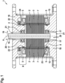
- Fig.1 shows a schematic cross-sectional view of a wet rotor motor 1 according to an embodiment of the present invention.
- Fig. 2 shows a perspective sectional view of the wet rotor motor 1 according to the embodiment of the present invention.
- the wet rotor motor 1 is in particular a fluid pump, advantageously an oil pump.
- Wet-running motor 1 is flooded with a fluid 20, here a conveying medium (for example oil) of the wet-running motor 1.
- a rotor 2 (explained below) of the wet-running motor 1 is flooded with the fluid 20.
- the wet rotor motor 1 has a rotor 2 that can be rotated about a rotation axis 6.
- the wet rotor motor 1 also has a stator 3 that is arranged radially outside the rotor 2 with respect to the rotation axis 6.
- the stator 3 and the rotor 2 are made of laminations made of stamped electrical steel, which are stacked as lamination packs.
- the stator 3 and/or the rotor 2 can be constructed monolithically from solid material.
- the rotor 2 is connected to a shaft 16.
- the shaft 16 is mounted on housing elements 18 of the wet-running motor 1 via bearings 17.
- the wet-running motor 1 also has a can 4, which is arranged in an air gap 7 between the stator 3 and the rotor 2.
- the housing elements 18 each have openings 21 for the fluid 20.
- the can 4 rests against the stator 3, in particular during operation of the wet-running motor 1.
- the can 4 rests against an inner circumference of the stator 3.
- the can 4 separates the rotor 2 and the stator 3 in a fluid-tight manner.
- the can 4 thus shields the stator 3 from the fluid 20.
- the wet-running motor 1 has seals 23 between the can 4 and the housing elements 18, which seal the housing elements 18.
- the gap tube 4 has two end regions 8 which protrude axially over the stator 3 with respect to the rotation axis 6.
- the gap tube 4 protrudes axially over the stator 3 with respect to the rotation axis 6 with both of its ends, ie in Fig.1 top and bottom, so that the split tube 4 in the present embodiment has two end regions 8.
- the fluid 20 surrounding the rotor 2 usually exerts high internal pressures along a radial direction 19 on the can 4.
- the can 4 is advantageously pressed radially against the stator 3 by the internal pressures.
- the can 4 can also already rest against the stator 3 in the resting state of the wet-running motor 1, in which there are no or low internal pressures.
- the can 4 is supported by the stator 3 in areas along the axis of rotation 6 in which the stator 3 is present.
- the wet rotor motor 1 also has at least one support sleeve 5, which is arranged on the at least one end region 8 and is designed to support the end region 8 against the internal pressures in the can 4.
- the support sleeve 5 is designed in particular with reference to Fig. 2 explained in more detail.
- the support sleeve 5 is arranged with a transition fit on an entire outer circumferential surface 9 of the end region 8 of the can 4.
- the support sleeve 5 has a lower end 10 which rests on an end face 11 of the stator 3.
- the lower end 10 of the support sleeve 5 rests directly, in particular airtight, on the end face 11 of the stator 3.
- the support sleeve 5 also has an upper end 12, which further has a lip 13, which rests on an upper end face 14 of the split tube 4.
- the lip 13 rests in particular directly on the end face 14 of the split tube 4.
- the lip 13 is part of an insertion bevel 15 of the support sleeve 5.
- a minimum inner diameter of the insertion bevel 15, i.e. at the location of the lip 13, is in the present embodiment essentially equal to an inner diameter of the split tube 4. In other words, the lip 13 is flush with the split tube 4.
- the insertion bevel 15 of the support sleeve 5 allows easy insertion of the seals 23 (see Fig.1 ).
- the insertion bevel 15 of the support sleeve 5 ensures that they can slide past the seals 23 without damaging the seals 23.
- a spring 22 is also arranged between the upper housing element 18 shown and the support sleeve 5.
- the support sleeve 5 advantageously has a flange 24 against which the spring 22 rests.
- the spring 22 is, for example, a wave spring.
- the spring 22 compensates for tolerances between the elements of the wet rotor motor 1. Furthermore, the spring 22, the support sleeve 5 and the can 4 together provide additional fixation of the stator 3.
- an inner diameter of the stator 3 is substantially equal to an inner diameter of the support sleeve 5. In other words, the stator 3 and the support sleeve 5 are flush.
- the support sleeve 5 has a structure tapering in the radial direction 19 along the rotation axis 6 from its upper end 12 to its lower end 10.
- the support sleeve 5 has a greater wall thickness than the can 4 throughout, particularly in the tapered area.
- the split tube 4 is made of a fiber-reinforced plastic.
- the split tube 4 is preferably made of carbon fiber reinforced plastic (CFRP) and/or glass fiber reinforced plastic (GFRP).
- CFRP carbon fiber reinforced plastic
- GFRP glass fiber reinforced plastic
- the support sleeve 5 is made of metal.
- the split tube 4 and the support sleeve 5 are designed as separate elements. Alternatively, however, they can be formed in one piece, for example by gluing and/or welding them. Alternatively, they can also be formed in one piece.
- the support sleeve 5 is also made of CFRP or GFRP and is formed as the end region 8 of the split tube 4.
Landscapes
- Engineering & Computer Science (AREA)
- Power Engineering (AREA)
- Motor Or Generator Frames (AREA)
Applications Claiming Priority (1)
| Application Number | Priority Date | Filing Date | Title |
|---|---|---|---|
| DE102023107104.1A DE102023107104A1 (de) | 2023-03-21 | 2023-03-21 | Nassläufermotor |
Publications (1)
| Publication Number | Publication Date |
|---|---|
| EP4436013A1 true EP4436013A1 (fr) | 2024-09-25 |
Family
ID=90364948
Family Applications (1)
| Application Number | Title | Priority Date | Filing Date |
|---|---|---|---|
| EP24162601.9A Pending EP4436013A1 (fr) | 2023-03-21 | 2024-03-11 | Moteur à rotor noyé |
Country Status (3)
| Country | Link |
|---|---|
| EP (1) | EP4436013A1 (fr) |
| CN (1) | CN118694069A (fr) |
| DE (1) | DE102023107104A1 (fr) |
Citations (7)
| Publication number | Priority date | Publication date | Assignee | Title |
|---|---|---|---|---|
| JPS55145852U (fr) * | 1979-04-04 | 1980-10-20 | ||
| JPH06276713A (ja) * | 1993-03-16 | 1994-09-30 | Mayekawa Mfg Co Ltd | キャンドモータのキャン形成方法 |
| JPH0735074A (ja) * | 1993-07-23 | 1995-02-03 | Mayekawa Mfg Co Ltd | キャンドモータを用いたアンモニヤ冷媒用回転圧縮装置及びその運転方法 |
| EP2365614A2 (fr) * | 2010-03-13 | 2011-09-14 | KSB Aktiengesellschaft | Moteur à gaine avec support de gaine |
| JP5555510B2 (ja) * | 2010-03-12 | 2014-07-23 | 株式会社荏原製作所 | キャンドモータ及びキャンドモータポンプ |
| DE102013109522B4 (de) | 2013-09-02 | 2015-06-18 | Rausch & Pausch Gmbh | Spaltrohrmotor mit hochdruckfestem Spaltrohr |
| DE102021120993A1 (de) * | 2021-08-12 | 2023-02-16 | Dr. Ing. H.C. F. Porsche Aktiengesellschaft | Elektrische Maschine und Kraftfahrzeug |
-
2023
- 2023-03-21 DE DE102023107104.1A patent/DE102023107104A1/de active Pending
-
2024
- 2024-01-09 CN CN202410029920.XA patent/CN118694069A/zh active Pending
- 2024-03-11 EP EP24162601.9A patent/EP4436013A1/fr active Pending
Patent Citations (7)
| Publication number | Priority date | Publication date | Assignee | Title |
|---|---|---|---|---|
| JPS55145852U (fr) * | 1979-04-04 | 1980-10-20 | ||
| JPH06276713A (ja) * | 1993-03-16 | 1994-09-30 | Mayekawa Mfg Co Ltd | キャンドモータのキャン形成方法 |
| JPH0735074A (ja) * | 1993-07-23 | 1995-02-03 | Mayekawa Mfg Co Ltd | キャンドモータを用いたアンモニヤ冷媒用回転圧縮装置及びその運転方法 |
| JP5555510B2 (ja) * | 2010-03-12 | 2014-07-23 | 株式会社荏原製作所 | キャンドモータ及びキャンドモータポンプ |
| EP2365614A2 (fr) * | 2010-03-13 | 2011-09-14 | KSB Aktiengesellschaft | Moteur à gaine avec support de gaine |
| DE102013109522B4 (de) | 2013-09-02 | 2015-06-18 | Rausch & Pausch Gmbh | Spaltrohrmotor mit hochdruckfestem Spaltrohr |
| DE102021120993A1 (de) * | 2021-08-12 | 2023-02-16 | Dr. Ing. H.C. F. Porsche Aktiengesellschaft | Elektrische Maschine und Kraftfahrzeug |
Also Published As
| Publication number | Publication date |
|---|---|
| DE102023107104A1 (de) | 2024-09-26 |
| CN118694069A (zh) | 2024-09-24 |
Similar Documents
| Publication | Publication Date | Title |
|---|---|---|
| DE69009346T2 (de) | Elektrische Motorpumpe mit Spaltrohr. | |
| WO2018162282A1 (fr) | Moteur électrique | |
| DE102009019936A1 (de) | Fluiddynamisches Lagersystem | |
| DE3614748A1 (de) | Elektromotor, insbesondere kollektorloser gleichstrommotor, mit einem aussenrotor | |
| DE102008031618A1 (de) | Fluiddynamisches Lager | |
| DE102017203833A1 (de) | Flüssigkeitspumpe | |
| DE102018111993A1 (de) | Rotor mit einer Endscheibenanordnung | |
| DE102019112830A1 (de) | Spaltrohrmotor mit erhöhtem Wirkungsgrad | |
| DE102011014369A1 (de) | Fluiddynamisches Lagersystem | |
| EP1286055A1 (fr) | Pompe à rotor mouillé | |
| DE102008025618A1 (de) | Fluiddynamisches Lagersystem | |
| DE102021120993A1 (de) | Elektrische Maschine und Kraftfahrzeug | |
| DE102011016888A1 (de) | Fluiddynamisches Lagersystem | |
| DE102014205599A1 (de) | Kühlhülse für ein Lager und Lager mit Kühlhülse | |
| DE3629049A1 (de) | Stator fuer einen aussenlaeufermotor | |
| EP2728194B1 (fr) | Pompe à vide et méthode de fabrication d'une pompe à vide | |
| EP4436013A1 (fr) | Moteur à rotor noyé | |
| DE102009022997B4 (de) | Spindelmotor mit fluiddynamischem Lagersystem und feststehender Welle | |
| DE102015106614A1 (de) | Pumpenvorrichtung | |
| DE102017118871A1 (de) | Fluiddynamisches Lagersystem | |
| EP4325061B1 (fr) | Pompe à vide turbomoléculaire | |
| DE202008017587U1 (de) | Rotor | |
| DE102019215454A1 (de) | Elektrische Maschine | |
| DE102008033361A1 (de) | Spindelmotor mit hydrodynamischem Lagersystem | |
| DE102022207816A1 (de) | Anordnung zur Erdung einer Welle |
Legal Events
| Date | Code | Title | Description |
|---|---|---|---|
| PUAI | Public reference made under article 153(3) epc to a published international application that has entered the european phase |
Free format text: ORIGINAL CODE: 0009012 |
|
| STAA | Information on the status of an ep patent application or granted ep patent |
Free format text: STATUS: THE APPLICATION HAS BEEN PUBLISHED |
|
| AK | Designated contracting states |
Kind code of ref document: A1 Designated state(s): AL AT BE BG CH CY CZ DE DK EE ES FI FR GB GR HR HU IE IS IT LI LT LU LV MC ME MK MT NL NO PL PT RO RS SE SI SK SM TR |
|
| STAA | Information on the status of an ep patent application or granted ep patent |
Free format text: STATUS: REQUEST FOR EXAMINATION WAS MADE |
|
| 17P | Request for examination filed |
Effective date: 20250325 |