EP4436037A1 - Système de support - Google Patents
Système de support Download PDFInfo
- Publication number
- EP4436037A1 EP4436037A1 EP24163850.1A EP24163850A EP4436037A1 EP 4436037 A1 EP4436037 A1 EP 4436037A1 EP 24163850 A EP24163850 A EP 24163850A EP 4436037 A1 EP4436037 A1 EP 4436037A1
- Authority
- EP
- European Patent Office
- Prior art keywords
- base body
- support structure
- base
- support frame
- support
- Prior art date
- Legal status (The legal status is an assumption and is not a legal conclusion. Google has not performed a legal analysis and makes no representation as to the accuracy of the status listed.)
- Pending
Links
- 239000000463 material Substances 0.000 claims abstract description 41
- 230000007246 mechanism Effects 0.000 claims description 8
- 238000004146 energy storage Methods 0.000 claims description 5
- 239000007788 liquid Substances 0.000 claims description 5
- 239000004575 stone Substances 0.000 claims description 5
- 239000013590 bulk material Substances 0.000 claims description 3
- 238000011161 development Methods 0.000 description 13
- 230000018109 developmental process Effects 0.000 description 13
- 230000008878 coupling Effects 0.000 description 6
- 238000010168 coupling process Methods 0.000 description 6
- 238000005859 coupling reaction Methods 0.000 description 6
- 239000007787 solid Substances 0.000 description 6
- 238000004873 anchoring Methods 0.000 description 3
- 238000013461 design Methods 0.000 description 3
- 238000012546 transfer Methods 0.000 description 3
- 230000000295 complement effect Effects 0.000 description 2
- 230000007613 environmental effect Effects 0.000 description 2
- 238000009434 installation Methods 0.000 description 2
- 230000007704 transition Effects 0.000 description 2
- 229910000831 Steel Inorganic materials 0.000 description 1
- 239000010426 asphalt Substances 0.000 description 1
- 230000015572 biosynthetic process Effects 0.000 description 1
- 239000000919 ceramic Substances 0.000 description 1
- 238000004140 cleaning Methods 0.000 description 1
- 239000002826 coolant Substances 0.000 description 1
- 230000000694 effects Effects 0.000 description 1
- 238000005538 encapsulation Methods 0.000 description 1
- 230000002349 favourable effect Effects 0.000 description 1
- 239000012530 fluid Substances 0.000 description 1
- 239000011796 hollow space material Substances 0.000 description 1
- 238000012423 maintenance Methods 0.000 description 1
- 238000004519 manufacturing process Methods 0.000 description 1
- 238000005259 measurement Methods 0.000 description 1
- 230000007935 neutral effect Effects 0.000 description 1
- 230000002093 peripheral effect Effects 0.000 description 1
- 230000005855 radiation Effects 0.000 description 1
- 230000000284 resting effect Effects 0.000 description 1
- 239000004576 sand Substances 0.000 description 1
- 238000004904 shortening Methods 0.000 description 1
- 239000010959 steel Substances 0.000 description 1
- 210000002435 tendon Anatomy 0.000 description 1
Images


Classifications
-
- H—ELECTRICITY
- H02—GENERATION; CONVERSION OR DISTRIBUTION OF ELECTRIC POWER
- H02S—GENERATION OF ELECTRIC POWER BY CONVERSION OF INFRARED RADIATION, VISIBLE LIGHT OR ULTRAVIOLET LIGHT, e.g. USING PHOTOVOLTAIC [PV] MODULES
- H02S20/00—Supporting structures for PV modules
- H02S20/30—Supporting structures being movable or adjustable, e.g. for angle adjustment
- H02S20/32—Supporting structures being movable or adjustable, e.g. for angle adjustment specially adapted for solar tracking
-
- F—MECHANICAL ENGINEERING; LIGHTING; HEATING; WEAPONS; BLASTING
- F24—HEATING; RANGES; VENTILATING
- F24S—SOLAR HEAT COLLECTORS; SOLAR HEAT SYSTEMS
- F24S30/00—Arrangements for moving or orienting solar heat collector modules
- F24S30/40—Arrangements for moving or orienting solar heat collector modules for rotary movement
- F24S30/45—Arrangements for moving or orienting solar heat collector modules for rotary movement with two rotation axes
- F24S30/452—Vertical primary axis
-
- F—MECHANICAL ENGINEERING; LIGHTING; HEATING; WEAPONS; BLASTING
- F24—HEATING; RANGES; VENTILATING
- F24S—SOLAR HEAT COLLECTORS; SOLAR HEAT SYSTEMS
- F24S30/00—Arrangements for moving or orienting solar heat collector modules
- F24S2030/10—Special components
- F24S2030/15—Bearings
Definitions
- the invention relates to a mounting system for a functional unit, in particular a photovoltaic module, with a floor-standing base and a support structure held on the base with a support frame for the functional unit.
- the functional unit supported by the mounting system is, for example, a photovoltaic module or a solar thermal module.
- the mounting system is designed as a photovoltaic or solar thermal system.
- the mounting system can be set up to mount other objects, e.g. a sign, an advertising board, a screen, a picture or another art object.
- the functional unit is held on the mounting system in an appropriate manner so that the desired visibility or orientation is achieved.
- Such mounting systems are set up in open spaces as well as on building roofs, such as house and garage roofs, or attached to building walls.
- the mounting systems can be rigid or rotatable.
- a rotatable mounting system for example, as a sun tracking system enables single-axis or two-axis tracking of the photovoltaic module depending on the position of the sun. In the version as a two-axis tracking mounting, rotation about a vertical and a horizontal axis is usually possible.
- the photovoltaic mounting system is typically oriented towards the south in its neutral position with respect to the vertical axis of rotation, so that it can rotate the same amount in both directions, i.e. towards the east and west, e.g. by 90° each.
- the support frame of the mounting system is designed to support the functional unit and forms an essentially flat frame, which typically consists of interconnected rods or supports and to which the functional unit can be detachably connected. This makes assembly and especially disassembly, e.g. if the functional unit is to be replaced, very simple in terms of the effort and tools required.
- the support structure of the elevation system establishes the connection between the floor-standing base and the functional unit and, if necessary, provides the desired rotation and/or pivoting mobility of the functional unit relative to the base.
- Conventional support structures often have the form of a framework that is designed in such a way that, on the one hand, it is lightweight in order to enable any required rotation or pivoting mobility without great energy expenditure, and, on the other hand, can transfer any forces that occur on the functional unit and/or the support structure to the base.
- the company RIB R ⁇ SER Ingenieurbeton offers the factory-set encapsulation of photovoltaic brackets in concrete foundations.
- the concrete foundations with the encapsulated brackets are then transported to the desired location and set up so that photovoltaic modules can be attached to the brackets.
- the disclosure document EN 10 2012 021 697 A1 discloses a support system with a mast that is founded on a truncated cone-shaped cistern in a building ground.
- the mast is stabilized by tendons that are connected to a stiffening ring at the upper edge of the cistern.
- Another conventional support system is described in the patent specification DE 101 92 244 B4 revealed.
- the invention is based on the technical problem of providing a mounting system of the type mentioned at the beginning, which can be set up in a particularly simple manner and can also be dismantled again if necessary and, when set up, Safe, stable support and optimal operation of the functional unit are ensured.
- the invention solves this problem by providing a mounting system with the features of claim 1.
- Advantageous developments of the invention are specified in the subclaims, the wording of which is hereby made part of the description by reference. This includes in particular all embodiments of the invention that result from the combinations of features that are defined by the references in the subclaims.
- the base includes a base body and the support structure includes a support structure.
- the base body can be designed as a hollow base body or as a solid base body.
- the support frame is pivotally articulated to the support structure about a horizontal pivot axis, and the support structure is held on the base body so that it can rotate about a vertical axis of rotation.
- the rotational mobility and the pivoting mobility enable a two-axis alignment of the support frame and thus of a functional unit held on it.
- the functional unit is a photovoltaic module or a solar thermal module, hereinafter summarized under the term solar module, this enables two-axis sun tracking and thus an optimal yield of the solar radiation.
- the rotational and pivoting mobility enables a suitable alignment of the support frame for purposes such as cleaning the functional unit held on it, assembling or disassembling the functional unit, clearing snow accumulated on the functional unit or turning the functional unit out of the wind and thereby freeing it from high wind loads.
- the support frame can be aligned in such a way that convenient access to the base and the area of the support structure close to the ground is possible without being obstructed by the support frame or a functional unit attached to it.
- the support structure supports the support frame and thus a functional unit carried on it and thus transfers forces and moments acting on the support frame and/or the functional unit to other components of the support system, in particular the base. Occurring forces and moments can be caused, for example, by The load can be caused by wind acting on the functional unit or a snow load on the functional unit.
- the support structure preferably comprises a plurality of beams, struts and/or suitably shaped support components which are connected to one another to form a framework.
- Rotating the support structure relative to the base causes the entire support structure to rotate around the vertical axis, i.e. the support structure, the support frame and possibly other components as well as a functional unit carried by the support frame. Pivoting the support frame relative to the support structure simultaneously causes a functional unit held on the support frame to pivot, while the support structure remains unmoved with respect to the pivoting.
- the support structure is freely rotatable relative to the base body or is held to a limited extent over a rotation angle range of at least 180°.
- Freely rotatable means that the support structure can be rotated relative to the base body in both directions of rotation without hindrance, i.e. by 360° or more. If the functional unit is a solar module, this enables optimal sun tracking with regard to the orientation around the vertical axis at any time of day or year. Furthermore, in cases where the support is on an agriculturally used area, the free rotation around the vertical axis can enable the functional unit to be rotated into a position that allows good use or accessibility of the area for agricultural equipment or commercial vehicles.
- the free rotation of the support structure also enables a view of the front of the functional unit from any direction, which can be desirable, for example, if the functional unit is an object that is on display.
- At least some of these advantages can be achieved in certain cases even if only a limited degree of rotation is available, e.g. from 0° to 180° or more or from 0° to at least 90° or more.
- the free or sufficiently large rotation allows access to the base or its foot from any direction without the functional unit hindering access. This can be helpful, for example, when mowing or other agricultural work on the area of land on which the support is installed, as the base can be driven directly up to. If several supports are facing each other, e.g. in several rows, the supports of two adjacent rows can be rotated away from each other so that an aisle is formed between them that essentially reaches up to the bases of the supports. In this case, this allows a maximum aisle width, which can make it easier to drive through with a vehicle such as a tractor with or without a trailer. In alternative designs, the support structure is limited in its rotational mobility relative to the base body by less than 180° if this is sufficient for the corresponding applications.
- the support structure is held on the base body by a rotary bearing extending in a ring around the vertical axis of rotation.
- a rotary bearing requires relatively little provision and is easy to assemble and is able to divert the forces acting on the support structure to the base body.
- the rotary bearing can have a closed ring shape or, alternatively, an open partial ring shape.
- the base body is column-shaped and the pivot bearing comprises an upper, ring-shaped pivot bearing unit and/or a lower, ring-shaped pivot bearing unit.
- the upper pivot bearing unit is located on an upper end face of the base body and the second pivot bearing unit is located on a column casing outside of the base body.
- the first pivot bearing unit can preferably be designed to absorb axial forces, while the second pivot bearing unit can easily absorb lateral forces and the torques caused by these around a horizontal axis due to its support on the base casing surface.
- the pivot bearing unit has only one of the two pivot bearing units. which absorbs all occurring forces and moments, or it has more than two rotary bearing units if this is appropriate for certain applications.
- the upper and lower pivot bearing units are arranged coaxially to one another and axially spaced from one another. This allows the support structure to be supported on the base at points that are axially spaced from one another. Accordingly, force loads can be diverted to the base at several points that are axially spaced from one another.
- the lower pivot bearing unit is arranged without an axial distance from the upper pivot bearing unit in an area of the base shell surface that borders the upper end face of the base body.
- the mounting system has a rotary drive for rotating the support structure around the vertical axis of rotation. This is coupled to the upper and/or lower rotary bearing unit.
- the rotary drive enables driven and, if necessary, automatic, i.e. self-acting, rotation or alignment of the support structure in relation to the base.
- the rotary drive is not coupled to one of the rotary bearing units, but directly to a component of the support structure, or the mounting system has no rotary drive at all and the support structure is manually rotated between different orientations.
- the lower pivot bearing unit comprises a plurality of pivot bearing rollers and a pivot bearing ring supported against the pivot bearing rollers.
- the pivot bearing rollers are attached to the outside of the column casing, and the pivot bearing ring is attached to a lower region of the support structure or is formed by the lower region of the support structure.
- the pivot bearing rollers are attached to the lower region of the support structure, and the pivot bearing ring is attached to the outside of the column casing or is formed by the outside of the column casing.
- the plurality of pivot bearing rollers in particular between four and sixteen, e.g. eight, are preferably arranged at equidistant intervals in the circumferential direction around the column casing surface, so that the support structure can be well supported on the base in all directions.
- the rotary bearing rollers comprise axially upwardly projecting first rotary bearing rollers on the outside of the column casing or in the lower region of the support structure and/or axially downwardly projecting second rotary bearing rollers on the outside of the column casing or in the lower region of the support structure and/or radially outwardly projecting third rotary bearing rollers on the outside of the column casing or in the lower region of the support structure and/or radially inwardly projecting fourth rotary bearing rollers on the outside of the column casing or in the lower region of the support structure.
- Pivot bearing rollers that protrude axially upwards or downwards, whose pivot bearing roller axes are then expediently oriented perpendicular to the axis of rotation of the support structure or to the vertical, are particularly suitable for absorbing forces in a vertical direction, such as the weight of the support structure including the assembled functional unit, in conjunction with the pivot bearing ring, which acts as a running surface or contact surface for the pivot bearing rollers.
- Pivot bearing rollers that protrude radially inwards or outwards, whose pivot bearing roller axes are then expediently oriented parallel to the axis of rotation of the support structure or to the vertical, are particularly suitable for absorbing forces in a horizontal direction, such as lateral forces caused by wind, in conjunction with the pivot bearing ring.
- the support structure comprises a support frame and a support structure.
- the support frame is pivotally connected to the support frame about the horizontal pivot axis.
- the support structure is connected to the support frame at an upper side and is supported at an underside on the column casing outside of the base body.
- the support frame and the support structure can be firmly connected to one another and/or made of different materials.
- the support frame can be designed as a substantially flat frame that consists of several bars or supports that are firmly connected to one another.
- the support frame is preferably pivotally connected to the base body via the first pivot bearing unit and the support structure is preferably pivotally connected to the base body via the second pivot bearing unit.
- the support frame has several support struts that end with a corner profile on the top of the support frame and with a circular arc profile on the bottom of the support frame.
- This allows the support frame to form a ring on its bottom that is optimally adapted to the shape of the second pivot bearing unit and the base body, provided that the latter is designed as a rotating body, without the need for an additional ring component.
- This enables uniform support on the base body and an aesthetic appearance with a virtually flowing transition between a possibly more angular shape of the support frame and a more round shape of the base body through the support struts.
- the corner profile enables convenient attachment to the support frame.
- the support frame has a flat frame structure, and the support frame is hinged to an edge of the frame structure of the support frame by a pivot bearing.
- the support frame and the support frame protrude only slightly in the vertical direction above the base, so that the moments caused by forces acting on the support frame or the functional unit held thereon in relation to the base are comparatively small.
- the support frame preferably has a rectangular shape and consists of several struts or supports connected to one another at right angles.
- the support frame is preferably pivotally connected to the support frame via several hinges, with at least two hinges being arranged at a distance from one another, e.g. at opposite ends of the edge of the frame structure of the support frame.
- the mounting system has a swivel drive for swiveling the support frame around the horizontal swivel axis.
- the swivel drive is a linear drive with a rod guide as a first drive element and a drive rod that moves linearly relative to the rod guide as a second drive element.
- One drive element is held on the support structure and the other drive element on the support frame.
- the swivel drive enables a driven and, if necessary, automatic swiveling of the support frame around the horizontal axis of rotation.
- the mounting system has several swivel drives so that the load is distributed across the swivel drives.
- the zero position of the swivel movement ie the position at a swivel angle of 0°
- the swiveling ability from this zero position can be limited to a maximum swivel angle as required, eg a maximum swivel angle between 50° and 60°, in particular approx. 55°.
- the base body tapers upwards in a vertical direction.
- the base body tapers continuously or in two or more stages. This gives the base a slim, attractive design despite its required size.
- the base body which widens downwards in a vertical direction, offers a relatively wide support surface, which increases the stability of the support system. Due to the comparatively narrow upper side, the base body does not significantly hinder the rotational movement of the support structure and the pivoting movement of the support frame including the functional unit held on it, thus enabling a large pivoting range on the one hand and unhindered rotation of the support structure on the other when the support frame is pivoted on the other.
- the base body is made of a concrete or stone material. This makes the base very robust against environmental influences and can safely bear the weight of the supporting structure resting on it, including the functional unit held on the supporting frame. In addition, manufacturing the base body from concrete is very flexible and cost-effective in terms of the shape and size.
- the base body is formed as a hollow base body and can be filled with a filling material.
- the combined weight of the hollow base body and the filling material can ensure sufficient stability of the support system, including the functional unit supported by it, against forces caused by the environment, such as those caused by wind or snow loads, without the support system or the base necessarily needing to be anchored in the ground. for its part, it presupposes that the ground can or may be penetrated by the associated anchoring elements.
- the still unfilled hollow base body itself is significantly lighter than a solid base body or the filled hollow base body and can therefore be transported to a designated location and set up relatively easily.
- the hollow base body After the hollow base body has been set up, it can then be filled with the filling material, whereby the filling material can be transported to the installation location separately from the hollow base body.
- the support system can therefore be transported to the location and installed there with relatively little effort. This also makes it easier to dismantle or dismantle the support system in the same way, as the filling material can be removed from the hollow base body and the filling material and the hollow base body can be transported away separately in an unfilled state.
- the columnar hollow base body can have any suitable cross-sectional shape, e.g. a rotationally symmetrical or prismatic shape.
- the hollow base body expediently has an opening through which a cavity of the hollow base body is accessible from the outside.
- the opening can be located, for example, on an upper side or a shell side of the hollow base body.
- the entire upper side of the hollow base body can be designed to be open and form the opening as a whole.
- the opening can be covered by a separate cover or, when the support system is fully assembled, by other components of the same, or alternatively can remain open.
- the hollow base body can optionally have a base base on an underside so that filling material filled into the hollow base body does not come into contact with the ground or does not sink into the ground.
- anchoring can be done using piles driven into the ground or foundations sunk into the ground. This is of course not applicable in cases where the ground is too hard or impenetrable or where damaging the ground surface is not an option.
- any conventional filling material can be used as the filling material, in particular suitable filling material available on site. It is also possible for accessories that are used in connection with the operation of the functional unit, such as control devices or power converters, to be housed in the hollow base body and to function as the filling material. In particular, different materials or components can be housed together in the hollow base body and serve as the filling material. After the hollow base body has been filled with the filling material, the hollow base body protects it as far as possible from environmental influences.
- the filling material can fill the hollow base body completely or only partially. The amount of filling material with which the hollow base body is filled can be selected depending on the material used as the filling material and the weight required for stability. The same applies to the shape and dimensioning or measurement of the hollow base body.
- the hollow base body is preferably made of concrete, alternatively of stone, a plastic or another suitable material.
- the hollow base body is filled with a bulk material and/or a filling liquid and/or an energy storage unit as a filling material, partially filled or completely filled as required.
- Rubble, debris, gravel and sand are suitable bulk materials because they are inexpensive and typically readily available and can be easily filled into the hollow base body.
- the use of materials such as concrete, clinker or ceramic is also conceivable.
- the filling liquid can be filled directly into the hollow base body or into a separate container, which in turn is placed in the hollow base body.
- Filling liquids can be, for example, operating materials such as coolant or hydraulic fluid required for operating the support system, i.e. rotating the support structure or pivoting the support frame.
- An energy storage device can be, for example, a rechargeable battery or accumulator or a flywheel that stores energy generated by the functional unit or required to operate the functional unit.
- electrical and/or electronic devices required for the operation of the mounting system and/or the functional unit e.g. inverter units for solar modules, can be housed in the hollow base body.
- the base body comprises several column-shaped base parts arranged vertically on top of one another, and an uppermost base part is connected to a lowermost base part by tensile force-absorbing connectors.
- the several base parts can be transported individually and assembled together on site, which further simplifies transport and assembly.
- the base parts can be filled step by step with the filling material if necessary.
- any additional base parts that may be present and arranged between the lowest and highest base parts can have openings in both their upper and lower front sides, so that all base parts form a common hollow space.
- the entire upper and lower front sides of each additional base part can form an opening.
- the lowest base part can optionally have a closable or coverable opening through which the filling material can be removed from the hollow base body when the support system is dismantled.
- the connectors preferably run along the inside of the hollow base body and are anchored there in or on the base parts. Alternatively, the connectors run along the outside of the hollow base body.
- the connectors are expediently arranged at a distance from one another in the circumferential direction of the base, preferably at equidistant intervals, and in this way absorb tensile forces that occur evenly from all directions.
- the connectors can be designed to be only tensile-resistant, e.g. as ropes or cables, such as steel cables, or additionally compressive-resistant, e.g. as rigid, elongated connecting struts.
- the base body comprises several column-shaped, concentrically arranged base parts, with an inner base part projecting vertically upwards over an outer base part.
- the several base parts can be transported individually and set up on site, which simplifies transport and assembly.
- the base body can gradually taper upwards in the vertical direction and thus has a wider, floor-standing underside, which ensures that the support system is stable, and a narrower top side which does not hinder pivoting of the support frame and rotation of the support structure.
- the base parts have, for example, polygonal, in particular rectangular or square, and/or elliptical, in particular circular, cross-sectional areas, the centroids of which lie on a vertical axis, whereby the cross-sectional areas of the base parts do not have to be similar to one another.
- all, only one or some of the base parts can have openings through which the hollow base body can be filled.
- the support structure is preferably supported on the outside of the column casing of the inner base part, which projects upwards over the outer one.
- the base body has a column part and a foot part which protrudes radially outwards from the underside of the column part and on which at least one ballast element is arranged.
- the base body and the ballast element(s) can be transported and set up separately from one another in a corresponding manner, which simplifies transport and assembly and, if necessary, dismantling of the support system.
- the column part has a hollow body which can be filled with the filling material via an opening in its front side or the outside of the column casing.
- the ballast element can contribute to the total weight of the base and thus to greater stability of the support system.
- the base part protrudes from the column part in a ring shape and the ballast element surrounds the column part in a ring shape, so that the stability of the support system is ensured in all directions when forces and moments act on the supporting structure or the functional unit around a horizontal axis.
- the ballast element can be shaped as a ring-shaped ballast element or can be composed of several individual parts which, after being arranged on the base part, extend together in a ring around the column part.
- the base part protrudes from the column part in a partial ring shape and/or the ballast element surrounds the column part only partially or in sections.
- the ballast element can be made of the same material as the base body or another suitable material.
- the mounting system is designed to mount a functional unit, which comprises a frame and a plurality of plate-shaped functional modules arranged on the frame, at least some of which are pivotably held on the frame between a use position and a wind pressure relief position tilted relative to the use position.
- the mounting system has a coupling mechanism for coupled pivoting of the functional modules pivotably held on the frame of the functional unit.
- the mounting system comprises a floor-standing base 1 and a support structure 2 held on the base 1 with a support frame 3 for the functional unit 4.
- the base 1 has a base body 5 which is solid or designed as a hollow base body which can be filled with a filling material.
- the base 1 stands with a bottom on a floor, e.g. a meadow, a field, an asphalt floor, a stone floor or another free surface.
- the functional unit 4 can be held detachably, e.g. by screw connections or detachable snap connections, or non-detachably on the support frame 3, e.g. by means of welded connections or non-detachable snap connections.
- the base 1 or its hollow base body 5 is shown without filling in three embodiments.
- the base body 5 has a rotationally symmetrical shape.
- the upper end face of the base body 5 is designed as an opening 23, 23 1 through which the hollow base body can be filled with the filling material.
- the support structure 2 of the mounting system has a support structure 6, which is held on the base body 5 so that it can rotate about a vertical axis of rotation D.
- the support frame 3 is pivotally connected to the support structure 6 about a horizontal pivot axis S.
- the Fig.1 and 21 show the mounting system with maximum or fully pivoted support frame 3, the Fig. 2 , 11 , 13 and 19 show the respective mounting system with the support frame minimally pivoted or fully pivoted 3.
- the rotational mobility of the support structure 6 relative to the base body 5 is limited, for example, to a certain angle of rotation range, which is preferably at least 180° and, depending on the case, can have any value between 0° and 360°.
- a two-dimensional field of mounting systems according to the invention is shown, which are arranged in several spaced-apart rows with photovoltaic modules attached to them.
- Such a field can be located, for example, on a field or meadow area that is also used for agricultural purposes.
- FIG. 15 The mounting systems are shown in a fully pivoted state, in which the front sides of the functional units 4 or photovoltaic modules are vertically are oriented upwards.
- FIG. 16 the mounting systems are shown in a maximally pivoted state, synchronously aligned, for example, towards the south. Due to the free rotation of the support structure 6 relative to the base body 5, the photovoltaic module can be adjusted over the course of the day from the morning east orientation to the evening west orientation, and can be returned overnight via the south orientation or the north orientation to the morning east orientation.
- Fig. 17 shows two adjacent mounting systems with fully pivoted support frames 3, whose support structures 6 are rotated by 180° against each other in such a way that the functional units 4 or photovoltaic modules held on them point away from each other. This creates a free lane between the two mounting systems, which reaches up to the two bases 1 and is not blocked in height by the support structures 2 and the functional units 4 held on them.
- the mounting systems of adjacent rows can be used as described above.
- Fig. 17 described rotated away from each other, as in Fig. 18 for the two rows furthest to the right.
- the ability to rotate the support structure 6 relative to the base body 5 by at least 180° or the free rotation enables the formation of a comparatively wide lane between two adjacent rows of mounting systems despite large photovoltaic modules held on the mounting systems.
- Vehicles for the care and maintenance of the mounting systems and functional units 4 or agricultural vehicles when using the open space for agricultural purposes can then drive through these lanes between the rows largely unhindered by the mounting systems.
- This enables agricultural use of practically the entire floor area of the installation area of the mounting systems with the exception of the area taken up by the bases 1 with their underside, which can be relatively small, e.g. only approximately one to a few percent of the total area.
- the support structure 6, as in the examples shown, is held on the base body 5 by a rotary bearing 7 extending in a ring around the vertical axis of rotation D.
- the base body 5 is column-shaped, and the rotary bearing 7 comprises a first, upper annular rotary bearing unit 8 1 and/or a second, lower annular rotary bearing unit 8 2 .
- the upper rotary bearing unit 8 1 is located on the upper end face of the base body 5, while the lower rotary bearing unit 8 2 is supported on a column casing outer side of the base body 5.
- the pivot bearing 7 comprises the upper and lower pivot bearing units 8 1 , 8 2 , which in this case together form the rotatable coupling between the base body 5 and the support structure 6.
- the upper pivot bearing unit 8 1 is only provided as an option.
- first and second pivot bearing units 8 1 , 8 2 as in the examples of Fig. 1 to 14 , arranged coaxially to one another and spaced apart from one another.
- the second pivot bearing unit 8 2 can be held at any suitable height on the column outer casing of the base body 5 or can be supported on it.
- the support system has a rotary drive 9 for rotating the support structure 6 about the vertical axis of rotation D.
- the Fig. 1 to 10 the lower pivot bearing unit 8 2 coupled, also in a manner not shown in the example of the Fig. 19 to 23 , in the example of Fig. 11 to 14 In a manner not shown in detail, the upper pivot bearing unit 8 1 .
- the rotary drive comprises 9, as in the example of the Fig. 1 to 10 and in particular Fig.6 visible, a rotary drive motor 17, which drives a gear 18, which engages in a complementary gear ring 19 of the second rotary bearing unit 8 2.
- the rotary drive 9 is fixed stationary on the base body 5 and rotates the gear ring 19, which is connected to the support structure 6 in a rotationally fixed manner, and thus the support structure 6.
- the rotary drive motor 9 can, for example, be directly connected to the
- the system can be powered by electrical energy generated by a photovoltaic module, so that the mounting system can be operated autonomously.
- the lower pivot bearing unit 8 2 comprises, as in the examples shown, several pivot bearing rollers 10 and a pivot bearing ring 11 supported against the pivot bearing rollers 10.
- the pivot bearing rollers 10 can be attached to the outside of the column casing and the pivot bearing ring 11 can be attached to a lower region of the support structure 6 or can be formed by the lower region of the support structure 6.
- the pivot bearing rollers 10 can be attached to the lower region of the support structure 6 and the pivot bearing ring 11 can be attached to the outside of the column casing or can be formed by the outside of the column casing.
- the embodiments of the Fig. 1 to 10 and 19 to 23 several rotary bearing rollers 10 fixed to the outside of the column casing and a rotary bearing ring 11 arranged on the underside of the support structure 6.
- the rotary bearing ring 11 is supported axially on the axially upward-pointing rotary bearing rollers 10.
- three of the several rotary bearing rollers 10 can be seen, which are arranged in the circumferential direction at equal distances from one another on the column casing outside of the base body 5.
- the rotary bearing rollers 10 can be held on fastening angle profiles or brackets 24 attached to the column casing outside of the base body 5, as in Fig.6 can be seen.
- the height of the pivot bearing rollers 10 can be adjusted as required using washers and can thus be matched to the pivot bearing ring 11.
- the lower pivot bearing unit 8 2 comprises a plurality of pivot bearing rollers (not shown in detail) fixed to an annular underside of the support structure 6, pointing radially inwards and supported radially on the outside of the column casing.
- the pivot bearing rollers do not need to be in constant contact with the outside of the column casing of the base body 5 and do not need to fulfill a supporting function, but in this case can function as mere safeguards against excessive twisting of the support structure about a horizontal axis due to the effects of wind or snow load.
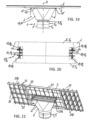
- the rotary bearing rollers 10 comprise, depending on the requirements and application, first rotary bearing rollers 10 1 projecting axially upwards on the outside of the column casing, as in the examples of Fig. 1 to 10 and 19 to 23 , or in the lower area of the support structure 6 and/or axially downward projecting second pivot bearing rollers 10 2 on the column shell outside, as in the example of Fig. 19 to 23 , or in the lower area of the support structure 6 and/or radially outwardly projecting third pivot bearing rollers 10 3 on the column shell outside, as in the example of Fig. 19 to 23 , or in the lower area of the support structure 6 and/or radially inwardly projecting fourth pivot bearing rollers on the column shell outside or, as in the example of the Fig. 11 to 14 , in the lower part of the support structure 6.
- the rotary bearing rollers 10 as for the example of the Fig. 1 to 10 specified, with respect to the axis of rotation D of the support structure 6, radial rotary bearing roller axes 10D.
- the rotary bearing ring 11 runs with its underside as a running surface horizontally on the rotary bearing rollers 10.
- the rotary bearing rollers 10 can thus absorb forces in the vertical direction.
- the rotary bearing ring 11 can also be designed as a gear ring and take over the function of the gear ring 19.
- the rotary bearing rollers 10 are attached to the outside of the column casing of the base body 5, and the rotary bearing ring 11 is attached to the lower area of the support structure 6.
- the rotary bearing rollers 10 in this example comprise the first, second and third rotary bearing rollers 10 1 , 10 2 , 10 3 , which are arranged on the outside of the column casing, projecting upwards or downwards or radially outwards.
- the rotary bearing ring 11 is formed as a profile carrier with an H-shaped cross section, as can be seen in particular from Fig. 20 visible, and attached to the underside of the support structure 6.
- an underside of this rotary bearing ring 11 functions as a support/running surface for the axially upwardly projecting, first rotary bearing rollers 10 1 , an upper side of the rotary bearing ring 11 as a support/running surface for the axially downwardly projecting, second rotary bearing rollers 10 2 and an inner side of the connecting web of the rotary bearing ring 11 between the upper side and the underside as a support/running surface for the radially outwardly projecting, third rotary bearing rollers 10 3 .
- the support structure 6, as in the examples shown, comprises a support frame 12 and a support structure 13.
- the support frame 3 is pivotally connected to the support frame 12 about the horizontal pivot axis S.
- the support structure 13 is connected to the support frame 12 at an upper side and is supported with an underside on the column casing outside of the base body 5.
- the optional upper pivot bearing unit 8 1 can be arranged on an underside of the support frame 12 and the lower pivot bearing unit 8 2 on an underside of the support structure 13.
- the support structure 13 tapers downwards in a vertical direction and thus forms an aesthetically pleasing transition between the wider support frame 12 or the wider functional unit 4 and the narrower base body 5 in comparison, which is favorable for the desired support function.
- forces and moments acting on the functional unit 4 are effectively transferred to the base body 5 by the support structure 6.
- the support frame 13 as in the embodiments of the Fig. 1 to 10 and 19 to 23 , several, in the examples shown four, support struts 14, which end at the top of the support frame with a corner profile, in this case specifically an L-profile, and at the bottom of the support frame with a circular arc profile.
- the corner profile on the top of the support frame enables the support struts 14 to be advantageously attached to the rectangular support frame 12.
- the support struts 14 are made of profiled sheets, which continuously transfer the circular arc profile on the bottom of the support frame into the corner profile on the top of the support frame.
- the support struts 14 end in a quarter-circle profile, so that in the assembled state, as in Fig.7 can be seen, together form a complete, continuous circular arc profile.
- the support struts 14 are attached to each other and to the pivot bearing ring 11, e.g. by means of screw or welded connections.
- the support struts 14 of the support frame 13 are designed as rods which extend from the corner points of the support frame 12, which is rectangular in the example shown, to the outer surface of the column casing of the Base body 5.
- the support struts 14 are connected to the pivot bearing ring 11.
- the support structure 6 according to the embodiments of the Fig. 1 to 10 and 19 to 23 and the support structure 6 according to the embodiment of the Fig. 11 to 14 can be used freely combined or interchangeable, e.g. the support structure 6 in a mounting system with the base body 5 according to the embodiment of the Fig. 11 and 12 or the base body 5 according to the embodiment of the Fig. 13 and 14 and the support structure 6 in a mounting system with the base body 5 according to the embodiment of the Fig. 1 to 10 .
- the support frame 12 has a flat frame structure and the support frame 3 is hinged by a pivot bearing 20 to an edge side of the frame structure of the support frame 12.
- the support frame 3 is hinged by a pivot bearing 20 to an edge side of the frame structure of the support frame 12.
- the Fig. 1 to 10 includes the pivot bearing 20, as shown in the Fig.4 , 5 and 9 to see two joints or hinges 26, which are formed by interlocking hinge tabs 25, which protrude from the support frame 3 and the support frame 12 and are connected, for example, by means of pins or screws.
- the support frame 3 has the hinge tabs 25 in a central region of the supports forming the support frame 3, as can be seen in particular in Fig.4 As a result, the torque required to pivot the support frame 3 and the functional unit 4 held thereon is lower than with a more peripheral linkage.
- a balancing weight can optionally be held on the edge of the support frame 3, which runs parallel to and closer to the pivot axis S. If the weight is selected appropriately, the torque required to pivot the support frame 3 and the functional unit 4 is very small or negligible.
- the support frame 3 can be provided with wind deflectors, e.g. spoilers with a wing profile, to facilitate or support pivoting in windy conditions.
- the maximum possible swivel range of the support frame 3 is limited on the one hand by the flat contact of the support frame 3 against the support frame 12, as for example in the Fig. 2 , 9 , 11 and 13 shown, and on the other hand by the support frame 3 or the functional unit 4 being placed with the edge side, which inclines towards the ground when the support frame 3 is pivoted, against the support structure 6 or the base body 5.
- the mounting system has at least one, in the examples shown two pivot drives 15 for pivoting the support frame 3 about the horizontal pivot axis S.
- the pivot drive 15 is a linear drive with a rod guide 15F as a first drive element and a drive rod 15S that moves linearly relative to the rod guide 15F as a second drive element.
- One drive element is held on the support structure 6 and the other drive element on the support frame 3.
- the drive rod 15S can, as in the examples shown, be designed as a rack, in whose teeth a gear wheel driven by the rod guide 15F engages.
- the drive rod 15S is pivotally connected to the support frame 3 and is pivotally guided in the rod guide 15F.
- the rod guide 15F is held on the side of the support frame 12 which is opposite the hinges 26 forming the pivot bearing 20, as can be seen in particular in the Fig.1 and 17 to see.
- the base body 5 tapers upwards in a vertical direction.
- the base body 5 can taper continuously, in particular linearly, upwards, as in the Fig. 1 to 10 shown embodiment, or stepwise, as in the Fig. 12 and in the Fig. 13 and 14 shown two-stage embodiments.
- the base body 5 is formed from a concrete or stone material and/or formed as a hollow base body and filled with a bulk material and/or a filling liquid and/or an energy storage unit as filling material.
- the energy storage unit can be used, for example, to supply the rotary drive 9 and the swivel drive 15 with electrical energy.
- the base body 5 comprises, as in the examples of Fig. 1 to 10 and 19 to 23 , several, eg two or three, columnar base parts 5 1 , 5 2 , 5 3 arranged vertically on top of each other.
- an uppermost base part 5 1 is connected to a lowermost base part 5 2 by tensile force-absorbing connectors 16.
- the base body 5 has two base parts 5 1 , 5 2 , of which the lower base part 5 2 has a hollow cylindrical shape and the upper base part 5 1 has a hollow truncated cone shape.
- the upper base part 5 1 has an annular shoulder at its lower end and the lower base part 5 2 has a complementary annular shoulder at its upper end.
- the two base parts 5 1 , 5 2 can be aligned coaxially by means of the annular shoulders.
- the annular shoulders prevent the base parts 5 1 , 5 2 from slipping horizontally against one another.
- the base body 5 is solid and has three or more disc-shaped base parts 5 1 , 5 2 , 5 3 placed on top of one another, including a base foot as the lowest base part.
- the connectors 16 as in the embodiment of the Fig. 1 to 10 shown, anchored at one end to an inner side of the lower base part 5 2 and held at the other end to an upper side of the upper base part 5 1 .
- the connectors 16 prevent an axial movement of the base parts 5 1 , 5 2 away from each other and also a mutual tilting.
- the length of the connectors 16 can be adjusted subsequently, ie when mounted on the base parts 5 1 , 5 2 , and thus the base parts 5 1 , 5 2 can be subjected to a tensile force by shortening the connectors 16, which function as tie rods, in the direction towards each other.
- the connectors 16 can have, for example, cables or rigid struts.
- the base body 5 consists of two hollow-cylindrical base parts 5 1 , 5 2 , which are arranged on top of and inside each other without being additionally connected to each other by connectors.
- the lower base part 5 1 has a larger diameter and a lower height than the upper base part 5 2 .
- the upper base part 5 1 is coaxial with the lower base part 5 2 and its underside fits precisely into a circular recess 21 in the underside of the lower base part 5 2 . This prevents the upper base part 5 1 from slipping relative to the lower base part 5 2 .
- both base parts 5 1 , 5 2 can be designed as openings 23 1 , 23 2 through which the hollow base body 5 can be filled with the filling material.
- the two base parts 5 1 , 5 2 can have cavities that are separate from one another or connected to one another.
- the opening 23 2 of the lower base part 5 2 can preferably be covered with an annular base cover 22, with a recess in the middle of the base cover 22 allowing the upper base part 5 1 to be passed through.
- the upper base part 5 1 is passed through the recess in the base cover 22 and the base cover 22 is arranged to cover the upper end face of the lower base part 5 2.
- the base cover 22 can also prevent the upper base part 5 1 from slipping or tipping relative to the lower base part 5 2 .
- the base body 5 consists of a hollow cylindrical column part 27 and a foot part 28, e.g. in the form of a circular disk, which projects radially outwards from the underside of the column part 27 and on which at least one ballast element 29 is arranged.
- the column part 27 is shaped like a hollow cylinder and the base part 28 protrudes in a circular ring from the underside of the column part 27.
- several quarter-circle-shaped ballast elements 29 are stacked on the base part 28 in several layers, with four ballast elements 29 surrounding the column part 27 in a ring.
- the ballast elements 29 are preferably connected to one another so that they cannot slip in their position or fall off the stack of ballast elements 29 or the base part 28.
- the upper end face of the column part 27 is designed as an opening 23 through which the hollow base body 5 can optionally be filled, and the support structure 6 is held on this end face.
- the ballast elements 29 can be solid or alternatively designed as fillable hollow bodies.
- the column part 27 protrudes, as in Fig. 13 shown, with an upper section adjacent to the front side in the vertical direction upwards beyond the stack of ballast elements 29 and the support structure 6 is supported on the outside of the column casing in the region of the protruding section on the base body 5. Because the ballast elements 29 arranged in a ring around the column part 27 have a larger diameter than the column part 27 and the upper section of the column part 27 protrudes beyond the ballast elements 29, in this case the base 1 tapers in two steps in the vertical direction upwards.
- the column part 27 has a prismatic, e.g. square, cross-sectional area and/or the ballast elements 29 are formed as closed ring parts, e.g. with a central, prismatic or circular recess, so that each ballast element 29 individually completely surrounds the column part 27 on the circumference.
- the ballast elements 29 are formed as closed ring parts, e.g. with a central, prismatic or circular recess, so that each ballast element 29 individually completely surrounds the column part 27 on the circumference.
- the base body 5 is formed solely by the ballast elements 29, ie without the column part 27.
- the ballast elements 29 can be formed as part-circular or fully circular elements, e.g. as hollow or solid disc bodies. The latter corresponds to the mentioned embodiment of the base body 5 in the example of Fig. 19 to 23 .
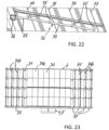
- the mounting system for mounting the functional unit 4 is set up in a special implementation in which the functional unit 4, as in the embodiment of the Figures 19 to 23 shown, comprises a frame 30 and a plurality of plate-shaped functional modules 31 arranged on the frame 30, at least some of which can be moved on the frame 30 between a use position 31a and a position tilted relative to the use position. Wind pressure relief position 31b are held pivotably.
- This functional unit 4 can in particular be a photovoltaic module with a plurality of individual modules arranged, for example, in a row or a two-dimensional field.
- the mounting system has a swivel mechanism 32 for coupled swiveling of those functional modules 31 that are held pivotably on the frame 30 of the functional unit 4.
- the swivel mechanism 32 has a drive rod 33 and a coupling rod 34 coupled to it, as well as linkage levers 35 leading from the coupling rod 34 to the individual functional modules 31 and attached to them.
- the drive rod 33 is coupled to a swivel control 36, shown only schematically, which, depending on the requirement and application, contains a motor drive and/or a brake unit and/or a coupling unit, each in a conventional design known per se. With this swivel mechanism 32, the relevant functional modules 31 can be swiveled about a respective swivel axis 37.
- the Fig. 21 and 23 show the pivotable functional modules 31, which in this example are located on the two side areas of the rectangular functional unit 4, in the wind pressure relief position 31b.
- the central functional modules 31 are permanently installed in the use position 31a, in which they lie with their usable surface parallel to the plane of the frame 30 and with which they are aligned, for example, towards the sun.
- the pivotable lateral functional modules 31 can be pivoted back from the wind pressure relief position 31b shown into this use position 31a by the pivot mechanism 32.
- the pivoting of the functional modules 31 can be done manually or by motor using a drive motor, which in this case is included in the pivot control 36.
- the pivoted functional modules 31 are inclined to the plane of the frame 30, preferably at an angle of more than 45° and preferably up to 90°.
- a wind sensor or wind pressure sensor of a type known per se can be provided in order to detect the wind pressure load on the functional unit 4 and thus on the support system supporting it and to control the pivoting of the pivotable functional modules 31 depending thereon.
- the invention provides a mounting system for a functional unit that can be set up with very little effort and can also be dismantled again if necessary, and is very stable while at the same time being designed in an aesthetically pleasing manner.
- the mounting system enables these areas to continue to be used for agricultural purposes to the greatest possible extent, despite the mounting system(s) installed.
Landscapes
- Engineering & Computer Science (AREA)
- Life Sciences & Earth Sciences (AREA)
- Sustainable Development (AREA)
- Physics & Mathematics (AREA)
- Sustainable Energy (AREA)
- Thermal Sciences (AREA)
- Chemical & Material Sciences (AREA)
- Combustion & Propulsion (AREA)
- Mechanical Engineering (AREA)
- General Engineering & Computer Science (AREA)
- Photovoltaic Devices (AREA)
Applications Claiming Priority (1)
| Application Number | Priority Date | Filing Date | Title |
|---|---|---|---|
| DE102023106674.9A DE102023106674A1 (de) | 2022-03-17 | 2023-03-16 | Aufständerungssystem |
Publications (1)
| Publication Number | Publication Date |
|---|---|
| EP4436037A1 true EP4436037A1 (fr) | 2024-09-25 |
Family
ID=90366069
Family Applications (1)
| Application Number | Title | Priority Date | Filing Date |
|---|---|---|---|
| EP24163850.1A Pending EP4436037A1 (fr) | 2023-03-16 | 2024-03-15 | Système de support |
Country Status (1)
| Country | Link |
|---|---|
| EP (1) | EP4436037A1 (fr) |
Citations (9)
| Publication number | Priority date | Publication date | Assignee | Title |
|---|---|---|---|---|
| DE2935071A1 (de) * | 1979-08-30 | 1981-03-12 | Hilmar 7636 Ringsheim Weber | Halterung fuer sonnenkollektoren. |
| DE4208255C2 (fr) | 1992-03-14 | 1994-01-27 | Zentrum Fuer Sonnenenergie- Und Wasserstoff-Forschung Stuttgart Und Ulm, 7000 Stuttgart, De | |
| EP1075629B1 (fr) | 1998-04-30 | 2002-01-02 | Zentrum Für Sonnenenergie- und Wasserstoff-Forschung Baden-Württemberg | Dispositif thermohydraulique de poursuite du soleil |
| DE10192244B4 (de) | 2000-05-31 | 2005-05-25 | Peter Swemers | Nachführvorrichtung |
| US20060054162A1 (en) * | 2004-09-03 | 2006-03-16 | Romeo Manuel L | Solar tracker |
| WO2008155652A2 (fr) * | 2007-06-19 | 2008-12-24 | Enermill Energie Rinnovabili S.R.L. | Panneau de module solaire orientable |
| EP2015369B1 (fr) * | 2007-06-06 | 2013-02-27 | IDEEMATEC Deutschland GmbH | Structure de support destinée à soutenir des panneaux solaires plats |
| DE102012021697A1 (de) | 2012-10-30 | 2014-02-13 | Friedrich Grimm | Tragsystem für die Stabilisierung von mindestens einem Mast |
| US20200403560A1 (en) * | 2018-02-16 | 2020-12-24 | Xizan Energy Efficiency S.L. | Portable system of photovoltaic panels with biaxial solar tracking structure and folding system for its transport and storage |
-
2024
- 2024-03-15 EP EP24163850.1A patent/EP4436037A1/fr active Pending
Patent Citations (9)
| Publication number | Priority date | Publication date | Assignee | Title |
|---|---|---|---|---|
| DE2935071A1 (de) * | 1979-08-30 | 1981-03-12 | Hilmar 7636 Ringsheim Weber | Halterung fuer sonnenkollektoren. |
| DE4208255C2 (fr) | 1992-03-14 | 1994-01-27 | Zentrum Fuer Sonnenenergie- Und Wasserstoff-Forschung Stuttgart Und Ulm, 7000 Stuttgart, De | |
| EP1075629B1 (fr) | 1998-04-30 | 2002-01-02 | Zentrum Für Sonnenenergie- und Wasserstoff-Forschung Baden-Württemberg | Dispositif thermohydraulique de poursuite du soleil |
| DE10192244B4 (de) | 2000-05-31 | 2005-05-25 | Peter Swemers | Nachführvorrichtung |
| US20060054162A1 (en) * | 2004-09-03 | 2006-03-16 | Romeo Manuel L | Solar tracker |
| EP2015369B1 (fr) * | 2007-06-06 | 2013-02-27 | IDEEMATEC Deutschland GmbH | Structure de support destinée à soutenir des panneaux solaires plats |
| WO2008155652A2 (fr) * | 2007-06-19 | 2008-12-24 | Enermill Energie Rinnovabili S.R.L. | Panneau de module solaire orientable |
| DE102012021697A1 (de) | 2012-10-30 | 2014-02-13 | Friedrich Grimm | Tragsystem für die Stabilisierung von mindestens einem Mast |
| US20200403560A1 (en) * | 2018-02-16 | 2020-12-24 | Xizan Energy Efficiency S.L. | Portable system of photovoltaic panels with biaxial solar tracking structure and folding system for its transport and storage |
Similar Documents
| Publication | Publication Date | Title |
|---|---|---|
| EP2926063B1 (fr) | Dispositif d'asservissement équipé d'une structure de réception déplaçable sur un ou plusieurs axes et destinée au montage d'un ou plusieurs éléments sensibles aux ondes électromagnétiques et présentant une direction de rayonnement préférentielle | |
| EP2737143B1 (fr) | Dispositif d'ancrage de superstructures dans le sol | |
| EP2707322B1 (fr) | Grue à tour pivotante | |
| EP2885587B1 (fr) | Construction porteuse pour modules solaire | |
| DE102007041199B4 (de) | Solareinrichtung | |
| WO2012152344A2 (fr) | Dispositif d'orientation et/ou suiveur pour capteurs solaires | |
| DE202007012149U1 (de) | Solareinrichtung | |
| DE202008003472U1 (de) | Anordnung aus wenigstens einem Sonnenkollektor und einem Bodenfundament | |
| EP1760031B1 (fr) | Châssis inférieur de grue optimisé pour transport | |
| EP4038274B1 (fr) | Installation photovoltaïque pour éoliennes en tant que système de génération de courant et également en tant qu'une installation autonome sans éolienne ainsi que son procédé de fonctionnement | |
| DE102006022982A1 (de) | Vorrichtung zur Montierung wenigstens eines Solarmoduls | |
| EP2741027A2 (fr) | Dispositif de support pour panneaux solaires | |
| DE69919987T2 (de) | Spannkabelzelt mit mehreren spitzen | |
| EP4436037A1 (fr) | Système de support | |
| DE102005046874A1 (de) | Vorrichtung zur Aufnahme und Nachführung von Solarkollektormodulen | |
| DE102010003148A1 (de) | Überdachungseinrichtung für Parkplätze und Parkplatz für Fahrzeuge | |
| EP3224417A1 (fr) | Élément de barrière transportable pour barrière destinée à contenir une foule | |
| WO2010124710A2 (fr) | Installation photovoltaïque | |
| DE102023106674A1 (de) | Aufständerungssystem | |
| EP4186159A1 (fr) | Structure de support destinée à supporter des modules solaires et des éléments de plafond | |
| DE102012007743A1 (de) | Photovoltaikeinheit | |
| DE202010004092U1 (de) | Überdachungseinrichtung für Parkplätze und Parkplatz für Fahrzeuge | |
| DE102009022876A1 (de) | Nachführeinheit sowie Sonnenkollektor- oder Photovoltaikeinheit | |
| EP1475493A2 (fr) | Ajustement en hauteur de plateau de podium | |
| AT512570B1 (de) | Geländer und begehbares Dach |
Legal Events
| Date | Code | Title | Description |
|---|---|---|---|
| PUAI | Public reference made under article 153(3) epc to a published international application that has entered the european phase |
Free format text: ORIGINAL CODE: 0009012 |
|
| STAA | Information on the status of an ep patent application or granted ep patent |
Free format text: STATUS: THE APPLICATION HAS BEEN PUBLISHED |
|
| AK | Designated contracting states |
Kind code of ref document: A1 Designated state(s): AL AT BE BG CH CY CZ DE DK EE ES FI FR GB GR HR HU IE IS IT LI LT LU LV MC ME MK MT NL NO PL PT RO RS SE SI SK SM TR |
|
| STAA | Information on the status of an ep patent application or granted ep patent |
Free format text: STATUS: REQUEST FOR EXAMINATION WAS MADE |
|
| 17P | Request for examination filed |
Effective date: 20250325 |