EP4436170A2 - Dispositif de codage vidéo, dispositif de décodage vidéo, procédé de codage vidéo, procédé de décodage vidéo et programme - Google Patents
Dispositif de codage vidéo, dispositif de décodage vidéo, procédé de codage vidéo, procédé de décodage vidéo et programme Download PDFInfo
- Publication number
- EP4436170A2 EP4436170A2 EP24187965.9A EP24187965A EP4436170A2 EP 4436170 A2 EP4436170 A2 EP 4436170A2 EP 24187965 A EP24187965 A EP 24187965A EP 4436170 A2 EP4436170 A2 EP 4436170A2
- Authority
- EP
- European Patent Office
- Prior art keywords
- quantization
- color space
- offset
- chroma
- prediction error
- Prior art date
- Legal status (The legal status is an assumption and is not a legal conclusion. Google has not performed a legal analysis and makes no representation as to the accuracy of the status listed.)
- Pending
Links
Images





Classifications
-
- H—ELECTRICITY
- H04—ELECTRIC COMMUNICATION TECHNIQUE
- H04N—PICTORIAL COMMUNICATION, e.g. TELEVISION
- H04N19/00—Methods or arrangements for coding, decoding, compressing or decompressing digital video signals
- H04N19/10—Methods or arrangements for coding, decoding, compressing or decompressing digital video signals using adaptive coding
- H04N19/102—Methods or arrangements for coding, decoding, compressing or decompressing digital video signals using adaptive coding characterised by the element, parameter or selection affected or controlled by the adaptive coding
- H04N19/124—Quantisation
- H04N19/126—Details of normalisation or weighting functions, e.g. normalisation matrices or variable uniform quantisers
-
- H—ELECTRICITY
- H04—ELECTRIC COMMUNICATION TECHNIQUE
- H04N—PICTORIAL COMMUNICATION, e.g. TELEVISION
- H04N19/00—Methods or arrangements for coding, decoding, compressing or decompressing digital video signals
- H04N19/10—Methods or arrangements for coding, decoding, compressing or decompressing digital video signals using adaptive coding
- H04N19/134—Methods or arrangements for coding, decoding, compressing or decompressing digital video signals using adaptive coding characterised by the element, parameter or criterion affecting or controlling the adaptive coding
- H04N19/136—Incoming video signal characteristics or properties
-
- H—ELECTRICITY
- H04—ELECTRIC COMMUNICATION TECHNIQUE
- H04N—PICTORIAL COMMUNICATION, e.g. TELEVISION
- H04N19/00—Methods or arrangements for coding, decoding, compressing or decompressing digital video signals
- H04N19/10—Methods or arrangements for coding, decoding, compressing or decompressing digital video signals using adaptive coding
- H04N19/169—Methods or arrangements for coding, decoding, compressing or decompressing digital video signals using adaptive coding characterised by the coding unit, i.e. the structural portion or semantic portion of the video signal being the object or the subject of the adaptive coding
- H04N19/17—Methods or arrangements for coding, decoding, compressing or decompressing digital video signals using adaptive coding characterised by the coding unit, i.e. the structural portion or semantic portion of the video signal being the object or the subject of the adaptive coding the unit being an image region, e.g. an object
- H04N19/176—Methods or arrangements for coding, decoding, compressing or decompressing digital video signals using adaptive coding characterised by the coding unit, i.e. the structural portion or semantic portion of the video signal being the object or the subject of the adaptive coding the unit being an image region, e.g. an object the region being a block, e.g. a macroblock
-
- H—ELECTRICITY
- H04—ELECTRIC COMMUNICATION TECHNIQUE
- H04N—PICTORIAL COMMUNICATION, e.g. TELEVISION
- H04N19/00—Methods or arrangements for coding, decoding, compressing or decompressing digital video signals
- H04N19/10—Methods or arrangements for coding, decoding, compressing or decompressing digital video signals using adaptive coding
- H04N19/169—Methods or arrangements for coding, decoding, compressing or decompressing digital video signals using adaptive coding characterised by the coding unit, i.e. the structural portion or semantic portion of the video signal being the object or the subject of the adaptive coding
- H04N19/186—Methods or arrangements for coding, decoding, compressing or decompressing digital video signals using adaptive coding characterised by the coding unit, i.e. the structural portion or semantic portion of the video signal being the object or the subject of the adaptive coding the unit being a colour or a chrominance component
-
- H—ELECTRICITY
- H04—ELECTRIC COMMUNICATION TECHNIQUE
- H04N—PICTORIAL COMMUNICATION, e.g. TELEVISION
- H04N19/00—Methods or arrangements for coding, decoding, compressing or decompressing digital video signals
- H04N19/70—Methods or arrangements for coding, decoding, compressing or decompressing digital video signals characterised by syntax aspects related to video coding, e.g. related to compression standards
Definitions
- each frame of a digitized image is divided into coding tree units (CTUs) and the respective CTUs are coded in the order of raster scan.
- the CTU is divided into coding units (CUs) in a quad-tree structure and then coded.
- Each CU is divided into prediction units (PUs) and predicted.
- PUs prediction units
- a prediction error of each CU is divided into transform units (TUs) in a quad-tree structure and then frequency-transformed.
- the CU is a coding unit for an intra prediction or inter-frame prediction.
- the intra prediction is prediction for generating a prediction signal from a reconstructed image of a frame to be encoded.
- 33 types of angular intra prediction and the like are defined.
- angular intra prediction a reconstructed pixel around a block to be encoded is extrapolated in any of 33 directions depicted in Fig. 14 , to generate an intra prediction signal.
- DC prediction In addition to angular intra prediction, DC prediction and planar prediction are specified as intra prediction.
- DC prediction a mean value of a reference image is used as the prediction values of all pixels in a TU to be predicted.
- planar prediction a prediction image is generated by linear interpolation from pixels in a reference image.
- Inter-frame prediction is a prediction based on an image of a reconstructed frame (reference picture) different in display time from a frame to be encoded. Inter-frame prediction is also referred to as inter prediction. In inter prediction, an inter prediction signal is generated based on a reconstructed image block of a reference picture (using pixel interpolation if necessary).
- a digital color image is composed of RGB digital images.
- a digital color image is generally transformed to signals in a color space other than the RGB space to increase the compression efficiency (to decrease the data amount) when the color image is transmitted through a transmission line.
- the image signal is transformed to a signal in a color space (YCoCr space) where a combination of a luma signal (Y) and chroma signals (Cb, Cr) are composed.
- a quantization parameter (QP) for the chroma signal is generated by transforming the QP for the luma signal by using an offset value "chroma_qp_index_offset.”
- cb_qp_index_offset (a first chroma quantization offset) is applied to Cb
- cr_qp_index_offset (a second chroma quantization offset) is applied to Cr.
- the adaptive color transform in residual domain is a technique of switching a prediction error signal of an image signal of the RGB space to a signal of the YCoCr space adaptively in block units (per block).
- Fig. 17 illustrates an example that data is compressed in the YCoCr space with respect to the shaded blocks and data is compressed in the RGB space with respect to other blocks.
- a receiver restores the signal of the YCoCr space to the signal of the RGB space by using a backward color space transform matrix described below and then performs decoding processing.
- Y C b C r 1 2 1 2 0 ⁇ 2 ⁇ 1 2 ⁇ 1 R G B / 4
- R G B 1 1 ⁇ 1 1 0 1 1 ⁇ 1 ⁇ 1 Y C b C r / 4
- Patent Literature 1 describes a video coding device and a video decoding device which perform signal processing which is different according to whether an input image signal is a signal of the RGB space or a signal of the YCoCr space. Specifically, when performing a weighted prediction based on the H.264/AVC, the video coding device applies the same offset to the R, G, and B signals and to theluma signal (Y signal) and applies different offsets to the chroma signals, regarding an offset added to a prediction signal. However, Patent Literature 1 does not teach any new knowledge regarding the chroma quantization offset.
- Patent Literature 1 Japanese Patent Application Laid-Open No. 2011-151683
- a general video coding device which outputs a bitstream with each CU of each frame of a digitized image as an input image.
- a video coding device illustrated in Fig. 18 includes a switch 101, a color space transformer 102, a switch 103, a frequency transformer/quantizer 104, an inverse quantizer/inverse frequency transformer 105, a switch 106, an inverse color space transformer 107, a switch 108, a buffer 109, a predictor 110, a prediction parameter determiner 111, an entropy encoder 112, a subtractor 115, and an adder 116.
- the predictor 110 generates a prediction signal for a CU input image signal. Specifically, the predictor 110 generates a prediction signal (an intra-prediction signal) on the basis of intra prediction and generates a prediction signal (an inter-prediction signal) on the basis of inter-prediction.
- a prediction image supplied from the predictor 110 is subtracted from an image input to the video coding device at the subtractor 115 and then input to the switch 101 as a prediction error image.
- an input image signal is a signal of the RGB space.
- the video coding device has a function of an adaptive color transform in residual domain. For example, the video coding device is able to adaptively switch a prediction error signal of an image signal of the RGB space to a signal of the YCoCr space in block units (per block).
- the switch 101 When a prediction error signal of the RGB space is used, the switch 101 is set so that the prediction error image is input to the switch 103. When the prediction error signal of the YCoCr space is used, the switch 101 is set so that the prediction error image is input to the color space transformer 102. Moreover, the switch 101 sets an output destination of a prediction error image according to the control of the prediction parameter determiner 111, for example.
- the color space transformer 102 transforms the prediction error signal of the RGB space to a signal of the YCoCr space by using the aforementioned equation (1) (a forward color space transform matrix) and then outputs the signal to the switch 103.
- the switch 103 When a prediction error signal of the RGB space is used, the switch 103 outputs a prediction error signal, which has been received from the switch 101, to the frequency transformer/quantizer 104. When a prediction error signal of the YCoCr space is used, the switch 103 outputs a prediction error signal, which has been received from the color space transformer 102, to the frequency transformer/quantizer 104. Moreover, the switch 103 selects the input source of the prediction error image according to the control of the prediction parameter determiner 111, for example.
- the frequency transformer/quantizer 104 frequency-transforms the prediction error image and quantizes the frequency-transformed prediction error image (a coefficient image).
- the entropy encoder 112 performs entropy coding of a prediction parameter and of a quantization coefficient image and then outputs a bitstream
- the inverse quantizer/inverse frequency transformer 105 inverse-quantizes the quantization coefficient image. Further, the inverse quantizer/inverse frequency transformer 105 performs inverse frequency transform on the inverse-quantized coefficient image. The inverse frequency transformed reconstructed prediction error image is input to the switch 106.
- the switch 106 When the prediction error signal of the RGB space is used, the switch 106 is set so that the reconstructed prediction error image is input to the switch 108. When the prediction error signal of the YCoCr space is used, the switch 106 is set so that the reconstructed prediction error image is input to the inverse color space transformer 107. The switch 106 selects an output destination of the reconstructed prediction error image according to the control of the prediction parameter determiner 111.
- the inverse color space transformer 107 transforms a reconstructed prediction error signal of the YCoCr space to a signal of the RGB space by using the aforementioned equation (1) (a backward color space transform matrix) and then outputs the to the switch 108.
- the switch 108 selects the reconstructed prediction error signal received from the switch 106 when the prediction error signal of the RGB space is used.
- the switch 108 selects the reconstructed prediction error signal received from the inverse color space transformer 107.
- the switch 108 selects any of the reconstructed prediction error images according to the control of the prediction parameter determiner 111, for example.
- the reconstructed prediction error image received from the switch 108 is supplied with a prediction signal by the adder 116 and then supplied as a reconstructed image to the buffer 109.
- the buffer 109 stores the reconstructed image.
- the prediction parameter determiner 111 instructs the predictor 110 to decide the prediction parameter which minimizes coding cost by comparing the input image signal with the prediction signal, for example.
- the prediction parameter determiner 111 supplies the decided prediction parameter to the entropy encoder 112.
- the prediction parameter is information related to block prediction such as a prediction mode (intra prediction, inter-prediction), an intra prediction block size, an intra prediction direction, an inter-prediction block size, a motion vector, or the like.
- the prediction parameter determiner 111 further instructs to decide whether the prediction error signal of the RGB space or the prediction error signal of the YCoCr space is used for each block.
- Fig. 19 is a block diagram illustrating an example of the configuration of a general video decoding device which decodes the bitstream output from a general video coding device to acquire a decoded image. Referring to Fig. 19 , the configuration and operation of the general video decoding device will be described below.
- the video decoding device illustrated in Fig. 19 includes an entropy decoder 212, an inverse quantizer/inverse frequency transformer 205, a switch 206, an inverse color space transformer 207, a switch 208, a buffer 209, a predictor 210, and an adder 216.
- the entropy decoder 212 entropy-decodes an input bitstream.
- the entropy decoder 212 supplies a quantization coefficient image to the inverse quantizer/inverse frequency transformer 205 and supplies a prediction parameter to the predictor 210.
- the inverse quantizer/inverse frequency transformer 205 inverse-quantizes the input quantization coefficient image and outputs it as a coefficient image. Furthermore, the inverse quantizer/inverse frequency transformer 205 transforms the coefficient image in the frequency domain to an image in the space domain and outputs it as a prediction error image. The prediction error image is input to the switch 206.
- the switch 206 When the prediction error signal of the RGB space is used, the switch 206 is set so that the prediction error image is input to the switch 208. When the prediction error signal of the YCoCr space is used, the switch 206 is set so that the prediction error image is input to the inverse color space transformer 207. Moreover, the switch 206 is able to recognize whether the prediction error signal of the RGB space or the prediction error signal of the YCoCr space should be used according to signaling from the video coding device.
- the inverse color space transformer 207 transforms the prediction error signal of the YCoCr space to a signal of the RGB space by using the aforementioned equation (1) (the backward color space transform matrix) and then outputs the prediction error signal to the switch 208.
- the switch 208 selects a prediction error signal received from the switch 206.
- the switch 208 selects the prediction error signal received from the inverse color space transformer 207. The switch 208 is able to recognize whether the prediction error signal of the RGB space or the prediction error signal of the YCoCr space should be used according to signaling from the video coding device.
- the prediction error image from the switch 208 is added to a prediction signal supplied from the predictor 210 at the adder 216 and then supplied as a reconstructed image to the buffer 209.
- the buffer 209 stores the reconstructed image.
- the reconstructed image stored in the buffer 209 is output as a decoded image (decoded video).
- the buffer 209 stores images, which have been decoded in the past, as reference images.
- the predictor 210 When performing the intra prediction, the predictor 210 generates a prediction image by predicting an image to be decoded on the basis of the adjacent reconstructed images, which have been decoded in the past within the image currently under decoding.
- the predictor 210 When performing the inter-prediction, the predictor 210 generates a prediction image on the basis of reference images supplied from the buffer 209.
- a chroma quantization offset (a chroma QP offset) technique for a purpose of subjective image quality improvement.
- the chroma quantization offset technique is used to adjust a quantization parameter for each color component by signaling chroma quantization offset values for a second color component and a third color component. Specifically, this technique is able to change the quantization strength.
- the subjective image quality is able to be increased by adjusting the quantization strength for each color component by using any of the above syntaxes.
- the video coding device illustrated in Fig. 18 and the video decoding device illustrated in Fig. 19 also apply a chroma quantization offset. As illustrated in Fig. 18 , a previously determined chroma quantization offset is input to the video coding device.
- the frequency transformer/quantizer 104 increases or decreases the quantization parameter of the B component according to the first chroma quantization offset and increases or decreases the quantization parameter of the R component according to the second chroma quantization offset as illustrated in Fig. 20 when quantizing a coefficient image when the prediction error signal of the RGB space is used.
- the inverse quantizer/inverse frequency transformer 105 increases or decreases the inverse quantization parameter of the B component according to the first chroma quantization offset and increases or decreases the inverse quantization parameter of the R component according to the second chroma quantization offset.
- the frequency transformer/quantizer 104 increases or decreases the quantization parameter of the Co component according to the first chroma quantization offset and increases or decreases the quantization parameter of the Cr component according to the second chroma quantization offset as illustrated in Fig. 20 when quantizing a coefficient image.
- the inverse quantizer/inverse frequency transformer 105 increases or decreases the inverse quantization parameter of the Co component according to the first chroma quantization offset and increases or decreases the inverse quantization parameter of the Cr component according to the second chroma quantization offset.
- the inverse quantizer/inverse frequency transformer 205 operates in the same manner as the inverse quantizer/inverse frequency transformer 105 in the video coding device.
- the chroma quantization offset technique is a technique of signaling the chroma quantization offset values for the second color component and the third color component. Therefore, if the adaptive color transform in residual domain is combined with the chroma quantization offset, the block compressed in the RGB space and the block compressed in the YCoCr space share the quantization strength as illustrated in Fig. 20 . Thereby, the quantization strength cannot be set appropriately according to the color space. Thus, the subjective image quality improvement effect cannot be acquired by the chroma quantization offset technique.
- a video coding device capable of selecting, from among a plurality of color spaces, a color space of a prediction error signal in coded block units, the device including: adaptive chroma quantization offset derivation means for deriving a chroma quantization offset for each color space; and inverse quantization means for inverse-quantizing a quantization coefficient image by using the chroma quantization offset for each color space.
- a video decoding device capable of selecting, from among a plurality of color spaces, a color space of a prediction error signal in coded block units, the device including: adaptive chroma quantization offset derivation means for deriving a chroma quantization offset for each color space; and inverse quantization means for inverse-quantizing a quantization coefficient image by using the chroma quantization offset for each color space.
- a video coding method capable of selecting, from among a plurality of color spaces, a color space of a prediction error signal in coded block units, the method including: deriving a chroma quantization offset for each color space; and inverse-quantizing a quantization coefficient image by using the chroma quantization offset for each color space.
- a video decoding method capable of selecting, from among a plurality of color spaces, a color space of a prediction error signal in coded block units, the method including: deriving a chroma quantization offset for each color space; and inverse-quantizing a quantization coefficient image by using the chroma quantization offset for each color space.
- a video coding program for performing a video coding method capable of selecting, from among a plurality of color spaces, a color space of a prediction error signal in coded block units, the program causing a computer to perform: a process of deriving a chroma quantization offset for each color space; and a process of inverse-quantizing a quantization coefficient image by using the chroma quantization offset for each color space.
- a video decoding program for performing a video decoding method capable of selecting, from among a plurality of color spaces, a color space of a prediction error signal in coded block units, the program causing a computer to perform: a process of deriving a chroma quantization offset for each color space; and a process of inverse-quantizing a quantization coefficient image by using the chroma quantization offset for each color space.
- Fig. 1 is a block diagram illustrating a first exemplary embodiment of a video coding device. Referring to Fig. 1 , description will be made on the configuration of a video coding device which outputs a bitstream with each frame of a digitized video as an input image.
- the video coding device of the first exemplary embodiment includes a switch 101, a color space transformer 102, a switch 103, a frequency transformer/quantizer 104, an inverse quantizer/inverse frequency transformer 105, a switch 106, an inverse color space transformer 107, a switch 108, a buffer 109, a predictor 110, a prediction parameter determiner 111, an entropy encoder 112, a subtractor 115, and an adder 116, similarly to the general video coding device illustrated in Fig. 18 .
- the video coding device further includes an adaptive chroma quantization offset derivation unit 121 and a switch 122.
- the switch 101, the color space transformer 102, the switch 103, the frequency transformer/quantizer 104, the inverse quantizer/inverse frequency transformer 105, the switch 106, the inverse color space transformer 107, the switch 108, the buffer 109, the predictor 110, the subtractor 115, and the adder 116 operate in the same manner as those illustrated in Fig. 18 , the following mainly describes the operations of the adaptive chroma quantization offset derivation unit 121 and the switch 122 and the operations of the prediction parameter determiner 111 and the entropy encoder 112 related to the signaling of the chroma quantization offsets. Moreover, the adaptive chroma quantization offset derivation unit 121 receives an input of a chroma quantization offset for the RGB space and an input of a chroma quantization offset for the YCoCr space.
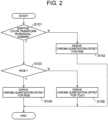
- Fig. 2 is a flowchart illustrating processing related to signaling of chroma quantization offsets.
- the video coding device signals information indicating whether the adaptive color transform in residual domain is performed or not by adaptive_color_trans_flag. Moreover, when performing the adaptive color transform in residual domain, the video coding device signals information indicating the color space of the block by cu_residual_csc_flag.
- the entropy encoder 112 transmits the chroma quantization offset for the RGB space derived by the adaptive chroma quantization offset derivation unit 121 by using the following syntax (steps S103 and S104).
- the entropy encoder 112 transmits the chroma quantization offset for the YCoCr space derived by the adaptive chroma quantization offset derivation unit 121 by using the following syntax (steps S103 and S105).
- the adaptive chroma quantization offset derivation unit 121 outputs the derived chroma quantization offsets (the first chroma quantization offset and the second chroma quantization offset) for the YCoCr space to the switch 122.
- the adaptive chroma quantization offset derivation unit 121 outputs the derived chroma quantization offsets (the first chroma quantization offset and the second chroma quantization offset) for the RGB space to the switch 122.
- the adaptive chroma quantization offset derivation unit 121 recognizes whether the compression is performed in the RGB space or in the YCoCr space according to cu_residual_csc_flag.
- the frequency transformer/quantizer 104 adjusts the quantization parameter by using the chroma quantization offset decided by the prediction parameter determiner 111.
- the prediction parameter determiner 111 stores the values of the chroma quantization offsets for the RGB space and the values of the chroma quantization offsets for the YCoCr space in advance, for example, and appropriately supplies the values of the chroma quantization offsets for the RGB space or the values of the chroma quantization offsets for the YCoCr space to the frequency transformer/quantizer 104.
- the values of the chroma quantization offsets for the RGB space and the values of the chroma quantization offsets for the YCoCr space are included in the prediction parameters supplied to the entropy encoder 112.
- the entropy encoder 112 signals the values of the chroma quantization offsets for the RGB space and the values of the chroma quantization offsets for the YCoCr space.
- the video coding device explicitly signals the chroma quantization offsets. Furthermore, the video coding device signals the values of the chroma quantization offsets.
- the operations of the video coding device other than the above operations are the same as the operations of the video coding device illustrated in Fig. 18 .
- Fig. 3 is a block diagram illustrating the configuration of a video decoding device which acquires a decoded image by decoding the bitstream output from the video coding device which signals chroma quantization offsets. Referring to Fig. 3 , the configuration of the video decoding device of the second exemplary embodiment will be described.
- the video decoding device of this exemplary embodiment includes an entropy decoder 212, an inverse quantizer/inverse frequency transformer 205, a switch 206, an inverse color space transformer 207, a switch 208, a buffer 209, a predictor 210, and an adder 216 similarly to the general video decoding device illustrated in Fig. 19 .
- the video decoding device further includes an adaptive chroma quantization offset derivation unit 221 and a switch 222.
- the inverse quantizer/inverse frequency transformer 205, the switch 206, the inverse color space transformer 207, the switch 208, the buffer 209, the predictor 210, and the adder 216 operate in the same manner as those illustrated in Fig. 19 , the following mainly describes the operations of the adaptive chroma quantization offset derivation unit 221 and the switch 222 and the operations of the entropy decoder 212 related to derivation of the chroma quantization offsets.
- Fig. 4 is a flowchart illustrating processing related to derivation of the chroma quantization offsets.
- the adaptive chroma quantization offset derivation unit 221 derives the chroma quantization offsets for the YCoCr space (step S204).
- the adaptive chroma quantization offset derivation unit 221 derives the chroma quantization offsets for the RGB space (step S203).
- the adaptive chroma quantization offset derivation unit 221 derives the chroma quantization offsets for the RGB space (the first chroma quantization offset q Pi Cb and the second chroma quantization offset q Pi Cr ) as follows.
- qPi Cb Clip3 ⁇ QpBdOffset C , 57 , Qp Y + pps_cb_qp_offset + slice_cb_qp_offset + CuQpOffset Cb
- qPi Cr Clip3 ⁇ QpBdOffset C , 57 , Qp Y + pps_cr_qp_offset + slice_cr_qp_offset + CuQpOffset Cr
- Clip3 (x, y, z) is a function of clipping an input z into the [x, y] range.
- Qp Y is a quantization parameter of a first color component
- CuQpOffset Cb is a chroma quantization offset for each block of a second color component
- CuQpOffset Cr is a chroma quantization offset for each block of a third color component.
- qPi Cb corresponds to a chroma quantization offset for the B component
- qPi Cr corresponds to a chroma quantization offset for the R component in the case of the RGB space in which the first color component is the G component, the second color component is the B component, and the third color component is the R component.
- the adaptive chroma quantization offset derivation unit 221 derives the chroma quantization offsets for the YCoCr space (the first chroma quantization offset qPi Cb and the second chroma quantization offset qPi Cr ) as described in the following equation (3).
- qPi Cb Clip3 ⁇ QpBdOffset C , 57 , Qp Y + alt_pps_cb_qp_offset + alt_slice_cb_qp_offset + CuQpOffset Cb
- qPi Cr Clip3 ⁇ QpBdOffset C , 57 , Qp Y + alt_pps_cr_qp_offset + alt_slice_cr_qp_offset + CuQpOffset Cr
- quantization parameter (Qp' Cb , Qp' Cr ) is calculated as described in the following equation (4).
- Qp ′ Cb qP Cb + QpBdOffset C
- Qp ′ Cr qP Cr + QpBdOffset C
- qP Cb Clip 3 ⁇ QpBdOffset C , 57 , Qp Y + pps _ cb _ qp _ offset + slice _ cb _ qp _ offset + CuQpOffset Cb
- qPi Cr Clip 3 ⁇ QpBdOffset C , 57 , Qp Y + pps _ cr _ qp _ offset + slice _ cr _ qp _ offset + CuQpOffset Cr
- the inverse quantizer/inverse frequency transformer 205 increases or decreases the quantization parameter according to the chroma quantization offsets from the adaptive chroma quantization offset derivation unit 221 when inverse-quantizing the input quantization coefficient image and outputting it as a coefficient image.
- Fig. 5 is an explanatory diagram illustrating an example of a syntax for transmitting alt_pps_cb_qp_offset and alt_pps_cr_qp_offset (an improvement of a syntax described in "7.3.2.3.2 Picture parameter set range extensions syntax" of Non Patent Literature 1).
- wordings written in italics indicate characteristics of this exemplary embodiment.
- Figs. 6 and 7 are explanatory diagrams illustrating examples of syntaxes for transmitting alt_slice_qp_delta_cb and alt_slice_qp_delta_cr (improvements of a syntax described in "7.3.6.1 General slice segment header syntax").
- wordings written in italics indicate characteristics of this exemplary embodiment.
- the configuration of the video coding device of this exemplary embodiment is the same as the configuration illustrated in Fig. 1 .
- the entropy encoder 112 transmits information by which the chroma quantization offsets for the RGB space are able to be identified (for example, an index specifying a data table in which chroma quantization offsets retained in the video decoding device are set or values of the chroma quantization offsets) to the video decoding device.
- the entropy encoder 112 When data is compressed in the YCoCr space, the entropy encoder 112 signals the information by which the chroma quantization offsets for the YCoCr space are able to be identified (for example, the values of the chroma quantization offsets themselves) by using the syntaxes illustrated in Fig. 5 and Figs. 6 and 7 .
- the video decoding device of this exemplary embodiment corresponds to the video coding device of the third exemplary embodiment. Note that the configuration of the video decoding device of this exemplary embodiment is the same as the configuration illustrated in Fig. 3 .
- the adaptive chroma quantization offset derivation unit 221 derives the chroma quantization offsets in the same manner as in the second exemplary embodiment.
- the adaptive chroma quantization offset derivation unit 121 operates in the same manner as the adaptive chroma quantization offset derivation unit 221.
- Fig. 8 is an explanatory diagram illustrating an example of a syntax for additionally transmitting cb_qp_offset list [i] and cr_qp_offset_list [i] for the YCoCr space (an improvement of a syntax described in "7.3.2.3.2 Picture parameter set range extensions syntax" of NPL 1).
- Fig. 8 is an explanatory diagram illustrating an example of a syntax for additionally transmitting cb_qp_offset list [i] and cr_qp_offset_list [i] for the YCoCr space (an improvement of a syntax described in "7.3.2.3.2 Picture parameter set range extensions syntax" of NPL 1).
- Fig. 8 is an explanatory diagram illustrating an example of a syntax for additionally transmitting cb_qp_offset list [i] and cr_qp_offset_list [i] for the YCoCr space (an improvement of a syntax described in "7.3.2.3.2 Picture parameter set range extensions syntax" of NPL 1).
- wordings written in italics indicate characteristics of this exemplary embodiment (specifically, the parts indicate that the size of cb_qp_offset_list/cr_qp_offset_list [the range of chroma_qp_offset_list_len_minus1] is increased according to the value of adaptive_color_trans_flag).
- the quantization offsets are able to be switched between those for the RGB space and those for the YCoCr space in block units by adjusting the value of the cu_chroma_qp_offset_idx syntax transmitted in block units according to the value of the cu_residual_csc_flag syntax.
- the configuration of the video coding device of this exemplary embodiment is the same as the configuration illustrated in Fig. 1 .
- the entropy encoder 112 transmits information by which the chroma quantization offsets for the RGB space are able to be identified (for example, a cu_chroma_qp_offset_idx syntax which is an index for specifying a data table in which chroma quantization offsets retained in the video decoding device are set) to the video decoding device.
- the chroma quantization offsets are able to be switched between those for the RGB space and those for the YCoCr space in block units on the basis of the value of the cu_chroma_qp_offset_idx syntax transmitted in block units according to the value of the cu_residual_csc _flag syntax.
- wordings written in italics correspond to the chroma quantization offsets for the YCoCr space described above in Fig. 8 .
- the video decoding device of this exemplary embodiment corresponds to the video coding device of the fifth exemplary embodiment.
- the configuration of the video decoding device of this exemplary embodiment is the same as the configuration illustrated in Fig. 3 .
- the chroma quantization offsets are read from the data table specified by the index, for example, and the adaptive chroma quantization offset derivation unit 221 calculates the chroma quantization parameter in the same manner as in the second exemplary embodiment.
- the adaptive chroma quantization offset derivation unit 121 operates in the same manner as the adaptive chroma quantization offset derivation unit 221.
- Fig. 9 is an explanatory diagram illustrating an example of a syntax for transmitting alt_cb_qp_offset_list [i] and alt_cr_qp_offset_list [i] for the YCoCr space (an improvement of a syntax described in "7.3.2.3.2 Picture parameter set range extensions syntax" described in NPL 1).
- wordings written in italics indicate characteristics of this exemplary embodiment.
- the interpretation of the value of the cu_chroma_qp_offset_idx syntax changes according to the value of the cu_residual_csc_flag syntax in comparison with the fifth exemplary embodiment as described later, and therefore the bits of the cu_chroma_qp_offset_idx syntax transmitted for each block are able to be saved.
- the configuration of the video coding device of this exemplary embodiment is the same as the configuration illustrated in Fig. 1 .
- the entropy encoder 112 transmits information by which the chroma quantization offsets for the RGB space are able to be identified (for example, an index for specifying a data table in which the chroma quantization offsets retained in the video decoding device are set) to the video decoding device.
- the entropy encoder 112 transmits information by which the chroma quantization offsets for the YCoCr space are able to be identified (for example, an index for specifying a data table in which the chroma quantization offsets retained in the video decoding device are set) to the video decoding device.
- the video decoding device of this exemplary embodiment corresponds to the video coding device of the seventh exemplary embodiment.
- the configuration of the video decoding device of this exemplary embodiment is the same as the configuration illustrated in Fig. 3 .
- the chroma quantization offsets are read from the data table specified by the index, for example, and the adaptive chroma quantization offset derivation unit 221 calculates the chroma quantization parameter in the same manner as in the second exemplary embodiment.
- the adaptive chroma quantization offset derivation unit 121 operates in the same manner as the adaptive chroma quantization offset derivation unit 221.
- cu_chroma_qp_offset_idx when present, specifies the index into the cb_qp_offset_list [ ] and cr_qp_offset_list [ ] or the alt_cb_qp_offset_list [ ] and alt_cr_qp_offset_list [ ] that is used to determine the value of CuQpOffsetCb and CuQpOffsetCr.
- the value of cu_chroma_qp_offset_idx shall be in the range of 0 to chroma_qp_offset_list_len_minus1, inclusive.
- the value of cu_chroma_qp_offset_idx is inferred to be equal to 0.
- cu_chroma_qp_offset_flag when cu_chroma_qp_offset_flag is present, the following applies:
- the video coding device explicitly signals the chroma quantization offsets in the above exemplary embodiments, the signaling of the chroma quantization offsets may be omitted though it is signaled that the color space of the prediction error signal is selected in block units. In the present description, the above is referred to as chroma quantization offsets are implicitly signaled.
- the adaptive chroma quantization offset derivation unit 221 reads out the values of the chroma quantization offsets for the RGB space previously stored in the video decoding device.
- the adaptive chroma quantization offset derivation unit 221 calculates the values of the chroma quantization offsets for the YCoCr space from the values of the previously-stored chroma quantization offsets for the RGB space.
- the adaptive chroma quantization offset derivation unit 221 is able to derive the chroma quantization offsets for the YCoCr space by using the calculation formula.
- the video decoding device implicitly derives the chroma quantization offsets.
- the adaptive chroma quantization offset derivation unit 121 operates in the same manner as the adaptive chroma quantization offset derivation unit 221.
- the video coding device implicitly signals chroma quantization offsets, the amount of data to be transmitted is able to be reduced.
- the RGB space and the YCoCr space are illustrated as two color spaces in the above exemplary embodiments, the system of the above exemplary embodiments is applicable even if one or both of the two color spaces are other color spaces.
- the first color component G, the second color component B, and the third color component R are used in the RGB space in the above exemplary embodiments (see Fig. 20 ), the way of allocating color signals to the respective color components is not limited thereto, but arbitrary color signals can be allocated to the respective color components.
- the video coding device and the video decoding device use two color spaces in the above exemplary embodiments, these devices are also allowed touse three or more color spaces.
- each of the exemplary embodiments described above may be realized by hardware, but may also be realized by a computer program.
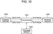
- the information processing system illustrated in Fig. 10 includes a processor 1001, a program memory 1002, a storage medium 1003 for storing video data, and a storage medium 1004 for storing a bitstream.
- the storage medium 1003 and the storage medium 1004 may be separate storage media, or storage areas included in the same storage medium.
- a magnetic storage medium such as a hard disk is available as such a storage medium.
- the program memory 1002 stores a program for realizing the functions of the blocks (except the block of the buffer) illustrated in each of Figs. 1 and 3 .
- the processor 1001 realizes the functions of the video coding device or video decoding device illustrated in Fig. 1 or Fig. 3 by executing the processes according to the program stored in the program memory 1002.
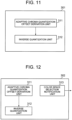
- Fig. 11 is a block diagram illustrating the main part of the video coding device.
- the video coding device 301 includes an adaptive chroma quantization offset derivation unit 311 (corresponding to the adaptive chroma quantization offset derivation unit 121 illustrated in Fig. 1 , for example) which derives chroma quantization offsets for each color space and an inverse quantization unit 312 (corresponding to the inverse quantizer/inverse frequency transformer 105 illustrated in Fig. 1 , for example) which inverse-quantizes a quantization coefficient image by using the chroma quantization offsets for each color space.
- an adaptive chroma quantization offset derivation unit 311 corresponding to the adaptive chroma quantization offset derivation unit 121 illustrated in Fig. 1 , for example
- an inverse quantization unit 312 corresponding to the inverse quantizer/inverse frequency transformer 105 illustrated in Fig. 1 , for example
- Fig. 12 is a block diagram illustrating another example of the main part of the video coding device.
- the video coding device 302 further includes a color space selection notification unit 313 (corresponding to the entropy encoder 112 illustrated in Fig. 1 , for example) which signals that the color space of a prediction error signal is to be selected in block units.
- the video coding device 302 includes a means for signaling information by which the values of the quantization offsets for each color space are able to be identified in the configuration illustrated in Fig. 12 , the chroma quantization offsets are implicitly derived in the video coding device 302.
- Fig. 13 is a block diagram illustrating still another example of the main part of the video coding device.
- the video coding device 303 further includes a quantization offset information transmission unit 314 (corresponding to the entropy encoder 112 illustrated in Fig. 1 , for example) which signals information by which the values of the chroma quantization offsets for each color space are able to be identified.
- the information by which the values of chroma quantization offsets are able to be identified is the values themselves of the chroma quantization offsets or an index for specifying the data table in which the chroma quantization offsets retained in the video decoding device are set, for example.
- Fig. 14 is a block diagram illustrating the main part of the video decoding device.
- the video decoding device 401 includes an adaptive chroma quantization offset derivation unit 411 (corresponding to the adaptive chroma quantization offset derivation unit 221 illustrated in Fig. 3 , for example) which derives chroma quantization offsets for each color space and an inverse quantization unit 412 (corresponding to the inverse quantizer/inverse frequency transformer 205 illustrated in Fig .3 , for example) which inverse-quantizes a quantization coefficient image by using the chroma quantization offsets for each color space.
- an adaptive chroma quantization offset derivation unit 411 corresponding to the adaptive chroma quantization offset derivation unit 221 illustrated in Fig. 3 , for example
- an inverse quantization unit 412 corresponding to the inverse quantizer/inverse frequency transformer 205 illustrated in Fig .3 , for example
- Fig. 15 is a block diagram illustrating another example of the main part of the video decoding device.
- the video decoding device 402 further includes a color space selection parsing unit 413 (corresponding to the entropy decoder 212 illustrated in Fig. 3 , for example) which parses a bitstream to interpret that the color space of a prediction error signal is to be selected in block units.
- a color space selection parsing unit 413 corresponding to the entropy decoder 212 illustrated in Fig. 3 , for example
- the video decoding device 402 includes a means for parsing a bitstream to interpret information by which the values of the chroma quantization offsets for each color space are able to be identified in the configuration illustrated in Fig. 15 , the video decoding device 402 implicitly derives the chroma quantization offset.
- Fig. 16 is a block diagram illustrating still another example of the main part of the video decoding device.
- the video decoding device 403 further includes a chroma quantization offset parsing unit 414 (corresponding to the entropy decoder 212 illustrated in Fig. 3 , for example) which identifies the values of the chroma quantization offsets for each color space on the basis of the information interpreted from the received bitstream.
- a chroma quantization offset parsing unit 414 corresponding to the entropy decoder 212 illustrated in Fig. 3 , for example
Landscapes
- Engineering & Computer Science (AREA)
- Multimedia (AREA)
- Signal Processing (AREA)
- Compression Or Coding Systems Of Tv Signals (AREA)
- Color Television Systems (AREA)
Applications Claiming Priority (3)
| Application Number | Priority Date | Filing Date | Title |
|---|---|---|---|
| JP2014204392 | 2014-10-03 | ||
| PCT/JP2015/004037 WO2016051643A1 (fr) | 2014-10-03 | 2015-08-12 | Dispositif de codage vidéo, dispositif de décodage vidéo, procédé de codage vidéo, procédé de décodage vidéo, et programme |
| EP15847019.5A EP3203739A4 (fr) | 2014-10-03 | 2015-08-12 | Dispositif de codage vidéo, dispositif de décodage vidéo, procédé de codage vidéo, procédé de décodage vidéo, et programme |
Related Parent Applications (1)
| Application Number | Title | Priority Date | Filing Date |
|---|---|---|---|
| EP15847019.5A Division EP3203739A4 (fr) | 2014-10-03 | 2015-08-12 | Dispositif de codage vidéo, dispositif de décodage vidéo, procédé de codage vidéo, procédé de décodage vidéo, et programme |
Publications (2)
| Publication Number | Publication Date |
|---|---|
| EP4436170A2 true EP4436170A2 (fr) | 2024-09-25 |
| EP4436170A3 EP4436170A3 (fr) | 2024-10-30 |
Family
ID=55629723
Family Applications (2)
| Application Number | Title | Priority Date | Filing Date |
|---|---|---|---|
| EP24187965.9A Pending EP4436170A3 (fr) | 2014-10-03 | 2015-08-12 | Dispositif de codage vidéo, dispositif de décodage vidéo, procédé de codage vidéo, procédé de décodage vidéo et programme |
| EP15847019.5A Ceased EP3203739A4 (fr) | 2014-10-03 | 2015-08-12 | Dispositif de codage vidéo, dispositif de décodage vidéo, procédé de codage vidéo, procédé de décodage vidéo, et programme |
Family Applications After (1)
| Application Number | Title | Priority Date | Filing Date |
|---|---|---|---|
| EP15847019.5A Ceased EP3203739A4 (fr) | 2014-10-03 | 2015-08-12 | Dispositif de codage vidéo, dispositif de décodage vidéo, procédé de codage vidéo, procédé de décodage vidéo, et programme |
Country Status (19)
| Country | Link |
|---|---|
| US (2) | US11039141B2 (fr) |
| EP (2) | EP4436170A3 (fr) |
| JP (1) | JP6540707B2 (fr) |
| KR (1) | KR101989710B1 (fr) |
| CN (3) | CN107113431B (fr) |
| AU (1) | AU2015326293B2 (fr) |
| BR (1) | BR112017006461B1 (fr) |
| CA (1) | CA2963338A1 (fr) |
| CL (1) | CL2017000781A1 (fr) |
| CO (1) | CO2017003030A2 (fr) |
| MA (1) | MA40120B1 (fr) |
| MX (1) | MX2017004088A (fr) |
| PE (1) | PE20171159A1 (fr) |
| PH (1) | PH12017500600A1 (fr) |
| RU (1) | RU2017110786A (fr) |
| SG (1) | SG11201702743WA (fr) |
| TW (1) | TW201631974A (fr) |
| WO (1) | WO2016051643A1 (fr) |
| ZA (1) | ZA201702044B (fr) |
Families Citing this family (18)
| Publication number | Priority date | Publication date | Assignee | Title |
|---|---|---|---|---|
| WO2013109838A1 (fr) * | 2012-01-20 | 2013-07-25 | Sony Corporation | Extension de paramètres de quantification de chromaticité |
| EP3205098B1 (fr) | 2014-10-06 | 2020-01-08 | Telefonaktiebolaget LM Ericsson (publ) | Codage et élaboration de paramètres de quantification |
| US10477212B2 (en) * | 2016-10-11 | 2019-11-12 | Dolby Laboratories Licensing Corporation | Adaptive chroma quantization in video coding for multiple color imaging formats |
| EP3526968A4 (fr) * | 2016-10-12 | 2020-06-03 | Telefonaktiebolaget LM Ericsson (publ) | Affinement résiduel de composantes de couleur |
| WO2019148977A1 (fr) * | 2018-02-01 | 2019-08-08 | Mediatek Inc. | Procédés et appareils de codage ou de décodage vidéo avec quantification adaptative de données vidéo |
| WO2020251278A1 (fr) * | 2019-06-11 | 2020-12-17 | 엘지전자 주식회사 | Procédé de décodage d'image basé sur des données de paramètre de quantification de chrominance, et appareil associé |
| CN114208169B (zh) * | 2019-06-11 | 2024-10-18 | Lg电子株式会社 | 用于色度分量的图像解码方法及其装置 |
| WO2020262909A1 (fr) * | 2019-06-28 | 2020-12-30 | 엘지전자 주식회사 | Procédé de décodage d'image utilisant une table de paramètres de quantification de chrominance, et dispositif exécutant le procédé |
| EP4020987A4 (fr) * | 2019-08-22 | 2023-08-23 | LG Electronics Inc. | Procédé et dispositif de décodage d'image permettant de coder des informations relatives à un décalage de paramètre de quantification de chrominance |
| CN119544989A (zh) * | 2019-10-28 | 2025-02-28 | Lg电子株式会社 | 图像编码/解码设备以及传输图像的数据的设备 |
| WO2021086024A1 (fr) * | 2019-10-28 | 2021-05-06 | 엘지전자 주식회사 | Procédé de codage/décodage d'image et appareil réalisant un traitement résiduel à l'aide d'une transformation d'espace de couleur adaptative, et procédé de transmission de flux binaire |
| HUE072798T2 (hu) * | 2019-10-28 | 2025-12-28 | Lg Electronics Inc | Eljárás kép kódolására/dekódolására színtér konverzió alkalmazásával, és eljárás bitfolyam átvitelére |
| CN120075445A (zh) | 2019-11-05 | 2025-05-30 | Lg电子株式会社 | 图像编码/解码方法和图像数据的发送方法 |
| US11336913B2 (en) | 2019-11-22 | 2022-05-17 | Apple Inc. | Reference picture re-sampling |
| KR20220100599A (ko) * | 2019-11-26 | 2022-07-15 | 주식회사 윌러스표준기술연구소 | 적응적 컬러 공간 변환을 이용하는 비디오 신호 처리 방법 및 장치 |
| JP7277354B2 (ja) * | 2019-12-26 | 2023-05-18 | Kddi株式会社 | 画像復号装置、画像復号方法及びプログラム |
| US12155824B2 (en) * | 2020-03-16 | 2024-11-26 | Interdigital Ce Patent Holdings, Sas | Signaling chroma offset presence in video coding |
| CN115002512B (zh) * | 2022-05-23 | 2023-11-28 | 北京市商汤科技开发有限公司 | 视频转码方法及装置、电子设备和存储介质 |
Citations (2)
| Publication number | Priority date | Publication date | Assignee | Title |
|---|---|---|---|---|
| JP2011151683A (ja) | 2010-01-22 | 2011-08-04 | Sony Corp | 画像処理装置および方法 |
| JP2014204392A (ja) | 2013-04-09 | 2014-10-27 | Necプラットフォームズ株式会社 | 無線中継装置、無線中継装置の制御方法、プログラム、および無線通信システム |
Family Cites Families (25)
| Publication number | Priority date | Publication date | Assignee | Title |
|---|---|---|---|---|
| EP2285119B1 (fr) * | 1997-06-09 | 2015-08-05 | Hitachi, Ltd. | Décodage d'image |
| US20050259730A1 (en) | 2004-05-18 | 2005-11-24 | Sharp Laboratories Of America, Inc. | Video coding with residual color conversion using reversible YCoCg |
| KR100723408B1 (ko) | 2004-07-22 | 2007-05-30 | 삼성전자주식회사 | 컬러영상의 변환/역변환 및 양자화/역양자화 방법 및장치와, 이를 이용한 컬러영상의 부호화/복호화 방법 및장치 |
| US7184603B2 (en) | 2004-11-15 | 2007-02-27 | Smith Micro Software, Inc. | System and method for lossless compression of digital images |
| KR101138392B1 (ko) * | 2004-12-30 | 2012-04-26 | 삼성전자주식회사 | 색차 성분의 상관관계를 이용한 컬러 영상의 부호화,복호화 방법 및 그 장치 |
| KR100763178B1 (ko) | 2005-03-04 | 2007-10-04 | 삼성전자주식회사 | 색 공간 스케일러블 비디오 코딩 및 디코딩 방법, 이를위한 장치 |
| KR101246915B1 (ko) * | 2005-04-18 | 2013-03-25 | 삼성전자주식회사 | 동영상 부호화 또는 복호화 방법 및 장치 |
| CN101356825B (zh) | 2006-01-13 | 2013-06-12 | 弗劳恩霍夫应用研究促进协会 | 使用自适应色彩空间变换的画面编码 |
| KR101568708B1 (ko) * | 2007-09-02 | 2015-11-12 | 엘지전자 주식회사 | 비디오 신호처리 방법 및 장치 |
| US8279924B2 (en) | 2008-10-03 | 2012-10-02 | Qualcomm Incorporated | Quantization parameter selections for encoding of chroma and luma video blocks |
| CN102223525B (zh) | 2010-04-13 | 2014-02-19 | 富士通株式会社 | 视频解码方法和系统 |
| US8660178B2 (en) | 2010-07-01 | 2014-02-25 | Broadcom Corporation | Method and system for multi-layer rate control for a multi-codec system |
| GB2487717B (en) | 2011-01-25 | 2017-06-21 | Advanced Risc Mach Ltd | Image encoding method |
| PH12013502456A1 (en) * | 2011-06-27 | 2014-01-20 | Sun Patent Trust | Image coding method, image decoding method, image coding apparatus, image decoding apparatus, and image coding-decoding apparatus |
| JP5936939B2 (ja) * | 2011-07-14 | 2016-06-22 | パナソニック インテレクチュアル プロパティ コーポレーション オブ アメリカPanasonic Intellectual Property Corporation of America | 画像符号化方法および画像復号化方法 |
| KR20130049526A (ko) * | 2011-11-04 | 2013-05-14 | 오수미 | 복원 블록 생성 방법 |
| WO2013109838A1 (fr) | 2012-01-20 | 2013-07-25 | Sony Corporation | Extension de paramètres de quantification de chromaticité |
| US20130321675A1 (en) | 2012-05-31 | 2013-12-05 | Apple Inc. | Raw scaler with chromatic aberration correction |
| US9414054B2 (en) | 2012-07-02 | 2016-08-09 | Microsoft Technology Licensing, Llc | Control and use of chroma quantization parameter values |
| US9591302B2 (en) * | 2012-07-02 | 2017-03-07 | Microsoft Technology Licensing, Llc | Use of chroma quantization parameter offsets in deblocking |
| MX367546B (es) * | 2012-12-18 | 2019-08-27 | Sony Corp | Dispositvo para procesamiento de imagen y método para procesamiento de imagen. |
| CN103501437B (zh) * | 2013-09-29 | 2016-06-22 | 北京航空航天大学 | 一种基于分形和h.264的高光谱图像压缩方法 |
| KR101947151B1 (ko) * | 2014-03-14 | 2019-05-10 | 브이아이디 스케일, 인크. | Rgb 비디오 코딩 향상을 위한 시스템 및 방법 |
| JP6367359B2 (ja) * | 2014-03-27 | 2018-08-01 | マイクロソフト テクノロジー ライセンシング,エルエルシー | 色空間を切り替えるときの量子化/スケーリング及び逆量子化/スケーリングの調整 |
| US10142642B2 (en) * | 2014-06-04 | 2018-11-27 | Qualcomm Incorporated | Block adaptive color-space conversion coding |
-
2015
- 2015-08-12 PE PE2017000516A patent/PE20171159A1/es unknown
- 2015-08-12 MX MX2017004088A patent/MX2017004088A/es unknown
- 2015-08-12 CN CN201580053910.9A patent/CN107113431B/zh active Active
- 2015-08-12 WO PCT/JP2015/004037 patent/WO2016051643A1/fr not_active Ceased
- 2015-08-12 MA MA40120A patent/MA40120B1/fr unknown
- 2015-08-12 BR BR112017006461-8A patent/BR112017006461B1/pt active IP Right Grant
- 2015-08-12 CN CN202011133211.4A patent/CN112261410B/zh active Active
- 2015-08-12 CA CA2963338A patent/CA2963338A1/fr not_active Abandoned
- 2015-08-12 SG SG11201702743WA patent/SG11201702743WA/en unknown
- 2015-08-12 AU AU2015326293A patent/AU2015326293B2/en active Active
- 2015-08-12 JP JP2016551481A patent/JP6540707B2/ja active Active
- 2015-08-12 EP EP24187965.9A patent/EP4436170A3/fr active Pending
- 2015-08-12 RU RU2017110786A patent/RU2017110786A/ru unknown
- 2015-08-12 CN CN202011133253.8A patent/CN112261411B/zh active Active
- 2015-08-12 KR KR1020177009057A patent/KR101989710B1/ko active Active
- 2015-08-12 US US15/516,223 patent/US11039141B2/en active Active
- 2015-08-12 EP EP15847019.5A patent/EP3203739A4/fr not_active Ceased
- 2015-10-01 TW TW104132320A patent/TW201631974A/zh unknown
-
2017
- 2017-03-23 ZA ZA2017/02044A patent/ZA201702044B/en unknown
- 2017-03-29 CO CONC2017/0003030A patent/CO2017003030A2/es unknown
- 2017-03-31 CL CL2017000781A patent/CL2017000781A1/es unknown
- 2017-03-31 PH PH12017500600A patent/PH12017500600A1/en unknown
-
2021
- 2021-05-10 US US17/316,431 patent/US11575900B2/en active Active
Patent Citations (2)
| Publication number | Priority date | Publication date | Assignee | Title |
|---|---|---|---|---|
| JP2011151683A (ja) | 2010-01-22 | 2011-08-04 | Sony Corp | 画像処理装置および方法 |
| JP2014204392A (ja) | 2013-04-09 | 2014-10-27 | Necプラットフォームズ株式会社 | 無線中継装置、無線中継装置の制御方法、プログラム、および無線通信システム |
Non-Patent Citations (2)
| Title |
|---|
| D. FLYNN ET AL.: "High Efficiency Video Coding (HEVC) Range Extensions text specification: Draft 7", JCTVC-Q1005, JOINT COLLABORATIVE TEAM ON VIDEO CODING (JCT-VC) OF ITU-T SG 16 WP 3 AND ISO/IEC JTC 1 / SC 29/ WG 11 17TH MEETING, 4 April 2014 (2014-04-04) |
| L. ZHANG ET AL.: "SCCE5 Test 3.2.1: In-loop color-space transform", JCTVC-R0147, JOINT COLLABORATIVE TEAM ON VIDEO CODING (JCT-VC) OF ITU -T SG 16 WP 3 AND ISO/IEC JTC 1/ SC 29/ WG 11 18TH MEETING, 9 July 2014 (2014-07-09) |
Also Published As
Similar Documents
| Publication | Publication Date | Title |
|---|---|---|
| US11575900B2 (en) | Video coding device, video decoding device, video coding method, video decoding method and program | |
| US9253483B2 (en) | Signaling of scaling list | |
| US10645399B2 (en) | Method and apparatus for encoding/decoding image | |
| US9210425B2 (en) | Signaling of temporal motion vector predictor (MVP) flag for temporal prediction | |
| US11019338B2 (en) | Methods and apparatuses of video encoding or decoding with adaptive quantization of video data | |
| US9549177B2 (en) | Evaluation of signaling of collocated reference picture for temporal prediction | |
| US9319681B2 (en) | Signaling of temporal motion vector predictor (MVP) enable flag | |
| US20170006283A1 (en) | Computationally efficient sample adaptive offset filtering during video encoding | |
| KR102594690B1 (ko) | 크로마 양자화 파라미터 데이터 기반 영상 디코딩 방법 및 그 장치 | |
| TW201626797A (zh) | 視訊編碼裝置、視訊解碼裝置、視訊編碼方法、視訊解碼方法及程式 | |
| KR102644971B1 (ko) | 크로마 양자화 파라미터 테이블을 사용하는 영상 디코딩 방법 및 그 장치 | |
| JPWO2016185651A1 (ja) | 映像符号化装置、映像復号装置、映像復号方法及びプログラム | |
| HK40111466A (en) | Video coding device, video decoding device, video coding method, video decoding method and program | |
| KR20120139608A (ko) | 비디오 인코딩 및 디코딩 방법과 이를 이용한 장치 | |
| WO2014028631A1 (fr) | Signalisation d'un indicateur de validation de prédicteur de vecteur de mouvement (mvp) temporel |
Legal Events
| Date | Code | Title | Description |
|---|---|---|---|
| PUAI | Public reference made under article 153(3) epc to a published international application that has entered the european phase |
Free format text: ORIGINAL CODE: 0009012 |
|
| STAA | Information on the status of an ep patent application or granted ep patent |
Free format text: STATUS: THE APPLICATION HAS BEEN PUBLISHED |
|
| REG | Reference to a national code |
Ref country code: DE Ref legal event code: R079 Free format text: PREVIOUS MAIN CLASS: H04N0019136000 Ipc: H04N0019126000 |
|
| AC | Divisional application: reference to earlier application |
Ref document number: 3203739 Country of ref document: EP Kind code of ref document: P |
|
| AK | Designated contracting states |
Kind code of ref document: A2 Designated state(s): AL AT BE BG CH CY CZ DE DK EE ES FI FR GB GR HR HU IE IS IT LI LT LU LV MC MK MT NL NO PL PT RO RS SE SI SK SM TR |
|
| PUAL | Search report despatched |
Free format text: ORIGINAL CODE: 0009013 |
|
| AK | Designated contracting states |
Kind code of ref document: A3 Designated state(s): AL AT BE BG CH CY CZ DE DK EE ES FI FR GB GR HR HU IE IS IT LI LT LU LV MC MK MT NL NO PL PT RO RS SE SI SK SM TR |
|
| RIC1 | Information provided on ipc code assigned before grant |
Ipc: H04N 19/136 20140101ALI20240924BHEP Ipc: H04N 19/70 20140101ALI20240924BHEP Ipc: H04N 19/176 20140101ALI20240924BHEP Ipc: H04N 19/186 20140101ALI20240924BHEP Ipc: H04N 19/126 20140101AFI20240924BHEP |
|
| REG | Reference to a national code |
Ref country code: HK Ref legal event code: DE Ref document number: 40111466 Country of ref document: HK |
|
| STAA | Information on the status of an ep patent application or granted ep patent |
Free format text: STATUS: REQUEST FOR EXAMINATION WAS MADE |
|
| 17P | Request for examination filed |
Effective date: 20250428 |