EP4437923A1 - Lave-vaisselle - Google Patents
Lave-vaisselle Download PDFInfo
- Publication number
- EP4437923A1 EP4437923A1 EP22898884.6A EP22898884A EP4437923A1 EP 4437923 A1 EP4437923 A1 EP 4437923A1 EP 22898884 A EP22898884 A EP 22898884A EP 4437923 A1 EP4437923 A1 EP 4437923A1
- Authority
- EP
- European Patent Office
- Prior art keywords
- valve
- connector
- disposed
- cartridge
- discharge
- Prior art date
- Legal status (The legal status is an assumption and is not a legal conclusion. Google has not performed a legal analysis and makes no representation as to the accuracy of the status listed.)
- Pending
Links
- 239000003599 detergent Substances 0.000 claims abstract description 124
- 238000007599 discharging Methods 0.000 claims abstract description 11
- 238000005406 washing Methods 0.000 claims description 20
- 239000000463 material Substances 0.000 claims description 16
- 238000000926 separation method Methods 0.000 claims description 8
- 229910000831 Steel Inorganic materials 0.000 claims description 5
- 239000010959 steel Substances 0.000 claims description 5
- 230000007423 decrease Effects 0.000 description 5
- 238000010586 diagram Methods 0.000 description 4
- 230000000694 effects Effects 0.000 description 4
- 239000007788 liquid Substances 0.000 description 4
- 238000000034 method Methods 0.000 description 4
- 238000003825 pressing Methods 0.000 description 4
- 238000004140 cleaning Methods 0.000 description 3
- 230000008878 coupling Effects 0.000 description 3
- 238000010168 coupling process Methods 0.000 description 3
- 238000005859 coupling reaction Methods 0.000 description 3
- 125000000391 vinyl group Chemical group [H]C([*])=C([H])[H] 0.000 description 3
- 229920002554 vinyl polymer Polymers 0.000 description 3
- -1 conditioners Substances 0.000 description 2
- 239000002274 desiccant Substances 0.000 description 2
- 230000005484 gravity Effects 0.000 description 2
- 230000005389 magnetism Effects 0.000 description 2
- 238000005192 partition Methods 0.000 description 2
- 239000000853 adhesive Substances 0.000 description 1
- 230000001070 adhesive effect Effects 0.000 description 1
- 230000003749 cleanliness Effects 0.000 description 1
- 238000011109 contamination Methods 0.000 description 1
- 239000002781 deodorant agent Substances 0.000 description 1
- 238000001035 drying Methods 0.000 description 1
- 229920001903 high density polyethylene Polymers 0.000 description 1
- 239000004700 high-density polyethylene Substances 0.000 description 1
- 238000012986 modification Methods 0.000 description 1
- 230000004048 modification Effects 0.000 description 1
- 230000001151 other effect Effects 0.000 description 1
- 230000002093 peripheral effect Effects 0.000 description 1
- 239000000843 powder Substances 0.000 description 1
- 230000001846 repelling effect Effects 0.000 description 1
Images







Classifications
-
- A—HUMAN NECESSITIES
- A47—FURNITURE; DOMESTIC ARTICLES OR APPLIANCES; COFFEE MILLS; SPICE MILLS; SUCTION CLEANERS IN GENERAL
- A47L—DOMESTIC WASHING OR CLEANING; SUCTION CLEANERS IN GENERAL
- A47L15/00—Washing or rinsing machines for crockery or tableware
- A47L15/42—Details
- A47L15/44—Devices for adding cleaning agents; Devices for dispensing cleaning agents, rinsing aids or deodorants
- A47L15/449—Metering controlling devices
-
- A—HUMAN NECESSITIES
- A47—FURNITURE; DOMESTIC ARTICLES OR APPLIANCES; COFFEE MILLS; SPICE MILLS; SUCTION CLEANERS IN GENERAL
- A47L—DOMESTIC WASHING OR CLEANING; SUCTION CLEANERS IN GENERAL
- A47L15/00—Washing or rinsing machines for crockery or tableware
- A47L15/42—Details
- A47L15/44—Devices for adding cleaning agents; Devices for dispensing cleaning agents, rinsing aids or deodorants
- A47L15/4436—Devices for adding cleaning agents; Devices for dispensing cleaning agents, rinsing aids or deodorants in the form of a detergent solution made by gradually dissolving a powder detergent cake or a solid detergent block
-
- A—HUMAN NECESSITIES
- A47—FURNITURE; DOMESTIC ARTICLES OR APPLIANCES; COFFEE MILLS; SPICE MILLS; SUCTION CLEANERS IN GENERAL
- A47L—DOMESTIC WASHING OR CLEANING; SUCTION CLEANERS IN GENERAL
- A47L15/00—Washing or rinsing machines for crockery or tableware
- A47L15/42—Details
- A47L15/44—Devices for adding cleaning agents; Devices for dispensing cleaning agents, rinsing aids or deodorants
- A47L15/4445—Detachable devices
-
- A—HUMAN NECESSITIES
- A47—FURNITURE; DOMESTIC ARTICLES OR APPLIANCES; COFFEE MILLS; SPICE MILLS; SUCTION CLEANERS IN GENERAL
- A47L—DOMESTIC WASHING OR CLEANING; SUCTION CLEANERS IN GENERAL
- A47L15/00—Washing or rinsing machines for crockery or tableware
- A47L15/42—Details
- A47L15/4251—Details of the casing
- A47L15/4257—Details of the loading door
-
- A—HUMAN NECESSITIES
- A47—FURNITURE; DOMESTIC ARTICLES OR APPLIANCES; COFFEE MILLS; SPICE MILLS; SUCTION CLEANERS IN GENERAL
- A47L—DOMESTIC WASHING OR CLEANING; SUCTION CLEANERS IN GENERAL
- A47L15/00—Washing or rinsing machines for crockery or tableware
- A47L15/42—Details
- A47L15/44—Devices for adding cleaning agents; Devices for dispensing cleaning agents, rinsing aids or deodorants
- A47L15/4463—Multi-dose dispensing arrangements
-
- A—HUMAN NECESSITIES
- A47—FURNITURE; DOMESTIC ARTICLES OR APPLIANCES; COFFEE MILLS; SPICE MILLS; SUCTION CLEANERS IN GENERAL
- A47L—DOMESTIC WASHING OR CLEANING; SUCTION CLEANERS IN GENERAL
- A47L15/00—Washing or rinsing machines for crockery or tableware
- A47L15/42—Details
- A47L15/44—Devices for adding cleaning agents; Devices for dispensing cleaning agents, rinsing aids or deodorants
- A47L15/4472—Blister packaging or refill cartridges
-
- F—MECHANICAL ENGINEERING; LIGHTING; HEATING; WEAPONS; BLASTING
- F16—ENGINEERING ELEMENTS AND UNITS; GENERAL MEASURES FOR PRODUCING AND MAINTAINING EFFECTIVE FUNCTIONING OF MACHINES OR INSTALLATIONS; THERMAL INSULATION IN GENERAL
- F16K—VALVES; TAPS; COCKS; ACTUATING-FLOATS; DEVICES FOR VENTING OR AERATING
- F16K27/00—Construction of housing; Use of materials therefor
- F16K27/02—Construction of housing; Use of materials therefor of lift valves
-
- F—MECHANICAL ENGINEERING; LIGHTING; HEATING; WEAPONS; BLASTING
- F16—ENGINEERING ELEMENTS AND UNITS; GENERAL MEASURES FOR PRODUCING AND MAINTAINING EFFECTIVE FUNCTIONING OF MACHINES OR INSTALLATIONS; THERMAL INSULATION IN GENERAL
- F16K—VALVES; TAPS; COCKS; ACTUATING-FLOATS; DEVICES FOR VENTING OR AERATING
- F16K27/00—Construction of housing; Use of materials therefor
- F16K27/02—Construction of housing; Use of materials therefor of lift valves
- F16K27/029—Electromagnetically actuated valves
-
- F—MECHANICAL ENGINEERING; LIGHTING; HEATING; WEAPONS; BLASTING
- F16—ENGINEERING ELEMENTS AND UNITS; GENERAL MEASURES FOR PRODUCING AND MAINTAINING EFFECTIVE FUNCTIONING OF MACHINES OR INSTALLATIONS; THERMAL INSULATION IN GENERAL
- F16K—VALVES; TAPS; COCKS; ACTUATING-FLOATS; DEVICES FOR VENTING OR AERATING
- F16K31/00—Actuating devices; Operating means; Releasing devices
- F16K31/02—Actuating devices; Operating means; Releasing devices electric; magnetic
- F16K31/06—Actuating devices; Operating means; Releasing devices electric; magnetic using a magnet, e.g. diaphragm valves, cutting off by means of a liquid
- F16K31/0675—Electromagnet aspects, e.g. electric supply therefor
Definitions
- the present disclosure relates to a dishwasher, and more particularly, to a dishwasher including a detergent supply device.
- Dishwashers are devices for removing dirt from dishes by washing, rinsing, and drying the dishes. For cleaning the dishes, a liquid or powder detergent is put into a dispenser located in the dishwasher.
- the input amount of detergent may vary as a user manually adds the detergent and the like.
- U.S. Patent No. 9,345,381 B2 discloses a detergent supply device inserted into a door. However, it is inconvenient to insert a cartridge into the door. Further, a method of discharging a liquid detergent from the cartridge is not specifically disclosed, such that it is difficult to solve the problem with adding a constant amount of detergent.
- Korean Laid-Open Patent Publication No. KR10-2011-0089733 discloses a dishwasher using a dehumidifying material in the form of a cartridge.
- the dishwasher has a structure in which the dehumidifying material is placed on an air flow path, causing a problem in that it is difficult to directly put the dehumidifying material into a washing space of a cabinet, and to put a fixed amount of dehumidifying material.
- a dishwasher of the present disclosure includes: a cabinet defining a washing space therein and having one open side; a door covering the one open side of the cabinet; and a detergent supply device mounted to the door and configured to supply a detergent to the washing space.
- the detergent supply device may include: a case mounted to one side of the door; a connector having one side removably mounted to the case and another side to which a cartridge for storing a detergent solution is mounted, the connector having a discharge chamber discharging the detergent solution stored in the cartridge to an outside; a valve movably mounted in the connector, and allowing the discharge chamber to communicate with the cartridge or allowing the discharge chamber to communicate with an outside of the connector, depending on arrangement; and a valve moving device disposed at one side of the case and configured to move the valve in a first direction, in which by moving the valve using a solenoid, the detergent solution in the cartridge may be discharged to the outside.
- the detergent solution discharged from the cartridge is discharged through the discharge chamber, such that a constant amount of detergent solution may be discharged.
- the connector may include a first discharge hole through which the detergent solution, discharged from the cartridge, is discharged to the discharge chamber, and a second discharge hole through which the detergent solution, stored in the discharge chamber, is discharged to the outside of the connector, wherein depending on arrangement, the valve may open and close the first discharge hole or the second discharge hole.
- the valve may move in a first direction in which the valve moving device is disposed or in a second direction opposite to the first direction, wherein when moving in the first direction, the valve may close the second discharge hole, and when moving in the second direction, the valve may close the first discharge hole, thereby selectively opening and closing the first discharge hole and the second discharge hole.
- the valve moving device may use a solenoid which, when a current is applied, generates a magnetic field to move the valve in the first direction.
- the connector may further include: a connector body connected to the cartridge, and having a first discharge hole through which the detergent solution discharged from the discharge chamber and the cartridge is discharged to the discharge chamber, and a second discharge hole through which the detergent solution stored in the discharge chamber is discharged to the outside of the connector; and a connector cover connected to the connector body and forming a space in which the valve moves into the valve moving device, thereby separating a space in which the valve moves from a space in which the solenoid is disposed. That is, the connector body, the valve, and the connector cover may be easily removed from the case.
- the valve may include: a valve body disposed inside the discharge chamber, and opening and closing the first discharge hole or the second discharge hole; and a valve mover connected to the valve body and moving the valve body by the valve moving device, wherein the valve mover may be disposed in a space formed by the connector cover, such that the valve opening and closing the discharge chamber is disposed in the connector cover which is disposed separately from the case.
- the connector cover may include a cover plate connected to the connector body, and a valve housing inserted into the valve moving device and defining a space in which the valve mover is disposed, wherein the valve housing may separate a space in which the valve moving device is disposed from a space in which the valve is disposed, thereby preventing the detergent solution, discharged through the discharge chamber, from flowing into the valve moving device or the case.
- the detergent supply device may include an elastic member having a first side that contacts the cover plate, and a second side that contacts the valve, wherein the elastic member may apply force to the valve in the second direction, such that when the valve moving device is not in operation, a position of the valve may be determined by the elastic member.
- the valve body may include an elastic member cover having a surface that contacts the second side of the elastic member, and defining a space in which the elastic member is disposed.
- the valve mover may include: an inner rod connected to the valve body: and a flinger made of a steel material steel responsive to the valve moving device, and disposed in the valve housing, such that the flinger may be moved by operation of the valve moving device, and the inner rod may move the valve body.
- the valve body may include: an outer rod formed in a front-rear direction in which the discharge chamber extends; a first cap disposed at an end of the outer rod, and opening and closing the first discharge hole; and a second cap extending in a circumferential direction of the outer rod, and opening and closing the second discharge hole, such that the first discharge hole and the second discharged hole may be opened and closed by the first cap and the second cap.
- the connector may include a discharge connector disposed between the connector body and the connector cover, and discharging the detergent solution, flowing from the discharge chamber, to the washing space of the cabinet, such that the detergent solution flowing from the discharge chamber may be discharged through the discharge connector.
- the discharge connector may have a cylindrical shape with a hollow inner portion and have a plurality of third discharge holes formed in a circumferential surface thereof, the plurality of third discharge holes being spaced apart from each other in a circumferential direction.
- the discharge connector may be disposed at a discharge end of the discharge chamber, wherein an inner diameter of the discharge connector may be smaller than an inner diameter of the discharge chamber, such that when the valve is moved by the valve moving device in a first direction, the valve may come into contact with the discharge connector to close the second discharge hole of the discharge chamber, in which the discharge connector may contact the valve to close the second discharge hole.
- the case may define a cartridge space therein in which the cartridge is disposed, the case including a connector mounting part which is disposed under the cartridge space and to which the connector is connected, wherein the valve moving device may be disposed at a rear of the case in which the connector mounting part is disposed., such that the valve is disposed inside the case, and the valve moving device may be disposed outside of the case.
- the connector mounting part may include a first wall in which at least one valve hole is formed, and a pair of second walls on which a fixing protrusion for fixing the connector is disposed, the pair of second walls extending forward from both ends of the first wall, wherein the first wall may include a cover housing extending to a rear side where the valve hole is formed, and defining a space in which the valve is disposed, such that an area in which the valve moving device is disposed may be separated from an area in which the valve is disposed.
- the connector may include a holder which is disposed on both sides thereof facing the second wall, and is fixed to the fixing protrusion, wherein the holder may surround the fixing protrusion, except a side in a direction in which the connector is inserted, such that the connector may be fixed to the case.
- the case may include: a rear wall disposed to face the door; an upper wall covering a top of the cartridge space; both sidewalls extending forward from both ends of the rear wall; and a lower wall covering a bottom of the cartridge space or the connector mounting part, wherein the lower wall may have an inclined structure that extends downward toward a front, such that the detergent solution discharged from the connector may flow along the lower wall.
- the dishwasher may further include a case door disposed on one side of the case and covering the cartridge space, wherein a separation space, through which the detergent solution discharged from the cartridge is discharged into the washing space, may be formed between a lower end of the case door and a lower end of the case, such that the detergent solution flowing along the lower wall may flow into the washing space through the separation space.
- a dishwasher according to the present disclosure has one or more of the following effects.
- the dishwasher includes a cartridge for storing a detergent solution, a connector for discharging a constant amount of the detergent solution, stored in the cartridge, to the outside, and a valve.
- the connector may include a discharge chamber to temporarily store the detergent solution or to discharge the detergent solution, and may move the valve using a solenoid. Accordingly, by adjusting the amount of detergent solution, the detergent may be added in an amount suitable for a washing method, thereby achieving the effect of improving cleaning performance of the dishwasher.
- an area in which a detergent solution is discharged, an area in which a solenoid is disposed, and an area in which a case is disposed are separated from each other, such that no contamination occurs in areas other than the connector. Accordingly, by removing and cleaning only the connector, the detergent supply device may remain clean.
- a connector includes a connector body, a valve, and a connector cover, only the connector may be removed from or mounted to the case, thereby allowing a user to easily install or remove the connector.
- a dishwasher includes a cabinet 12 forming an exterior thereof and defining a washing space, a door 10 opening and closing one open side of the cabinet 12, and a detergent supply device 100 configured to supply a detergent to the washing space.
- the detergent supply device 100 is mounted on the inside the door 10. Accordingly, the detergent and the like discharged from the detergent supply device 100 may be put into the washing space formed inside the cabinet 12.
- the detergent supply device 100 includes a case 102 mounted to the door 10 and defining a cartridge space 104 in which a cartridge 230 for storing a detergent is disposed, a case door 140 covering one open side of the case, a connector 150 having a discharge chamber 158 formed therein which temporarily stores a detergent solution, discharged from the cartridge 230 for storing the detergent solution, or which discharges the detergent solution to the outside, a valve 200 which is movably mounted in the discharge chamber 158 of the connector 150 and, depending on arrangement, allows the discharge chamber 158 and the cartridge 230 to communicate with each other or the discharge chamber 158 to communicate with the outside, and a valve moving device 130 fixedly disposed at one side of the case 102 and configured to allow the discharge chamber 158 to communicate with the outside or block the discharge chamber 158 from the outside.
- the connector 150 may include a connector body 151 (see FIG. 11A ) having the discharge chamber 158, a connector cover 180 (see FIG. 11A ) connected to the connector 150 and defining a space in which some components of the valve 200 are disposed, and a discharge connector 190 (see FIG. 11A ) disposed between the connector 150 and the connector cover 180 and discharging a detergent solution, flowing from the discharge chamber 158, into the washing space of the cabinet 12.
- the detergent solution stored in the cartridge 230 may be a concept including detergents, conditioners, deodorants, desiccants, and the like.
- the detergent solution stored in the cartridge 230 is a liquid-type detergent, and may flow downward by gravity when discharged from the cartridge 230.
- the case 102 defines a space in which the cartridge 230 and the connector 150 are disposed, and has one open side. Accordingly, referring to FIG. 4 , the cartridge 230 and the connector 150 may be disposed in the case 102 while the case door 140 is removed.
- the case door 140 may open and close the one open side of the case 102. That is, as illustrated in FIG. 3 , the case door 140 may close the one side of the case 102.
- the case door 140 is removably mounted to the case 102 to open the one open side of the case 102.
- a separation space 144 is formed between a lower portion of the case 102 and a lower portion of the case door 140.
- the detergent solution, discharged from the cartridge 230 and the connector 150, may be discharged through the separation space 144 into the washing space of the cabinet 12.
- the detergent supply device 100 includes a door louver 142 installed on the case door 140 and pressing the cartridge 230, disposed inside the case 102, toward the case 102.
- the door louver 142 is disposed on one side of the case door 140 to seal a space between the case door 140 and the case 102.
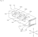
- the case 102 has the cartridge space 104 in which the cartridge 230 is disposed, and a connector mounting part 114 which is disposed under the cartridge space 104 and to which the connector 150 is connected.
- the valve moving device 130 may be disposed on the outside of the case 102 where the connector mounting part 114 is formed.
- the cartridge space 104 is greater than a space formed by the connector mounting part 114.
- the cartridge space 104 is disposed over the connector mounting part 114.
- the cartridge space 104 may have a size capable of accommodating the cartridge 230.
- the case 102 may include a rear wall 106 disposed to face the door 10, an upper wall 108 covering the top of the cartridge space 104, both sidewalls 110 extending forward from both ends of the rear wall 106, and a lower wall 112 covering the bottom of the cartridge 230 or the connector 150.
- the case 102 has an open front. Accordingly, the cartridge 230 and the connector 150 may be inserted or withdrawn through the open front of the case 102.
- a door locker 109 for fixing the position of the case door 140 may be formed at a front end of the upper wall 108.
- the lower wall 112 extends forward from a lower end of a first wall of the connector mounting part 114 which will be described later.
- the lower wall 112 may extend obliquely in a forward and downward direction from a lower end of the first wall 116. Accordingly, when the detergent solution stored in the cartridge 230 may be discharged downward through the connector 150, the detergent solution may flow forward along the lower wall 112.
- the lower wall 112 When the case door 140 is closed, the lower wall 112 may be spaced apart from the lower end of the case door 140.
- the separation space 144 spaced apart from the case door 140 may be formed at a front end of the lower wall 112. Accordingly, the detergent solution, flowing along the lower wall 112, may flow through the separation space 144 between the case door 140 and the case 102.
- the connector mounting part 114 may protrude forward from the rear wall 106 or protrude inward from the both sidewalls 110. Accordingly, the cartridge 230 may be mounted on the connector mounting part 114.
- the connector mounting part 114 may include a first wall 116 having at least one valve hole 118a, 118b, and 118c formed therein, and a pair of second walls 122 extending forward from both ends of the first wall 116 and having a fixing protrusion 124 for fixing the connector 150.
- the first wall 116 may have a plane parallel to the rear wall 106.
- the first wall 116 may be disposed to face the open front of the case 102.
- At least one valve hole 118a, 118b, and 118c may be formed in the first wall 116.
- the first wall 116 includes cover housings 120a, 120b, and 120c defining a space in which the valve 200 is disposed, and extending to a rear side where the valve holes 118a, 118b, and 118c are formed.
- the first wall 116 includes a plurality of valve holes 118a, 118b, and 118c which are horizontally spaced apart from each other.
- the first wall 16 includes a plurality of cover housings 120a, 120b, and 120c which are horizontally spaced apart from each other.
- the cover housings 120a, 120b, and 120c separate an area in which the valve 200 is disposed, from an area in which the valve moving device 130 is disposed. Accordingly, it is possible to prevent a detergent and the like, flowing through the valve 200, from entering the area in which the valve moving device 130 is disposed.
- the valve moving device 130 may use a solenoid which changes the position of the valve 200 by magnetism.
- the valve moving device 130 may include a component capable of performing the function of attracting or repelling the valve 200 in a first direction.
- the valve moving device 130 may also use a hydraulic device, e-mobility, and an elastic device.
- a structure of the valve moving device 130 using the solenoid will be described with reference to the drawings.
- the valve moving device 130 that changes the position of the valve 200 by magnetism is disposed around the cover housings 120a, 120b, and 130c. When a current is applied, the valve moving device 130 generates a magnetic field to attract the valve 200 rearward.
- the valve moving device 130 may have a shape in which a plurality of coils are wrapped around the circumference of the cover housings 120a, 120b, and 120c.
- a terminal electrically connected to the outside may be disposed at one side of the valve moving device 130.
- the detergent supply device 100 includes a solenoid cover 132 for fixing the position of the valve moving device 130 disposed around the cover housings 120a, 120b, and 120c.
- the solenoid cover 132 may cover the upper side and the rear side of the valve moving device 130.
- the solenoid cover 132 may be mounted to the case 102.
- the connector 150 may be connected to the cartridge 230 and may be mounted on one side of the case 102. Referring to FIG. 18 , the connector 150 is mounted to the connector mounting part 114 of the case 102. The connector 150 is connected to the cartridge 230 disposed over the connector 150.
- the connector 150 may include the connector body 151 having the discharge chamber 158 formed therein in which an inner flow path 152, through which a detergent solution flows, and some components of the valve 200 are disposed, the connector cover 180 connected to the connector 150 and defining a space in which some components of the valve 200 are disposed, and the discharge connector 190 disposed between the connector body 151 and the connector cover 180 and discharging a detergent solution, flowing from the discharge chamber 158, into the washing space of the cabinet 12.
- the connector body 151 includes an inlet port 162 formed in an upper portion thereof and connected to an outlet port 240 of the cartridge 230.
- the inlet port 162 is formed in the upper portion of the connector 150.
- the upper portion of the connector body 151 may be an area located at an upper end of the inner flow path 152 formed inside the connector 150.
- the upper portion of the connector 150 may include an upper surface of the connector body 151, and may also include a portion of a peripheral surface of the connector 150.
- the inlet port 162 is formed in an upper portion of a front surface of the connector 150.
- the outlet port 240 of the cartridge 230 which will be described below, is mounted in the inlet port 162.
- the inlet port 162 has a mounting recess 164 in which the outlet port 240 of the cartridge 230 is mounted.
- the inlet port 162 has an inlet 154 which is formed at an end of the mounting recess 164, and through which the detergent solution, discharged from the cartridge 230, flows into the inner flow path 152.
- a rubber 165 that seals a space between the outlet port 240 and the connector 150 may be formed in the mounting recess 164.
- the mounting recess 164 forms a space in which a port exit 248 of the outlet port 240 is inserted.
- the inlet 154 is formed in the mounting recess 164 at a position corresponding to an outlet 250 of the outlet port 240.
- the inner flow path 152 for supplying the detergent solution, introduced through the inlet 154, to the discharge chamber 158 is formed inside the connector body 151.
- a separate pin is not disposed on the connector body 151.
- a user may directly remove a hole cover disposed on the outlet port 240 of the cartridge 230, to connect the cartridge 230 to the connector 150.
- a pin 262 protruding from an inner surface of the inner flow path 152 toward the inlet 154 may be disposed on the connector body 151b.
- the pin 262 may be spaced radially inward from an inner circumferential surface of the inlet 154, and may protrude to the outside of the connector body 151 having the mounting recess 164 formed therein. Accordingly, when the cartridge 230 is mounted in the inlet port 162, a hole cover (not shown) of the outlet port 240 of the cartridge 230 may be opened.
- the inner flow path 152 forms a flow path through which the detergent solution flows downward.
- a first discharge hole 156 is formed at a lower end of the inner flow path 152 so as to communicate with the discharge chamber 158.
- the inlet 154 is disposed above the first discharge hole 156, such that the detergent solution introduced through the inlet 154 may flow to the first discharge hole 156 by gravity.
- the discharge chamber 158 forms a space for temporarily storing and discharging the detergent solution discharged from the inner flow path 152.
- the discharge chamber 158 includes a valve 200 that linearly reciprocates therein.
- the discharge chamber 158 is formed in a front-rear direction.
- the discharge chamber 158 may have a cylindrical structure with a diameter greater than a diameter 156D of the first discharge hole 156.
- the second rib 170 and the third rib 172 may be disposed to face each other. Each of the second rib 170 and the third rib 172 may be disposed perpendicular to each other with respect to the first rib 168. The second rib 170 and the third rib 172 may become closer to each other toward the first rib 168. That is, the fixing protrusion 124 may be smoothly inserted into the holder 166, and when fully inserted, a position of the fixing protrusion 124 may be fixed by the second rib 170 and the third rib 172.
- the first wall 116 may come into contact with the fixing protrusion 124 to limit rearward movement of the connector 150.
- the fixing protrusion 124 may be press-fitted between the second rib 170 and the third rib 172, such that its position may be fixed.
- the fixing protrusion 124 of the case 102 and the holder 166 of the connector 150 may be formed in different structures.
- the connector 150 may be inserted into or withdrawn from the case 102 in a vertical direction.
- the holder 166 may be opened at the bottom side, and the top, front, and rear sides thereof may surround the fixing protrusion 124.
- the holder 166 may include the first rib 168 disposed to face the fixing protrusion 124, the second rib 170 bent from one end of the first rib 168, and the third rib 172 bent from another end of the first rib 168, when the connector 150 is mounted in the case 102.
- the first rib 168 may come into contact with the fixing protrusion 124 to limit rearward movement of the connector 150.
- the second rib 170 and the third rib 172 may be disposed to face each other.
- the second rib 170 may be formed perpendicular to the first rib 168.
- the third rib 172 may be inclined with respect to the first wall 116. A distance between the second rib 170 and the third rib 172 may decrease toward the first rib 168.
- a protrusion 174 protruding toward the fixing protrusion 124, may be formed at an end of the second rib 170.
- the connector cover 180 while being coupled to the connector body 151, may be mounted in the case 102. As a portion of the connector cover 180, which accommodates some components of the valve 200, is inserted into the valve moving device 130, the area in which the valve moving device 130 is disposed and the area in which the valve 200 is disposed may be separated by the connector cover 180.
- the connector cover 180 separates a space in which the valve 200 moves from the area in which the valve moving device 130 is disposed.
- the connector cover 180 may be connected at one side to the connector and may define a space in which some components of the valve 200 are disposed.
- the connector cover 180 may define a space in which some components of the valve 200 are disposed.
- the connector cover 180 includes a cover plate 182 disposed to face the case 102 and connected to the connector 150, and a valve housing 184 inserted into the valve moving device 130 and defining a space in which the valve 200 is disposed.
- the valve housing 184 is inserted into the cover housings 120a, 120b, and 120c, and defines a space in which the valve 200 is disposed.
- the valve housing 184 may separate a space in which the valve 200 is disposed from a space in which the valve moving device 130 is disposed.
- the valve housing 184 may separate a space in which the valve 200 is disposed from a space in which the case 102 is disposed. Accordingly, an area in which the valve 200 that opens and closes the discharge chamber 158 is disposed may be separated from the case 102.
- the cover plate 182 may be connected to the connector body 151.
- the cover plate 182 may be disposed to contact the rear wall 106 of the case 102.
- An elastic member 186 which applies elastic force to the valve 200 in a direction toward the first discharge hole 156, may be disposed on the cover plate 182.
- a spring may be used as the elastic member 186.
- a first side of the elastic member 186 may contact the cover plate 182, and a second side thereof contacts the valve 200, thereby applying a force to the valve 200 in a second direction.
- the second direction may be a front direction in FIG. 11A and a direction in which the valve 200 is moved by the elastic force of the elastic member 186.
- the second direction may be an opposite direction of the first direction in which the valve 200 is moved by the valve moving device 130.
- the first direction may be a direction in which the valve moving device 130 is disposed with respect to the discharge connector 190, and may be a rear direction in FIG. 11A .
- the second direction may be a direction in which the discharge chamber 158 is disposed with respect to the discharge connector 190.
- the elastic member 186 may apply force to the valve 200 in the second direction, and the valve 200 may close the first discharge hole 156.
- the discharge connector 190 is disposed between the connector cover 180 and the connector body 151.
- the discharge connector 190 is disposed at a discharge end of the discharge chamber 158. Accordingly, when the second discharge hole 160 of the discharge chamber 158 is opened by the valve 200, a detergent solution present in the discharge chamber 158 may flow to the discharge connector 190.
- the discharge connector 190 may have a cylindrical shape with a hollow inner portion. An inner diameter 190D of the discharge connector 190 is smaller than an inner diameter 158D of the discharge chamber 158. Accordingly, when the valve 200 is moved by the valve moving device 130 in the first direction, a second cap 208 of the valve 200 comes into contact with the discharge connector 190, to close the second discharge hole 160 of the discharge chamber 158.
- a plurality of third discharge holes 192 may be circumferentially spaced apart from each other in the circumferential surface of the discharge connector 190.
- valve will be described with reference to FIGS. 9 to 11B .
- the valve 200 is disposed so as to be movable forward and rearward in the discharge chamber 158 formed in the connector 150.
- the valve 200 is movably disposed in the valve housing 184 of the connector cover 180.
- the valve 200 is movably disposed in the cover housings 120a, 120b, and 120c of the case 102.
- the valve 200 may allow the discharge chamber 158 and the cartridge 230 to communicate with each other or allow the discharge chamber 158 and the outside of the connector 150 to communicate with each other.
- the valve 200 allowing the discharge chamber 158 and the cartridge 230 to communicate with each other may include allowing the discharge chamber 158 and the cartridge 230 to directly communicate with each other, as well as allowing the discharge chamber 158 and the cartridge 230 to communicate with each other indirectly through the inner flow path 152 disposed therebetween.
- the valve 200 may open and close the first discharge hole 156 formed between the discharge chamber 158 and the inner flow path 152.
- the valve 200 may open and close the second discharge hole 160 of the discharge chamber 158.
- the valve 200 may move in the first direction in which the valve moving device 130 is disposed.
- the valve 200 may move in the second direction opposite to the first direction.
- the valve 200 includes a valve body 202 disposed in the discharge chamber 158 and opening and closing the first discharge hole 156 or the second discharge hole 160, and a valve mover 214 connected to the valve body 202 and moving the position of the valve body 202 by the valve moving device 130.
- valve body 202 may close the first discharge hole 156 or close the second discharge hole 160 of the discharge chamber 158.
- the valve body 202 includes a first cap 206 opening and closing the first discharge hole 156, and a second cap 208 opening and closing the second discharge hole 160.
- the valve body 202 includes an elastic member cover 210 defining a space in which the elastic member 186 is disposed.
- the valve body 202 includes an outer rod 205 formed in a front-rear direction in which the discharge chamber 158 extends.
- the outer rod 204 may be formed in a bar shape elongated in the front-rear direction and having a hollow inner portion.
- the outer rod 204 may define an internal space therein into which the valve mover 214 is inserted.
- An inner rod 216 of the valve mover 214 which will be described below, may be inserted into the internal space of the outer rod 204, such that the valve body 202 may be coupled to the valve mover 214.
- An inner protrusion 212 fixing the position of the inner rod 216, inserted into the outer rod 204 may be formed on an inner circumferential surface of the outer rod 204.
- the inner protrusion 212 is inserted into an inner rod groove 218 of the inner rod 216 which will be described below, thereby fixing the position of the inner rod 216 inserted into the outer rod 204.
- the first cap 206 is disposed at an end of the outer rod 204.
- a diameter 206D of the first cap 206 is greater than a diameter 156D of the first discharge hole 156.
- the second cap 208 extends in a circumferential direction of the outer rod 204.
- the second cap 208 is spaced apart form the first cap 206 in the front-rear direction.
- the second cap 208 may have a conical shape that extends radially outwardly from the circumference of the outer rod 204 and in the first direction.
- An end portion of the second cap 208 that faces the discharge connector 190 may be formed in a step shape. Accordingly, when the second cap 208 comes into contact with the discharge connector 190, the second discharge hole 160 may be closed.
- the second cap 208 may extend from the circumference of the outer rod 204 in an outward direction and in a rearward direction toward the discharge connector 190.
- a diameter 208D of an outer circumferential end of the second cap 208 is greater than a diameter 190D of an inner circumferential end of the discharge connector 190.
- the diameter 208D of the outer circumferential end of the second cap 208 is smaller than the diameter 158D of an inner circumferential surface of the discharge chamber 158.
- the elastic member cover 210 may be spaced rearward from the second cap 208.
- the elastic member cover 210 may have a bowl shape that is open in the second direction.
- the valve mover 214 is disposed in the elastic member cover 210.
- the elastic member 186 may be disposed between the elastic member cover 210 and the valve mover 214.
- the elastic member cover 210 may be radially spaced apart from the valve mover 214 disposed therein. Accordingly, the elastic member 186 may be disposed in a space spaced apart from the valve mover 214 in a radial direction of the elastic member cover 210.
- the elastic member cover 210 protrudes radially outwardly from the circumferential surface of the outer rod 204, and then is bent to extend in the first direction.
- a length L1 of the elastic member cover 210 that extends in the first direction is shorter than a length L2 of the discharge connector 190.
- the elastic member 186 is disposed to come into contact with each of the cover plate 182 of the connector cover 180 and the elastic member cover 210.
- the connector cover 180 is fixedly disposed, such that the elastic member cover 210 may be moved in the second direction by the elastic force of the elastic member 186.
- the elastic member cover 210 is disposed so as to be movable inside the discharge connector 190. Accordingly, a diameter 210D of an outer circumferential end of the elastic member cover 210 is smaller than the diameter 190D of the inner circumferential end of the discharge connector 190.
- the discharge connector 190 may guide linear movement of the elastic member cover 210.
- the valve mover 214 includes the inner rod 216 inserted into the outer rod 204 and connected to the valve body 202, and a flinger 220 connected to the inner rod 216, with a position of the flinger 220 being changed by operation of the valve moving device 130.
- the inner rod 216 is inserted into the outer rod 204.
- the inner protrusion 212 of the outer rod 204 is inserted into the inner rod groove 218 formed in the inner rod 216, thereby fixing the position of the inner rod 216 inserted into the outer rod 204.
- the flinger 220 may be connected to the inner rod 216 and may extend from the inner rod 216 in the first direction.
- the flinger 220 may be made of a material responsive to the magnetic force generated by the valve moving device 130.
- the flinger 220 is made of a steel material and may be changed in position by a magnetic force generated by the solenoid 130. That is, the flinger 220 may be moved in the first direction by the magnetic force generated when power is applied to the solenoid 130. In this case, the inner rod 216 connected to the flinger 220 may move in the first direction together with the valve body 202 connected to the inner rod 216.
- the cartridge 230 may include a cartridge body 232 accommodating a detergent solution, and an outlet port 240 which is connected to the cartridge body 232 and through which the detergent solution stored in the cartridge body 232 is discharged to the outside.
- the cartridge 230 may include a support plate 234 disposed at the bottom of the cartridge body 232 and having a fixed shape.
- the cartridge body 232 may be disposed on the support plate 234.
- the cartridge body 232 may be disposed on the support plate 234 using an adhesive and the like.
- the cartridge body 232 may be made of a vinyl material which may be easily changed in shape.
- the cartridge body 232 is changed in shape so that an internal volume thereof may decrease as the amount of the detergent solution stored therein decreases.
- the cartridge body 232 may be made of vinyl having a thickness of 0.05 mm to 0.1 mm.
- the cartridge body 232 may be made of vinyl of HDPE and PP material.
- the cartridge body 232 may be made of a flexible material. Accordingly, as the amount of the detergent solution in the cartridge body 232 decreases, the shape of the cartridge body 232 may be changed.
- the cartridge body 232 is made of a thin material, the amount of the detergent solution present in the cartridge body 232 may increase.
- the cartridge body 232 is made of a material that may be changed in shape, such that as the amount of the detergent solution stored therein is reduced, the shape of the cartridge body may be changed to a size corresponding to the reduced volume.
- the cartridge body 232 may include a partition wall 233 dividing the space in which the detergent solution is stored.
- the partition wall 233 may also be made of the same deformable material as the cartridge body 232.
- the cartridge body 232 is changed in shape in which as the amount of the detergent solution stored in the cartridge body 232 is reduced, an upper end of the cartridge body 232 is lowered.
- the shape of the cartridge body 232 may be changed by the pressure.
- the inside of the cartridge body 232 may be divided into a plurality of regions.
- the cartridge body 232 may be divided into a plurality of regions so that different liquid detergents may be stored separately.
- a discharge kit 238 includes three port bodies 242, such that the inside of the cartridge body 232 may be divided into three regions.
- detergent, conditioner, and desiccant may be stored in the divided regions of the cartridge body 232.
- a material having a fixed shape may be used as the support plate 234. Accordingly, the cartridge body 232 may be stably disposed on the support plate 234. A connection hole 236, through which the outlet port 240 passes, may be formed in the support plate 234. The port body 242 of the outlet port 240 is inserted into the connection hole 236, to be connected to the cartridge body 232 disposed on the support plate.
- the support plate 234 has an approximately rectangular plate shape and has the connection hole 236 formed on one side thereof.
- the outlet port 240 includes the port body 242 having a connection flow path 244 formed therein, the port exit 248 disposed on one side of the port body 242 and connected to the connector 150, and a port entrance 246 extending upward from the port body 242 and connected to the cartridge body 232.
- the outlet port 240 includes the plurality of port bodies 242 and a kit connection part 252 connecting the plurality of port bodies 242 to each other.
- connection flow path 244 disposed in the port body 242 may have a bent shape in some sections. Accordingly, the detergent solution stored in the cartridge body 232 dispose thereon may flow to the connector 150.
- the port exit 248 is mounted in the inlet port 162 of the connector body 151.
- the port exit 248 is inserted into the mounting recess 164 of the inlet port 162.
- the connection flow path 244 of the outlet port 240 may be connected to the inner flow path 152 of the connector 150.
- the port exit 248 is disposed below the port entrance 246.
- the outlet 250 through which the detergent solution stored in the cartridge body 232 is discharged, is formed in the port exit 248.
- the outlet 250 of the port exit 248 may be covered by the hole cover (not shown). However, the hole cover may be removed when a user connects the cartridge 230 to the connector 150, or the hole cover may be opened by the pin 262, disposed at the connector 150, when the cartridge 230 is mounted to the connector 150.
- the detergent supply device 100 may include a pusher 260 applying pressure to the cartridge body 232.
- the pusher 260 includes a pressure plate 260a applying pressure to the cartridge body 232, and a pressurizer 260b applying a force to the pressure plate 260a.
- the pressure plate 260a is disposed to come into close contact with the cartridge body 232.
- the pressurizer 260b is disposed between the case 102 and the pressure plate 260a.
- the pusher 260 may pressurize the cartridge body 232 at a constant pressure. Accordingly, when first valve holes 118a, 118b, and 118c are opened by the valve 200, the detergent solution stored in the cartridge body 232 may be supplied to the discharge chamber 15.
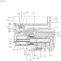
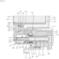
- valve 200 movement of the valve 200 by operation of the valve moving device 130 and a flow of the detergent solution will be described with reference to FIGS. 23 to 25 .
- the detergent solution stored in the cartridge body 232 does not flow to the discharge chamber 158.
- an amount of the detergent solution stored in the cartridge body 232 remains constant, such that the shape of the cartridge body 232 does not change.
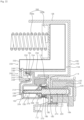
- the flinger 220 moves in the first direction. That is, the valve 200 moves in the first direction.
- the first cap 206 of the valve 200 opens the first discharge hole 156
- the second cap 208 of the valve 200 closes the second discharge hole 160.
- the detergent solution stored in the cartridge body 232 may flow downward into the discharge chamber 158.
- the detergent solution flowing through the first discharge hole 156 may be temporarily stored in the discharge chamber 158.
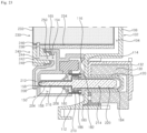
- the amount of the detergent solution filled in the discharge chamber 158 may vary depending on an operating time of the valve moving device 130.
- the valve 200 moves again in the second direction by the elastic member 186. Accordingly, the first cap 206 closes the first discharge hole 156, and the second cap 208 opens the second discharge hole 160. Accordingly, the detergent solution stored in the discharge chamber 158 flows to the discharge connector 190 through the second discharge hole 160. After flowing to the discharge connector 190, the detergent solution flows downward through the third discharge hole 192. The detergent solution flowing from the discharge connector 190 through the third discharge hole 192 flows along the lower wall 112. The detergent solution flowing along an inclined surface of the lower wall 112 may be discharged into the washing space, formed inside the cabinet 12, through the separation space 144 between the case 102 and the door 10.
Landscapes
- Engineering & Computer Science (AREA)
- General Engineering & Computer Science (AREA)
- Mechanical Engineering (AREA)
- Physics & Mathematics (AREA)
- Electromagnetism (AREA)
- Washing And Drying Of Tableware (AREA)
Applications Claiming Priority (2)
| Application Number | Priority Date | Filing Date | Title |
|---|---|---|---|
| KR1020210164507A KR20230077335A (ko) | 2021-11-25 | 2021-11-25 | 식기세척기 |
| PCT/KR2022/017016 WO2023096202A1 (fr) | 2021-11-25 | 2022-11-02 | Lave-vaisselle |
Publications (2)
| Publication Number | Publication Date |
|---|---|
| EP4437923A1 true EP4437923A1 (fr) | 2024-10-02 |
| EP4437923A4 EP4437923A4 (fr) | 2025-03-26 |
Family
ID=86539833
Family Applications (1)
| Application Number | Title | Priority Date | Filing Date |
|---|---|---|---|
| EP22898884.6A Pending EP4437923A4 (fr) | 2021-11-25 | 2022-11-02 | Lave-vaisselle |
Country Status (4)
| Country | Link |
|---|---|
| US (1) | US20250009201A1 (fr) |
| EP (1) | EP4437923A4 (fr) |
| KR (1) | KR20230077335A (fr) |
| WO (1) | WO2023096202A1 (fr) |
Family Cites Families (14)
| Publication number | Priority date | Publication date | Assignee | Title |
|---|---|---|---|---|
| US5176297A (en) * | 1990-06-14 | 1993-01-05 | Diversey Corporation | Dishwasher detergent dispenser |
| DE10024014C2 (de) * | 1999-07-05 | 2003-12-24 | Aweco Appliance Sys Gmbh & Co | Dosiervorrichtung für flüssiges Spülmittel |
| ITTO20010078A1 (it) * | 2001-01-26 | 2002-07-26 | Eltek Spa | Dispositivo dispensatore di agenti di lavaggio per una macchina di lavaggio domestica, in particolare una lavastoviglie. |
| DE102006043915A1 (de) * | 2006-09-19 | 2008-03-27 | BSH Bosch und Siemens Hausgeräte GmbH | Wasserführendes Haushaltsgerät mit einem Reinigungsmitteldosiersystem sowie Kartusche hierfür |
| DE102006043974A1 (de) | 2006-09-19 | 2008-03-27 | BSH Bosch und Siemens Hausgeräte GmbH | Wasserführendes Haushaltsgerät mit einem Reinigungsmitteldosiersystem |
| DE102008033107A1 (de) * | 2008-07-15 | 2010-01-21 | Henkel Ag & Co. Kgaa | Dosiersystem mit kontrollierter Produktfreisetzung in Schrägstellung |
| KR101616144B1 (ko) * | 2008-07-15 | 2016-04-27 | 헨켈 아게 운트 코. 카게아아 | 요소 지지부를 갖는 계량 시스템 |
| KR20110089733A (ko) | 2010-02-01 | 2011-08-09 | 삼성전자주식회사 | 식기세척기 |
| DE102010003774A1 (de) * | 2010-04-08 | 2011-10-13 | BSH Bosch und Siemens Hausgeräte GmbH | Geschirrspülmaschine mit einer Kartusche, die mehrere Vorratsräume für Reinigungsmittel aufweist |
| JP6871179B2 (ja) * | 2015-06-19 | 2021-05-12 | ビトロン エセ.ピ.ア. | 食器洗浄機のカルシウム除去手段を再生するポンプ |
| EP3135180B1 (fr) * | 2015-08-31 | 2022-05-11 | Arçelik Anonim Sirketi | Lave-vaisselle comprenant une unité de dosage liquide/gel |
| IT201700044151A1 (it) * | 2017-04-21 | 2018-10-21 | Candy Spa | Macchina lavastoviglie con erogatore di detersivo a erogazione multipla |
| KR102143470B1 (ko) * | 2019-04-03 | 2020-08-11 | 두얼메카닉스 주식회사 | 식기세척기용 세제투입장치 |
| KR102124363B1 (ko) * | 2019-04-19 | 2020-06-23 | 우성알앤디 주식회사 | 식기 세척기의 세제 디스펜서 |
-
2021
- 2021-11-25 KR KR1020210164507A patent/KR20230077335A/ko active Pending
-
2022
- 2022-11-02 WO PCT/KR2022/017016 patent/WO2023096202A1/fr not_active Ceased
- 2022-11-02 EP EP22898884.6A patent/EP4437923A4/fr active Pending
- 2022-11-02 US US18/713,350 patent/US20250009201A1/en active Pending
Also Published As
| Publication number | Publication date |
|---|---|
| US20250009201A1 (en) | 2025-01-09 |
| KR20230077335A (ko) | 2023-06-01 |
| EP4437923A4 (fr) | 2025-03-26 |
| WO2023096202A1 (fr) | 2023-06-01 |
Similar Documents
| Publication | Publication Date | Title |
|---|---|---|
| CN101988256B (zh) | 带有液体蓄存器的衣服处理设备 | |
| US11219344B2 (en) | Robot vacuum cleaner | |
| EP2611349B1 (fr) | Lave-vaisselle | |
| KR102493966B1 (ko) | 세탁기 | |
| CN111074498B (zh) | 洗涤剂盒和衣物处理设备 | |
| CN210185497U (zh) | 用于清洁器的喷嘴 | |
| US20220010474A1 (en) | Washing machine | |
| EP4437923A1 (fr) | Lave-vaisselle | |
| CN113403817A (zh) | 衣物处理设备的前封门和衣物处理设备 | |
| KR20140042259A (ko) | 벽걸이형 드럼세탁기 | |
| KR20100084119A (ko) | 탈모 장치의 헤드부를 세척하기 위한 세척 장치 | |
| EP3312328A1 (fr) | Machine à laver comportant des agencements de lavage distincts | |
| US20180171525A1 (en) | Washing machine having separate washing arrangements | |
| JP7123313B2 (ja) | 超音波洗浄装置 | |
| KR20230077336A (ko) | 식기세척기 | |
| CN115886665B (zh) | 开关组件及清洁设备 | |
| JP5417135B2 (ja) | 電気掃除機 | |
| CN214198820U (zh) | 吸油烟机及其清洁装置 | |
| JP2002126393A (ja) | ドラム式洗濯機 | |
| EP3907009A1 (fr) | Dispositif de pompage à deux voies pour la consommation d'une quantité résiduelle de liquide | |
| CN216932743U (zh) | 烹饪器具 | |
| CN1750882A (zh) | 流体产品分配器 | |
| KR101233189B1 (ko) | 세탁기의 세제공급기구 | |
| CN223914061U (zh) | 清洁设备和存剂盒 | |
| US20250198072A1 (en) | Laundry treating apparatus |
Legal Events
| Date | Code | Title | Description |
|---|---|---|---|
| STAA | Information on the status of an ep patent application or granted ep patent |
Free format text: STATUS: THE INTERNATIONAL PUBLICATION HAS BEEN MADE |
|
| PUAI | Public reference made under article 153(3) epc to a published international application that has entered the european phase |
Free format text: ORIGINAL CODE: 0009012 |
|
| STAA | Information on the status of an ep patent application or granted ep patent |
Free format text: STATUS: REQUEST FOR EXAMINATION WAS MADE |
|
| 17P | Request for examination filed |
Effective date: 20240625 |
|
| AK | Designated contracting states |
Kind code of ref document: A1 Designated state(s): AL AT BE BG CH CY CZ DE DK EE ES FI FR GB GR HR HU IE IS IT LI LT LU LV MC ME MK MT NL NO PL PT RO RS SE SI SK SM TR |
|
| DAV | Request for validation of the european patent (deleted) | ||
| DAX | Request for extension of the european patent (deleted) | ||
| A4 | Supplementary search report drawn up and despatched |
Effective date: 20250221 |
|
| RIC1 | Information provided on ipc code assigned before grant |
Ipc: F16K 27/02 20060101ALI20250217BHEP Ipc: F16K 31/06 20060101ALI20250217BHEP Ipc: A47L 15/44 20060101AFI20250217BHEP |