EP4438013A2 - Dispositif d'assistance avec systèmes de commande hybrides - Google Patents
Dispositif d'assistance avec systèmes de commande hybrides Download PDFInfo
- Publication number
- EP4438013A2 EP4438013A2 EP24194718.3A EP24194718A EP4438013A2 EP 4438013 A2 EP4438013 A2 EP 4438013A2 EP 24194718 A EP24194718 A EP 24194718A EP 4438013 A2 EP4438013 A2 EP 4438013A2
- Authority
- EP
- European Patent Office
- Prior art keywords
- assistive device
- motor
- knee joint
- control system
- braking
- Prior art date
- Legal status (The legal status is an assumption and is not a legal conclusion. Google has not performed a legal analysis and makes no representation as to the accuracy of the status listed.)
- Pending
Links
Images


Classifications
-
- A—HUMAN NECESSITIES
- A61—MEDICAL OR VETERINARY SCIENCE; HYGIENE
- A61F—FILTERS IMPLANTABLE INTO BLOOD VESSELS; PROSTHESES; DEVICES PROVIDING PATENCY TO, OR PREVENTING COLLAPSING OF, TUBULAR STRUCTURES OF THE BODY, e.g. STENTS; ORTHOPAEDIC, NURSING OR CONTRACEPTIVE DEVICES; FOMENTATION; TREATMENT OR PROTECTION OF EYES OR EARS; BANDAGES, DRESSINGS OR ABSORBENT PADS; FIRST-AID KITS
- A61F2/00—Filters implantable into blood vessels; Prostheses, i.e. artificial substitutes or replacements for parts of the body; Appliances for connecting them with the body; Devices providing patency to, or preventing collapsing of, tubular structures of the body, e.g. stents
- A61F2/50—Prostheses not implantable in the body
- A61F2/60—Artificial legs or feet or parts thereof
- A61F2/66—Feet; Ankle joints
- A61F2/6607—Ankle joints
-
- A—HUMAN NECESSITIES
- A61—MEDICAL OR VETERINARY SCIENCE; HYGIENE
- A61F—FILTERS IMPLANTABLE INTO BLOOD VESSELS; PROSTHESES; DEVICES PROVIDING PATENCY TO, OR PREVENTING COLLAPSING OF, TUBULAR STRUCTURES OF THE BODY, e.g. STENTS; ORTHOPAEDIC, NURSING OR CONTRACEPTIVE DEVICES; FOMENTATION; TREATMENT OR PROTECTION OF EYES OR EARS; BANDAGES, DRESSINGS OR ABSORBENT PADS; FIRST-AID KITS
- A61F2/00—Filters implantable into blood vessels; Prostheses, i.e. artificial substitutes or replacements for parts of the body; Appliances for connecting them with the body; Devices providing patency to, or preventing collapsing of, tubular structures of the body, e.g. stents
- A61F2/50—Prostheses not implantable in the body
- A61F2/5044—Designing or manufacturing processes
-
- A—HUMAN NECESSITIES
- A61—MEDICAL OR VETERINARY SCIENCE; HYGIENE
- A61F—FILTERS IMPLANTABLE INTO BLOOD VESSELS; PROSTHESES; DEVICES PROVIDING PATENCY TO, OR PREVENTING COLLAPSING OF, TUBULAR STRUCTURES OF THE BODY, e.g. STENTS; ORTHOPAEDIC, NURSING OR CONTRACEPTIVE DEVICES; FOMENTATION; TREATMENT OR PROTECTION OF EYES OR EARS; BANDAGES, DRESSINGS OR ABSORBENT PADS; FIRST-AID KITS
- A61F2/00—Filters implantable into blood vessels; Prostheses, i.e. artificial substitutes or replacements for parts of the body; Appliances for connecting them with the body; Devices providing patency to, or preventing collapsing of, tubular structures of the body, e.g. stents
- A61F2/50—Prostheses not implantable in the body
- A61F2/60—Artificial legs or feet or parts thereof
- A61F2/64—Knee joints
-
- A—HUMAN NECESSITIES
- A61—MEDICAL OR VETERINARY SCIENCE; HYGIENE
- A61F—FILTERS IMPLANTABLE INTO BLOOD VESSELS; PROSTHESES; DEVICES PROVIDING PATENCY TO, OR PREVENTING COLLAPSING OF, TUBULAR STRUCTURES OF THE BODY, e.g. STENTS; ORTHOPAEDIC, NURSING OR CONTRACEPTIVE DEVICES; FOMENTATION; TREATMENT OR PROTECTION OF EYES OR EARS; BANDAGES, DRESSINGS OR ABSORBENT PADS; FIRST-AID KITS
- A61F2/00—Filters implantable into blood vessels; Prostheses, i.e. artificial substitutes or replacements for parts of the body; Appliances for connecting them with the body; Devices providing patency to, or preventing collapsing of, tubular structures of the body, e.g. stents
- A61F2/50—Prostheses not implantable in the body
- A61F2/68—Operating or control means
- A61F2/70—Operating or control means electrical
-
- G—PHYSICS
- G16—INFORMATION AND COMMUNICATION TECHNOLOGY [ICT] SPECIALLY ADAPTED FOR SPECIFIC APPLICATION FIELDS
- G16H—HEALTHCARE INFORMATICS, i.e. INFORMATION AND COMMUNICATION TECHNOLOGY [ICT] SPECIALLY ADAPTED FOR THE HANDLING OR PROCESSING OF MEDICAL OR HEALTHCARE DATA
- G16H40/00—ICT specially adapted for the management or administration of healthcare resources or facilities; ICT specially adapted for the management or operation of medical equipment or devices
- G16H40/60—ICT specially adapted for the management or administration of healthcare resources or facilities; ICT specially adapted for the management or operation of medical equipment or devices for the operation of medical equipment or devices
- G16H40/63—ICT specially adapted for the management or administration of healthcare resources or facilities; ICT specially adapted for the management or operation of medical equipment or devices for the operation of medical equipment or devices for local operation
-
- A—HUMAN NECESSITIES
- A61—MEDICAL OR VETERINARY SCIENCE; HYGIENE
- A61F—FILTERS IMPLANTABLE INTO BLOOD VESSELS; PROSTHESES; DEVICES PROVIDING PATENCY TO, OR PREVENTING COLLAPSING OF, TUBULAR STRUCTURES OF THE BODY, e.g. STENTS; ORTHOPAEDIC, NURSING OR CONTRACEPTIVE DEVICES; FOMENTATION; TREATMENT OR PROTECTION OF EYES OR EARS; BANDAGES, DRESSINGS OR ABSORBENT PADS; FIRST-AID KITS
- A61F2/00—Filters implantable into blood vessels; Prostheses, i.e. artificial substitutes or replacements for parts of the body; Appliances for connecting them with the body; Devices providing patency to, or preventing collapsing of, tubular structures of the body, e.g. stents
- A61F2/50—Prostheses not implantable in the body
- A61F2/60—Artificial legs or feet or parts thereof
- A61F2002/607—Lower legs
-
- A—HUMAN NECESSITIES
- A61—MEDICAL OR VETERINARY SCIENCE; HYGIENE
- A61F—FILTERS IMPLANTABLE INTO BLOOD VESSELS; PROSTHESES; DEVICES PROVIDING PATENCY TO, OR PREVENTING COLLAPSING OF, TUBULAR STRUCTURES OF THE BODY, e.g. STENTS; ORTHOPAEDIC, NURSING OR CONTRACEPTIVE DEVICES; FOMENTATION; TREATMENT OR PROTECTION OF EYES OR EARS; BANDAGES, DRESSINGS OR ABSORBENT PADS; FIRST-AID KITS
- A61F2/00—Filters implantable into blood vessels; Prostheses, i.e. artificial substitutes or replacements for parts of the body; Appliances for connecting them with the body; Devices providing patency to, or preventing collapsing of, tubular structures of the body, e.g. stents
- A61F2/50—Prostheses not implantable in the body
- A61F2/60—Artificial legs or feet or parts thereof
- A61F2/66—Feet; Ankle joints
- A61F2002/6614—Feet
- A61F2002/6657—Feet having a plate-like or strip-like spring element, e.g. an energy-storing cantilever spring keel
- A61F2002/6664—Dual structures made of two connected cantilevered leaf springs
-
- A—HUMAN NECESSITIES
- A61—MEDICAL OR VETERINARY SCIENCE; HYGIENE
- A61F—FILTERS IMPLANTABLE INTO BLOOD VESSELS; PROSTHESES; DEVICES PROVIDING PATENCY TO, OR PREVENTING COLLAPSING OF, TUBULAR STRUCTURES OF THE BODY, e.g. STENTS; ORTHOPAEDIC, NURSING OR CONTRACEPTIVE DEVICES; FOMENTATION; TREATMENT OR PROTECTION OF EYES OR EARS; BANDAGES, DRESSINGS OR ABSORBENT PADS; FIRST-AID KITS
- A61F2/00—Filters implantable into blood vessels; Prostheses, i.e. artificial substitutes or replacements for parts of the body; Appliances for connecting them with the body; Devices providing patency to, or preventing collapsing of, tubular structures of the body, e.g. stents
- A61F2/50—Prostheses not implantable in the body
- A61F2/68—Operating or control means
- A61F2002/6818—Operating or control means for braking
-
- A—HUMAN NECESSITIES
- A61—MEDICAL OR VETERINARY SCIENCE; HYGIENE
- A61F—FILTERS IMPLANTABLE INTO BLOOD VESSELS; PROSTHESES; DEVICES PROVIDING PATENCY TO, OR PREVENTING COLLAPSING OF, TUBULAR STRUCTURES OF THE BODY, e.g. STENTS; ORTHOPAEDIC, NURSING OR CONTRACEPTIVE DEVICES; FOMENTATION; TREATMENT OR PROTECTION OF EYES OR EARS; BANDAGES, DRESSINGS OR ABSORBENT PADS; FIRST-AID KITS
- A61F2/00—Filters implantable into blood vessels; Prostheses, i.e. artificial substitutes or replacements for parts of the body; Appliances for connecting them with the body; Devices providing patency to, or preventing collapsing of, tubular structures of the body, e.g. stents
- A61F2/50—Prostheses not implantable in the body
- A61F2/68—Operating or control means
- A61F2002/6863—Operating or control means magnetic
-
- A—HUMAN NECESSITIES
- A61—MEDICAL OR VETERINARY SCIENCE; HYGIENE
- A61F—FILTERS IMPLANTABLE INTO BLOOD VESSELS; PROSTHESES; DEVICES PROVIDING PATENCY TO, OR PREVENTING COLLAPSING OF, TUBULAR STRUCTURES OF THE BODY, e.g. STENTS; ORTHOPAEDIC, NURSING OR CONTRACEPTIVE DEVICES; FOMENTATION; TREATMENT OR PROTECTION OF EYES OR EARS; BANDAGES, DRESSINGS OR ABSORBENT PADS; FIRST-AID KITS
- A61F2/00—Filters implantable into blood vessels; Prostheses, i.e. artificial substitutes or replacements for parts of the body; Appliances for connecting them with the body; Devices providing patency to, or preventing collapsing of, tubular structures of the body, e.g. stents
- A61F2/50—Prostheses not implantable in the body
- A61F2/68—Operating or control means
- A61F2/70—Operating or control means electrical
- A61F2002/701—Operating or control means electrical operated by electrically controlled means, e.g. solenoids or torque motors
-
- A—HUMAN NECESSITIES
- A61—MEDICAL OR VETERINARY SCIENCE; HYGIENE
- A61F—FILTERS IMPLANTABLE INTO BLOOD VESSELS; PROSTHESES; DEVICES PROVIDING PATENCY TO, OR PREVENTING COLLAPSING OF, TUBULAR STRUCTURES OF THE BODY, e.g. STENTS; ORTHOPAEDIC, NURSING OR CONTRACEPTIVE DEVICES; FOMENTATION; TREATMENT OR PROTECTION OF EYES OR EARS; BANDAGES, DRESSINGS OR ABSORBENT PADS; FIRST-AID KITS
- A61F2/00—Filters implantable into blood vessels; Prostheses, i.e. artificial substitutes or replacements for parts of the body; Appliances for connecting them with the body; Devices providing patency to, or preventing collapsing of, tubular structures of the body, e.g. stents
- A61F2/50—Prostheses not implantable in the body
- A61F2/68—Operating or control means
- A61F2/70—Operating or control means electrical
- A61F2002/704—Operating or control means electrical computer-controlled, e.g. robotic control
-
- A—HUMAN NECESSITIES
- A61—MEDICAL OR VETERINARY SCIENCE; HYGIENE
- A61F—FILTERS IMPLANTABLE INTO BLOOD VESSELS; PROSTHESES; DEVICES PROVIDING PATENCY TO, OR PREVENTING COLLAPSING OF, TUBULAR STRUCTURES OF THE BODY, e.g. STENTS; ORTHOPAEDIC, NURSING OR CONTRACEPTIVE DEVICES; FOMENTATION; TREATMENT OR PROTECTION OF EYES OR EARS; BANDAGES, DRESSINGS OR ABSORBENT PADS; FIRST-AID KITS
- A61F2/00—Filters implantable into blood vessels; Prostheses, i.e. artificial substitutes or replacements for parts of the body; Appliances for connecting them with the body; Devices providing patency to, or preventing collapsing of, tubular structures of the body, e.g. stents
- A61F2/50—Prostheses not implantable in the body
- A61F2/76—Means for assembling, fitting or testing prostheses, e.g. for measuring or balancing, e.g. alignment means
- A61F2002/7615—Measuring means
- A61F2002/7625—Measuring means for measuring angular position
-
- A—HUMAN NECESSITIES
- A61—MEDICAL OR VETERINARY SCIENCE; HYGIENE
- A61F—FILTERS IMPLANTABLE INTO BLOOD VESSELS; PROSTHESES; DEVICES PROVIDING PATENCY TO, OR PREVENTING COLLAPSING OF, TUBULAR STRUCTURES OF THE BODY, e.g. STENTS; ORTHOPAEDIC, NURSING OR CONTRACEPTIVE DEVICES; FOMENTATION; TREATMENT OR PROTECTION OF EYES OR EARS; BANDAGES, DRESSINGS OR ABSORBENT PADS; FIRST-AID KITS
- A61F2/00—Filters implantable into blood vessels; Prostheses, i.e. artificial substitutes or replacements for parts of the body; Appliances for connecting them with the body; Devices providing patency to, or preventing collapsing of, tubular structures of the body, e.g. stents
- A61F2/50—Prostheses not implantable in the body
- A61F2/76—Means for assembling, fitting or testing prostheses, e.g. for measuring or balancing, e.g. alignment means
- A61F2002/7615—Measuring means
- A61F2002/7635—Measuring means for measuring force, pressure or mechanical tension
-
- A—HUMAN NECESSITIES
- A61—MEDICAL OR VETERINARY SCIENCE; HYGIENE
- A61F—FILTERS IMPLANTABLE INTO BLOOD VESSELS; PROSTHESES; DEVICES PROVIDING PATENCY TO, OR PREVENTING COLLAPSING OF, TUBULAR STRUCTURES OF THE BODY, e.g. STENTS; ORTHOPAEDIC, NURSING OR CONTRACEPTIVE DEVICES; FOMENTATION; TREATMENT OR PROTECTION OF EYES OR EARS; BANDAGES, DRESSINGS OR ABSORBENT PADS; FIRST-AID KITS
- A61F2/00—Filters implantable into blood vessels; Prostheses, i.e. artificial substitutes or replacements for parts of the body; Appliances for connecting them with the body; Devices providing patency to, or preventing collapsing of, tubular structures of the body, e.g. stents
- A61F2/50—Prostheses not implantable in the body
- A61F2/76—Means for assembling, fitting or testing prostheses, e.g. for measuring or balancing, e.g. alignment means
- A61F2002/7615—Measuring means
- A61F2002/764—Measuring means for measuring acceleration
Definitions
- the invention was made with government support under National Institute on Disability, Independent Living, and Rehabilitation Research (NIDILRR) award nos. 90REGE0003 and 90RE5014 and National Institutes of Health (NIH) award no. 2R01 HD079428. The government has certain rights in the invention.
- NIDILRR National Institute on Disability, Independent Living, and Rehabilitation Research
- NH National Institutes of Health
- the present disclosure is generally directed to prosthetic and rehabilitation devices; and more specifically, to an assistive device configured for hybrid control that includes an active control system and a passive control system and is adapted to switch to either control system as needed for a given task.
- the assistive device includes a continuous variable transmission, and dynamic braking control such that the device is optimized for a wider range of tasks.
- the assistive device is energy efficient, yet suitable for adaptation to the task at hand.
- the assistive device may be embodied as a lower limb assistive device, and may include any number of actuating components for operating a knee joint (i.e., artificial joint resembling a natural knee), including both active and passive tasks, as described herein.
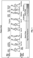
- the human knee must generate and dissipate a range of power during different ambulation tasks and the different phases of each task ( FIG. 1 ). For example, during level ground walking the knee must stay “locked” during stance phase to keep the knee from buckling under load. After toe-off the knee must become “loose” to allow it to flex during swing phase to provide ground clearance for the foot. As it extends, energy must be dissipated quickly and smoothly to stop the knee in the fully extended position just prior to heel contact (heel strike). On the other hand, climbing stairs requires positive power to lift the entire weight of the user up and over each step in a controlled manner.
- Prosthetic knees are typically either passive, active or semi-active. Passive devices are compact devices that provide very limited function, usually only useful for level ground walking. They have a fixed static or passively varied resistance at the joint that allows for limited swing phase control, and cannot adapt to different walking speeds. Additionally, during stance phase there is a risk of buckling, as there is little resistance at the knee. Some passive knees employ a four-bar mechanism (polycentric knees) or a load activated mechanical brake to keep the leg straight during stance phase. However, these devices still require that the prosthesis alignment be shifted to ensure the weight line falls in front of the knee axis and are still prone to buckling in some situations.
- Semi-active knees can actively vary the knee resistance to adapt to different ambulation modes and to provide better stance and swing control.
- the Ottobock C-leg uses a hydraulic damper with valves that are adjusted via micro-controller to alter the knee resistance.
- Semi-active knees offer greater stability than passive knees and more natural gait dynamics than passive and active knees. They require very little electrical power to operate. However, they still require charging and they do not provide net positive power for stairs and standing up from a chair.
- Active knees provide net positive power for climbing stairs and ramps and getting up from a seated position.
- the powered actuator controls all phases of gait.
- the knee is mainly dissipating mechanical energy.
- Active knees typically dissipate energy by applying torque (current) through the motor to oppose motion, which can consume significant electrical energy.
- torque current
- active devices there is often a tradeoff between torque and speed. For example, a device that is strong enough to power up stairs may be slow during walking. Conversely, a knee that is fast enough for a brisk walk may not provide as much assistance during stair climb.
- active devices are much heavier and larger than passive and semi-active devices and require frequent battery charging.
- one end (150) of the assistive device 100 may be provided with means for attaching the assistive device 100 to a residual limb of a user and may define a pyramid interface or fastener (e.g., "16" of the ⁇ 381 patent) for attaching to a socket (e.g., "60" of the ⁇ 381 Patent) or to an implanted component of the user.
- a pyramid interface or fastener e.g., "16" of the ⁇ 381 patent
- socket e.g., "60" of the ⁇ 381 Patent
- Other suitable attachment means may be utilized.
- the other end (152) of the assistive device 100 may be configured for attachment to a pylon and/or a foot (e.g., "90" of the ⁇ 381 patent).
- the assistive device 100 is responsive to the technical problems and drawbacks of conventional prosthetics and assistive devices described herein.
- the assistive device 100 implements and selectively engages separate control systems (collectively hybrid control systems 101), including an active control system 102 and a passive control system 104, to control "active" and "passive” tasks, respectively.
- "active" tasks refer to tasks that require net positive energy
- "passive" tasks refer to net zero or negative energy tasks.
- FIG. 2B described herein and in the following text the focus mainly relates to one possible embodiment of the assistive device 100 taking the form of a lower limb prosthesis including a knee joint.
- hybrid or dynamic nature of the hybrid control systems 101 and the features associated with the novel selective engagement of the active control system 102 and the passive control system 104 described herein may be applied for any other embodiment of the assistive device 100 configured for movement or assistance of any artificial joint; including, by non-limiting example, an artificial elbow joint, or the like.
- the hybrid control systems 101 may be applied to an exoskeleton or a powered orthosis to augment the movement of a natural joint.
- the hybrid control systems 101 can be implemented to control one or more of a mechanical actuator 112 or other mechanical and/or electromechanical components, which may be configured to facilitate movement of an artificial joint 114 (e.g., knee joint).
- the assistive device 100 switches between the two hybrid control systems 101 of FIG. 2A seamlessly and quickly, based on the needs for a given task.
- the "active" control system 102 When net positive energy is needed, for instance when powering up stairs or standing from a seated position, the "active" control system 102 is engaged. However, if net zero or negative energy is needed, the "active" control system 102 is disabled and the “passive" control system 104 engaged.
- the "passive" control system 104 functions similar to many commercial "semi-active" knees, for example Ottobock's C-Leg.
- the assistive device 100 does not limit a particular ambulation mode to a specific one of the hybrid control systems 101.
- both of the "active" control system 102 and the “passive” control system 104 can be used. While the “active" control system 102 typically consumes more electrical energy, the “passive” control system 104 consumes minimal electrical energy. Being adapted to engage the "active" control system 102 only when needed or desired, the assistive device 100 is much more efficient than fully active devices (e.g., fully active knee devices). In addition, the "passive" control system 104 can typically handle higher speeds associated with many passive tasks, such as brisk walking. Compared to active devices or active knees, when the "passive" control system 104 is used, it provides for more quiet, efficient operation and more natural joint dynamics.
- the "passive" control system 104 implements a form of rheostatic dynamic braking, and a novel control strategy to quickly vary the amount of power dissipated at, e.g., the joint 114 (and knee joint 300).
- Dynamic braking uses an electromechanical motor as a generator to convert mechanical energy into electrical energy.
- the electrical energy dissipates as thermal energy through the motor windings, which resists motion of the joint.
- power is dissipated without consuming additional electrical power from a battery of the assistive device 100.
- Prosthetic knees are good candidates for rheostatic dynamic braking, as heavy braking is needed only periodically, and thus there is no risk of overheating the motor windings.
- embodiments of the assistive device 100 include a continuously variable transmission (CVT) 106 defined by the mechanical actuator 112 or one or more actuating components.
- the CVT 106 is used to adjust the mechanical transmission ratio to optimize the mechanical power profile of the joint for "active" and "passive" tasks.
- the dynamics of a human knee require speeds and torques that are hard to replicate with an electro-mechanical motor alone.
- a mechanical transmission is typically required to produce useful dynamics at the knee joint of a lower limb prosthetic.
- a mechanical transmission uses mechanical advantage to reduce or amplify the speed and torque. The amount of reduction and amplification is defined by the transmission's speed or gear-ratio.
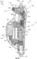
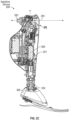
- a lower limb embodiment of the assistive device 100 is shown, designated lower limb device 200 and defining a knee joint 300.
- the lower limb device 200 may define a prosthetic or an orthosis for movement/motion assistance.
- the lower limb device 200 may generally be implemented, for example, for a user that is entirely devoid of a natural knee and lower limb such as shown in FIGS. 3-6 of the ⁇ 381 patent referenced herein or alternately in the manner shown in FIG. 28 of the ⁇ 381 patent.
- a first end 350 of the lower limb device 200 may be provided with means for attachment of the lower limb device 200 to a residual limb of a user and may define a pyramid interface or fastener (e.g., "16" of the ⁇ 381 patent) for attaching to a socket (e.g., "60” of the ⁇ 381 Patent) or to an implanted component of the user. Other suitable attachment means may be utilized.
- a second end 352 of the lower limb device 200 may be configured for attachment to a pylon and/or a foot (e.g., "90" of the ⁇ 381 patent, and shown as “360” in FIG. 2C ).
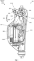
- the lower limb assistive device 200 includes one or more actuating components 301 (mechanical and/or electro-mechanical) for actuating or otherwise engaging the knee joint 300 and other aspects of the lower limb assistive device 200 including a brushless DC motor 201 (e.g., Maxon Motor EC-4pole 24V, 120W) which converts electrical to mechanical energy in the form of rotational motion.
- the rotational motion is transmitted to a roller screw 205 (e.g., Rollvis, pitch diameter 4.5mm, lead 2 mm) through a timing belt transmission 203.
- the roller screw 205 converts the rotational motion to linear motion
- a slider crank 217 including a first portion 219A of the slider crank 217 and a second portion 219B, converts the linear motion back to rotational motion at the knee joint 300.
- the slider crank 217 includes a connecting rod 208, which is pinned to a roller screw nut 207 at a first rod pivot 220. The other end of the connecting rod 208 is pinned to the slider crank 217 at a second rod pivot 222.
- the roller screw nut 207 transmits linear motion through the connecting rod 208 to the second rod pivot 222, which rotates the slider crank 217 around the crank pivot 218B or the knee axis 218C. Further details of this actuation system can be found in the ⁇ 381 patent herein incorporated by reference, specifically, the "four-bar linkage" system disclosed therein and shown for example in FIGS. 14A and 14B.
- the CVT 106 mechanism modifies the transmission ratio of the slider crank 217 by changing the distance 302 between the second rod pivot 222 and the crank pivot 218B on the first portion 219A of the slider crank 217.
- a second brushless DC motor 211 e.g., Maxon Motor EC22 24V
- the lead screw nut 209 is connected to the second rod pivot 222.
- Linear motion at the lead screw nut 209 changes the length 304 of the slider crank 217 moment arm, by changing the distance (304) between the second rod pivot 222 and the crank pivot 218B.
- Further details of the CVT mechanism 106 can be found in the ⁇ 381 patent herein incorporated by reference.
- the total speed ratio of the lower limb device 200 is a function of both the slider crank 217 moment arm length and the knee joint 300 position (see change/movement of knee joint 300 position shown in FIG. 6 ).
- the total transmission ratio from the axis 306 of symmetry that runs through the center of the motor 201 to the knee axis 218C can be found using Equation 1, shown in FIG. 5 .
- the hybrid control systems 101 described herein may be implemented to control aspects of the lower limb assistive device 200 (and may be implemented fully on board the lower limb assistive device 200, partially on-board the lower limb assistive device 200, or totally off-board and in communication with the lower limb assistive device 200 via any wired or wireless communication form).
- feedback from the lower limb assistive device 200 is provided to the hybrid control systems 101 using an array of electro-mechanical sensors, designated sensors 108 in FIG. 2A and sensors (202, 227, 224, 215, 223) in FIG. 8 .
- the lower limb device 200 may include a Hall-based absolute encoder 224 positioned at the knee axis 218C to measure a knee joint angle (A).
- the knee joint angle (A) is defined at the intersection between the longitudinal axis 306 of the motor 201, and a longitudinal axis 354 of the first end 350; noting that the first end 350 is ordinarily fixed to a residual limb or socket.
- the knee joint angle (A) In a standing or extended position as shown in FIGS. 2B , 3 , and 4 , the knee joint angle (A) is approximately zero degrees (longitudinal axis 306 and longitudinal axis 354 generally extend in parallel and do not intersect).
- the knee joint angle (A) of the lower limb assistive device 200 is approximately ninety degrees due to a shift in position of the first end 350 relative to the motor 201 that results in the intersection shown between the longitudinal axis 306 and the longitudinal axis 354 (at about a 90 degree angle).
- the lower limb device 200 may include a Hall-based incremental encoder 215 attached to the main DC motor 201 to measure motor position, and a second Hall-based incremental encoder 223 attached to the secondary DC motor 211 to measure the slider crank 217 moment arm length 304.
- the lower limb device 200 may include a six axis load cell 202 (e.g., Sunrise Instruments M3713D) positioned as shown in FIG. 2B to measure ground level reaction forces and moments.
- an Inertial Measurement Unit (IMU) 227 e.g., TDK MPU-9250 may be used to measure knee acceleration and inclination angles.
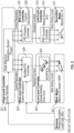
- the control of the lower limb device 200 may be driven by three tiers of controllers; specifically, one or more of a high-level controller 231, a mid-level controller 232, and a low-level controller 233; and each tier of controllers may respectively include an "active" controller and a "passive” controller.
- the high-level controller 231 control may be implemented on a Linux based computer-on-module 225 (e.g., Gumstix Overo Air) which runs a state machine that analyzes sensor feedback data from the lower limb device 200 and determines a proper state of the knee joint 300 and lower limb assistive device 200.
- a Linux based computer-on-module 225 e.g., Gumstix Overo Air
- sensor feedback data received by high level controller 231 includes load, acceleration, and gyroscopic data as determined by load cell 202 and IMU 227, and high level controller 231 determines a state of the knee lower limb device 200 based on the sensor feedback data. For instance, the state machine determines if the lower limb device 200 is in the stance or free swing phase of walking (shown in FIG. 1 ), based on ground reaction forces detected by the load cell 202, as well as the position of the lower limb device 200 and a shank inclination angle detected by the IMU 227. The state machine also must distinguish between different modes of ambulation (i.e. stair ascent, level ground walking, ramp descent, etc.). Based on the determined state of the knee joint 300, the high-level controller 231 sends specific control parameters to the mid-level controller 232 to control active operations and passive operations of the lower limb device 200 such as desired currents applied to motors 201 and 211
- the mid-level controller/s 232 as described above may include an "active" controller ( FIG. 9 ) and “passive” controller ( FIG. 8 ).
- the mid-level controllers 232 may be run on a custom printed circuit board (PCB) 228 with, e.g., an ESP32 based microcontroller, such as a Pycom Wipy 2.0, running Micropython.
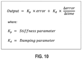
- the mid-level controllers 232 may include an "active" controller ( FIG. 9 ) including an impedance controller, which accepts control parameters including desired knee angle, stiffness and dampening as inputs from the high-level controller 231.
- Impedance controller of the mid-level controllers 232 calculate a desired motor current based on control parameters received from the high level controller 231, which is subsequently communicated to the low-level controller 233 ( FIG. 10 ) for direct control of main motor 201.
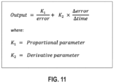
- the "passive" controller ( FIG. 8 ) of the mid-level controllers 232 uses a modified PD control approach, which accepts a desired knee angle and two braking factors as inputs from the high-level controller 231 ( FIG. 11 ).
- the mid-level controller 232 calculates the desired motor braking of the lower limb device 200, which is discussed in more detail in the following paragraphs ("Dynamic Braking Control").
- the lower limb assistive device 200 further includes one or more of a battery 310, which may be positioned along the PCB 228 as shown and in electrical communication with the same.
- the lower limb device 200 may include a commercial servo driver 229 (e.g., Elmo Gold Twitter G-TWI 30/60SE).
- Servo driver 229 is the "active" controller of the low-level controllers 233.
- the motor windings of main motor 201 are connected directly to the servo driver 229, and the DC motor 201 can be controlled by modulating the current drawn through the motor windings, which is directly related to motor torque output.
- Low-level controller 233 receives a desired motor current from the midlevel controller 232.
- the low-level controller 233 uses its own PD control approach to set the actual motor current output based on the desired motor current received from the midlevel controller 232.
- dynamic braking is the use of an electric motor to convert mechanical energy of a rotating shaft into electrical and thermal energy. This is typically accomplished by connecting winding phases of a motor to a common ground. The motor then acts as a generator. Turning the motor shaft generates electrical energy and a temporary resistance to a change in current, creating a back electromotive force (back EMF). The back EMF acts to resist motor shaft rotation, effectively braking the motor.
- back EMF back electromotive force
- the electrical energy generated is dissipated as heat inside of the motor.
- Regenerative dynamic braking is an alternative method that returns the energy to a battery, but requires more complex electronics and is more expensive than rheostatic dynamic braking.
- Dynamic braking is a well-known method for braking electro motors. Many commercial servo drivers offer the ability to enable a dynamic brake to stop a motor. However, with most available systems, the amount of braking cannot be varied, and the brake is either fully ON or fully OFF.
- the amount of current through the resistor is directly proportional to the braking torque, and so the motor braking torque is increased by minimizing the braking resistor's resistance value. Additionally, increased braking increases the amount of electrical power dissipated through the braking circuit. In order to handle sufficient braking, a braking resistor must minimize resistance and maximize its power rating.
- the assistive device 100 uses an alternative method for controlling the amount of dynamic braking, designated dynamic braking control 110 in FIG 2A .
- dynamic braking control 110 uses an alternative method for controlling the amount of dynamic braking, designated dynamic braking control 110 in FIG 2A .
- the current through the windings of main motor 201 is varied using Pulse Width Modulation (PWM).
- PWM Pulse Width Modulation
- Each winding phase of main motor 201 is connected to a switching transistor that couples and decouples the winding phase to and from a common ground. This varies the total current through the windings.
- the transistors are switched ON and OFF at very high frequencies using a digital signal.
- Two level PWM is a digital signal that has two states: high and low (ON and OFF).
- the frequency is the rate of state change cycles per second in Hertz (Hz).
- Duty cycle is the amount of time the signal stays ON during each cycle. Duty cycle is typically expressed as a percentage of one cycle. For example, a duty cycle of 30% and frequency of 1 Hz describes a signal that cycles once every second, or one second per cycle. For each cycle, the signal stays ON for 0.3 s and OFF for 0.7 s ( FIG. 11 ).
- the lower limb device 200 uses a three-phase brushless motor. This requires three switching transistors to short each winding phase of the three winding phases to common ground for dynamic braking.
- Two main types of transistors are contemplated: enhancement and depletion mode MOSFETs. Enhancement mode MOSFETs have the advantage of lower "on state" resistances, smaller sizes, as well as wider availability. However, enhancement mode MOSFETs default to the OFF state at zero gate-source voltage. Depletion mode MOSFETs typically have higher on state resistance, have limited availability, but default to an ON state at zero gate-source voltage.
- the lower limb device 200 uses two separate sets of MOSFETs to control braking ( FIG. 12 ).
- the "passive" mid-level controller 232 uses a low-resistance enhancement mode MOSFET to modulate braking.
- the enhancement mode MOSFETs open and the depletion mode MOSFETs close, shorting/coupling the winding phases of main motor 201 to ground. This allows for static braking of the assistive device 200 even when unpowered. This is important in order to keep the assistive device 200 from becoming completely loose, which can help to prevent knee buckling or falls. Since in the OFF state, braking requirements are not as high, the higher resistance depletion mode MOSFET provides sufficient braking.
- the depletion mode transistor is used solely to provide braking at the device 200 when power is lost.
- the depletion mode is always open.
- the depletion mode transistor closes, shorting/coupling the (winding phases) of main motor 201 to ground.
- the enhancement mode transistor is pulsed with the PWM signal to vary an amount of braking in passive mode. In active mode, the enhancement mode transistor is always open.
- the mid-level "passive" controller 232 uses a PWM signal with a frequency of 70,000 Hz.
- the mid-level controller 232 modulates the duty cycle with an update frequency of up to 400 Hz. This allows for very responsive control of the amount of braking.
- full stance and swing phase control, as well as stair descent resistance can be achieved using this method.
- the PWM duty cycle can be set to 100%, for maximum knee resistance to keep the knee "locked”.
- the PWM duty cycle is immediately reduced to lower the knee resistance and allow it to smoothly flex during swing phase. Dynamic braking control using PWM requires only the power required for the microcontroller 232.
- the mid-level controller In order to switch between "passive” and “active” control, the mid-level controller opens and closes the enhancement mode MOSFETs accordingly.
- the three motor winding phases of motor 201 are connected to the MOSFETs, as well as the servo driver terminals. When the MOSFETs are closed, the winding phases are coupled/shorted directly to a common ground. When the MOSFETs are open, the motor winding phases pass directly to the servo driver 229 terminals for control of the motor 201.
- the mid-level controller 232 includes logic that opens the MOSFETs and enables the servo driver 229 when "active" control is needed.
- the mid-level controller 232 disables the servo driver 229 and closes the MOSFETs when "passive" control is needed.
- the gate of each MOSFET is tied to a Safe Torque Off (STO) of the servo driver 229.
- STO is a basic driver safety feature that acts as a safe stop. Digital logic inputs enable and disable the STO. When STO logic is low, the servo driver 229 is disabled. Connecting the logic for the enhancement and depletion MOSFET gates to the servo driver's STO lines significantly reduces the likelihood of shorting the motor winding phases to ground while the servo driver 229 is active.
- the CVT 106 also can control the amount of knee resistance.
- the knee speed, knee resistance and the electrical power dissipation profile can be optimized for different ambulation modes and users. For example, for descending stairs, increasing the CVT gear ratio allows for increased support of the user as the knee joint 300 flexes. Reducing the CVT gear ratio can increase the output knee speed for fast walking.
- the assistive device can optimize performance for a wide operating range, providing increased efficiency and functionality to the user.
- the assistive device uses separate control systems to control "active" and "passive” tasks. Additionally, by combining this with a CVT mechanism 106, the present device 200 can be optimized for a wide range of tasks.
- Prosthetic knees including active knees, mainly perform energy dissipating tasks such as standing, walking and descending stairs and ramps.
- many users could benefit from the ability to produce net positive power at the knee joint for tasks such as stair climbing and standing from the seated position. This is especially true for the elderly population.
- existing prosthetic knee devices that produce net positive power are very heavy and can be too slow for many tasks.
- the assistive device allows for "active" power generation when needed, but otherwise switches to "passive” control. Since the "passive" control consumes significantly less electrical power, the total knee operation is much more efficient that a fully active device.
- the present design of the lower limb assistive device 200 allows the system to minimize weight and efficiency by optimizing the active mode actuation system for high-torque, low speed operation.
Landscapes
- Health & Medical Sciences (AREA)
- Engineering & Computer Science (AREA)
- Transplantation (AREA)
- Biomedical Technology (AREA)
- Public Health (AREA)
- General Health & Medical Sciences (AREA)
- Animal Behavior & Ethology (AREA)
- Veterinary Medicine (AREA)
- Vascular Medicine (AREA)
- Life Sciences & Earth Sciences (AREA)
- Oral & Maxillofacial Surgery (AREA)
- Cardiology (AREA)
- Heart & Thoracic Surgery (AREA)
- Orthopedic Medicine & Surgery (AREA)
- Business, Economics & Management (AREA)
- General Business, Economics & Management (AREA)
- Epidemiology (AREA)
- Medical Informatics (AREA)
- Primary Health Care (AREA)
- Manufacturing & Machinery (AREA)
- Rehabilitation Tools (AREA)
Applications Claiming Priority (3)
| Application Number | Priority Date | Filing Date | Title |
|---|---|---|---|
| US201962943913P | 2019-12-05 | 2019-12-05 | |
| PCT/US2020/063668 WO2021113847A1 (fr) | 2019-12-05 | 2020-12-07 | Dispositif d'assistance à systèmes de commande hybrides |
| EP20895951.0A EP4069157A4 (fr) | 2019-12-05 | 2020-12-07 | Dispositif d'assistance à systèmes de commande hybrides |
Related Parent Applications (1)
| Application Number | Title | Priority Date | Filing Date |
|---|---|---|---|
| EP20895951.0A Division EP4069157A4 (fr) | 2019-12-05 | 2020-12-07 | Dispositif d'assistance à systèmes de commande hybrides |
Publications (2)
| Publication Number | Publication Date |
|---|---|
| EP4438013A2 true EP4438013A2 (fr) | 2024-10-02 |
| EP4438013A3 EP4438013A3 (fr) | 2024-12-18 |
Family
ID=76222690
Family Applications (2)
| Application Number | Title | Priority Date | Filing Date |
|---|---|---|---|
| EP20895951.0A Pending EP4069157A4 (fr) | 2019-12-05 | 2020-12-07 | Dispositif d'assistance à systèmes de commande hybrides |
| EP24194718.3A Pending EP4438013A3 (fr) | 2019-12-05 | 2020-12-07 | Dispositif d'assistance avec systèmes de commande hybrides |
Family Applications Before (1)
| Application Number | Title | Priority Date | Filing Date |
|---|---|---|---|
| EP20895951.0A Pending EP4069157A4 (fr) | 2019-12-05 | 2020-12-07 | Dispositif d'assistance à systèmes de commande hybrides |
Country Status (3)
| Country | Link |
|---|---|
| US (1) | US20240350284A1 (fr) |
| EP (2) | EP4069157A4 (fr) |
| WO (1) | WO2021113847A1 (fr) |
Families Citing this family (1)
| Publication number | Priority date | Publication date | Assignee | Title |
|---|---|---|---|---|
| DE102023120961A1 (de) | 2023-08-07 | 2025-02-13 | Otto Bock Healthcare Products Gmbh | Orthopädietechnische Gelenkeinrichtung und Verfahren zu deren Steuerung |
Citations (1)
| Publication number | Priority date | Publication date | Assignee | Title |
|---|---|---|---|---|
| US10357381B2 (en) | 2014-12-08 | 2019-07-23 | Rehabilitation Instititute of Chicago | Powered and passive assistive device and related methods |
Family Cites Families (6)
| Publication number | Priority date | Publication date | Assignee | Title |
|---|---|---|---|---|
| DE19859931A1 (de) * | 1998-12-24 | 2000-07-06 | Biedermann Motech Gmbh | Beinprothese mit einem künstlichen Kniegelenk und Verfahren zur Steuerung einer Beinprothese |
| WO2001072245A2 (fr) * | 2000-03-29 | 2001-10-04 | Massachusetts Institute Of Technology | Prothese de genou adaptable a la vitesse et adaptable au patient |
| US20060249315A1 (en) * | 2005-03-31 | 2006-11-09 | Massachusetts Institute Of Technology | Artificial human limbs and joints employing actuators, springs, and variable-damper elements |
| SE528516C2 (sv) * | 2005-04-19 | 2006-12-05 | Lisa Gramnaes | Kombinerat aktivt och passivt benprotessystem samt en metod för att utföra en rörelsecykel med ett sådant system |
| WO2008080231A1 (fr) * | 2007-01-05 | 2008-07-10 | Victhom Human Bionics Inc. | Mécanisme d'actionnement d'une articulation pour dispositif prothétique ou orthétique à transmission flexible |
| WO2013188510A2 (fr) * | 2012-06-12 | 2013-12-19 | Iwalk, Inc. | Dispositif prothétique, orthétique ou d'exosquelette |
-
2020
- 2020-12-07 WO PCT/US2020/063668 patent/WO2021113847A1/fr not_active Ceased
- 2020-12-07 EP EP20895951.0A patent/EP4069157A4/fr active Pending
- 2020-12-07 EP EP24194718.3A patent/EP4438013A3/fr active Pending
-
2024
- 2024-06-28 US US18/759,244 patent/US20240350284A1/en active Pending
Patent Citations (1)
| Publication number | Priority date | Publication date | Assignee | Title |
|---|---|---|---|---|
| US10357381B2 (en) | 2014-12-08 | 2019-07-23 | Rehabilitation Instititute of Chicago | Powered and passive assistive device and related methods |
Also Published As
| Publication number | Publication date |
|---|---|
| US20240350284A1 (en) | 2024-10-24 |
| EP4069157A1 (fr) | 2022-10-12 |
| US20230050006A1 (en) | 2023-02-16 |
| EP4069157A4 (fr) | 2023-10-18 |
| WO2021113847A1 (fr) | 2021-06-10 |
| EP4438013A3 (fr) | 2024-12-18 |
Similar Documents
| Publication | Publication Date | Title |
|---|---|---|
| AU2007223733B2 (en) | Power generating leg | |
| US11026815B2 (en) | Controlling power in a prosthesis or orthosis based on predicted walking speed or surrogate for same | |
| US7485152B2 (en) | Prosthetic leg having electronically controlled prosthetic knee with regenerative braking feature | |
| Boehler et al. | Design, implementation and test results of a robust control method for a powered ankle foot orthosis (AFO) | |
| US8562691B2 (en) | Training device | |
| US20090259320A1 (en) | Generator for prosthesis and orthosis | |
| Lenzi et al. | Design and preliminary testing of the RIC hybrid knee prosthesis | |
| KR102826532B1 (ko) | 웨어러블 장치의 사용자에게 저항력을 제공하는 방법 및 장치 | |
| KR20250107139A (ko) | 웨어러블 장치의 사용자에게 저항력을 제공하는 방법 및 장치 | |
| US20240350284A1 (en) | Assistive device with hybrid control systems | |
| Oymagil et al. | Control of a regenerative braking powered ankle foot orthosis | |
| US12616590B2 (en) | Assistive device with hybrid control systems | |
| US20230270571A1 (en) | Powered-on passive knee prosthesis system | |
| Yuan et al. | A hierarchical control scheme for smooth transitions between level ground and ramps with a robotic transtibial prosthesis | |
| Downes et al. | Distributed control of an electrically powered hip orthosis | |
| Boiadjiev et al. | Control system for data acquisition and processing of ankle-foot orthosis | |
| Veneva | Design and implementation of device for control of active ankle-foot orthosis | |
| Al-angari et al. | A two degree-of-freedom microprocessor based extended physiological proprioception (EPP) controller for upper limb prostheses | |
| Feng et al. | Robotic transtibial prosthesis with damping control improves amputee's level-ground walking at different speeds |
Legal Events
| Date | Code | Title | Description |
|---|---|---|---|
| PUAI | Public reference made under article 153(3) epc to a published international application that has entered the european phase |
Free format text: ORIGINAL CODE: 0009012 |
|
| STAA | Information on the status of an ep patent application or granted ep patent |
Free format text: STATUS: THE APPLICATION HAS BEEN PUBLISHED |
|
| AC | Divisional application: reference to earlier application |
Ref document number: 4069157 Country of ref document: EP Kind code of ref document: P |
|
| AK | Designated contracting states |
Kind code of ref document: A2 Designated state(s): AL AT BE BG CH CY CZ DE DK EE ES FI FR GB GR HR HU IE IS IT LI LT LU LV MC MK MT NL NO PL PT RO RS SE SI SK SM TR |
|
| REG | Reference to a national code |
Ref country code: DE Ref legal event code: R079 Free format text: PREVIOUS MAIN CLASS: A61F0002660000 Ipc: A61F0002600000 |
|
| PUAL | Search report despatched |
Free format text: ORIGINAL CODE: 0009013 |
|
| AK | Designated contracting states |
Kind code of ref document: A3 Designated state(s): AL AT BE BG CH CY CZ DE DK EE ES FI FR GB GR HR HU IE IS IT LI LT LU LV MC MK MT NL NO PL PT RO RS SE SI SK SM TR |
|
| RIC1 | Information provided on ipc code assigned before grant |
Ipc: A61F 2/70 20060101ALI20241114BHEP Ipc: A61F 2/66 20060101ALI20241114BHEP Ipc: A61F 2/64 20060101ALI20241114BHEP Ipc: A61F 2/60 20060101AFI20241114BHEP |
|
| STAA | Information on the status of an ep patent application or granted ep patent |
Free format text: STATUS: REQUEST FOR EXAMINATION WAS MADE |
|
| 17P | Request for examination filed |
Effective date: 20250618 |
|
| GRAP | Despatch of communication of intention to grant a patent |
Free format text: ORIGINAL CODE: EPIDOSNIGR1 |
|
| STAA | Information on the status of an ep patent application or granted ep patent |
Free format text: STATUS: GRANT OF PATENT IS INTENDED |