EP4438063B1 - Adaptateur pour relier un objet à corps creux à un appareil pour le rinçage intérieur d'objets à corps creux - Google Patents
Adaptateur pour relier un objet à corps creux à un appareil pour le rinçage intérieur d'objets à corps creux Download PDFInfo
- Publication number
- EP4438063B1 EP4438063B1 EP23166186.9A EP23166186A EP4438063B1 EP 4438063 B1 EP4438063 B1 EP 4438063B1 EP 23166186 A EP23166186 A EP 23166186A EP 4438063 B1 EP4438063 B1 EP 4438063B1
- Authority
- EP
- European Patent Office
- Prior art keywords
- adapter
- outer part
- locking
- opening
- hollow
- Prior art date
- Legal status (The legal status is an assumption and is not a legal conclusion. Google has not performed a legal analysis and makes no representation as to the accuracy of the status listed.)
- Active
Links
Images






Classifications
-
- A—HUMAN NECESSITIES
- A61—MEDICAL OR VETERINARY SCIENCE; HYGIENE
- A61C—DENTISTRY; APPARATUS OR METHODS FOR ORAL OR DENTAL HYGIENE
- A61C19/00—Dental auxiliary appliances
- A61C19/002—Cleaning devices specially adapted for dental instruments
-
- A—HUMAN NECESSITIES
- A61—MEDICAL OR VETERINARY SCIENCE; HYGIENE
- A61B—DIAGNOSIS; SURGERY; IDENTIFICATION
- A61B90/00—Instruments, implements or accessories specially adapted for surgery or diagnosis and not covered by any of the groups A61B1/00 - A61B50/00, e.g. for luxation treatment or for protecting wound edges
- A61B90/70—Cleaning devices specially adapted for surgical instruments
-
- A—HUMAN NECESSITIES
- A61—MEDICAL OR VETERINARY SCIENCE; HYGIENE
- A61C—DENTISTRY; APPARATUS OR METHODS FOR ORAL OR DENTAL HYGIENE
- A61C1/00—Dental machines for boring or cutting ; General features of dental machines or apparatus, e.g. hand-piece design
- A61C1/08—Machine parts specially adapted for dentistry
- A61C1/12—Angle hand-pieces
-
- A—HUMAN NECESSITIES
- A61—MEDICAL OR VETERINARY SCIENCE; HYGIENE
- A61L—METHODS OR APPARATUS FOR STERILISING MATERIALS OR OBJECTS IN GENERAL; DISINFECTION, STERILISATION OR DEODORISATION OF AIR; CHEMICAL ASPECTS OF BANDAGES, DRESSINGS, ABSORBENT PADS OR SURGICAL ARTICLES; MATERIALS FOR BANDAGES, DRESSINGS, ABSORBENT PADS OR SURGICAL ARTICLES
- A61L2103/00—Materials or objects being the target of disinfection or sterilisation
- A61L2103/15—Laboratory, medical or dentistry appliances, e.g. catheters or sharps
-
- A—HUMAN NECESSITIES
- A61—MEDICAL OR VETERINARY SCIENCE; HYGIENE
- A61L—METHODS OR APPARATUS FOR STERILISING MATERIALS OR OBJECTS IN GENERAL; DISINFECTION, STERILISATION OR DEODORISATION OF AIR; CHEMICAL ASPECTS OF BANDAGES, DRESSINGS, ABSORBENT PADS OR SURGICAL ARTICLES; MATERIALS FOR BANDAGES, DRESSINGS, ABSORBENT PADS OR SURGICAL ARTICLES
- A61L2202/00—Aspects relating to methods or apparatus for disinfecting or sterilising materials or objects
- A61L2202/10—Apparatus features
- A61L2202/12—Apparatus for isolating biocidal substances from the environment
-
- A—HUMAN NECESSITIES
- A61—MEDICAL OR VETERINARY SCIENCE; HYGIENE
- A61L—METHODS OR APPARATUS FOR STERILISING MATERIALS OR OBJECTS IN GENERAL; DISINFECTION, STERILISATION OR DEODORISATION OF AIR; CHEMICAL ASPECTS OF BANDAGES, DRESSINGS, ABSORBENT PADS OR SURGICAL ARTICLES; MATERIALS FOR BANDAGES, DRESSINGS, ABSORBENT PADS OR SURGICAL ARTICLES
- A61L2202/00—Aspects relating to methods or apparatus for disinfecting or sterilising materials or objects
- A61L2202/10—Apparatus features
- A61L2202/12—Apparatus for isolating biocidal substances from the environment
- A61L2202/123—Connecting means
-
- A—HUMAN NECESSITIES
- A61—MEDICAL OR VETERINARY SCIENCE; HYGIENE
- A61M—DEVICES FOR INTRODUCING MEDIA INTO, OR ONTO, THE BODY; DEVICES FOR TRANSDUCING BODY MEDIA OR FOR TAKING MEDIA FROM THE BODY; DEVICES FOR PRODUCING OR ENDING SLEEP OR STUPOR
- A61M39/00—Tubes, tube connectors, tube couplings, valves, access sites or the like, specially adapted for medical use
- A61M39/10—Tube connectors; Tube couplings
- A61M2039/1027—Quick-acting type connectors
-
- A—HUMAN NECESSITIES
- A61—MEDICAL OR VETERINARY SCIENCE; HYGIENE
- A61M—DEVICES FOR INTRODUCING MEDIA INTO, OR ONTO, THE BODY; DEVICES FOR TRANSDUCING BODY MEDIA OR FOR TAKING MEDIA FROM THE BODY; DEVICES FOR PRODUCING OR ENDING SLEEP OR STUPOR
- A61M39/00—Tubes, tube connectors, tube couplings, valves, access sites or the like, specially adapted for medical use
- A61M39/10—Tube connectors; Tube couplings
- A61M39/1011—Locking means for securing connection; Additional tamper safeties
Definitions
- instruments with difficult-to-access cavities are used.
- examples of such instruments include handpieces, contra-angles, and turbines.
- microorganisms tend to accumulate in such difficult-to-access cavities, such as crevices, grooves, or pores, where they also find sufficient nutrients, such cavities pose a particular challenge with regard to cleaning, disinfection, sterilization, and drying.
- Washer-disinfectors typically perform internal rinsing of medical and dental instruments to kill microorganisms in hard-to-reach cavities and remove contamination from within the instruments.
- Adapters are often provided for this purpose, allowing the respective instruments to be connected to the washer-disinfectors.
- Transmission instruments such as handpieces and contra-angles also have a drive system located inside the transmission instrument, which requires separate maintenance.
- Manufacturers of transmission instruments typically recommend lubricating the instrument with a specially formulated dental oil at least once a day after cleaning and disinfection (but before sterilization).
- This dental oil is usually only applied to one drive channel of the transmission instrument, as only the drive channel contains moving parts that require maintenance with dental oil.
- so-called spray channels in transmission instruments are only cleaned and disinfected, but not supplied with dental oil. The separation of spray and and drive channels, an isolated supply of dental oil to the moving drive elements is possible.
- the adapters used to connect the transmission instruments to a cleaning and disinfection device typically also have different channels for separate contacting of the spray and drive channels in the transmission instruments.
- the adapters used to connect instruments to a washer-disinfector must provide sufficient holding force to reliably withstand the rinsing pressure applied by the washer-disinfector. Furthermore, they should enable quick and user-friendly connection and disconnection of the instrument to/from the washer-disinfector. Furthermore, a reliable supply of the instrument's channels with the intended medium (in particular, only rinsing fluid or rinsing fluid and dental oil) and, if necessary, sealing from the environment should be ensured. Finally, rinsing shadows should be minimized to prevent uncleaned areas of the transfer instruments or other instruments.
- the adapters' media channels are also used to direct drying air into previously cleaned and disinfected objects. This drying air serves to accelerate the drying process or reduce residual moisture. A basic distinction is made between internal and external drying of the objects to be dried.
- the drying air is passed through the internal lumen of an instrument to be dried. Drying is achieved by the inherent heat of the instruments resulting from thermal disinfection and is accelerated by the drying air passing through the instruments.
- the DE 296 24 425 U1 Describes a rinsing device for internally rinsing and holding dental handpieces and contra-angles, which is arranged in an instrument insert, a tool cart, or the like.
- the instrument insert can be inserted separately in the rinsing chamber of a cleaning device, such as a program-controlled dishwasher, and is supplied with pre-filtered rinsing and cleaning fluid.
- the rinsing device in the instrument insert is designed as a multi-part holder with a removable microfilter for the rinsing and cleaning fluid.
- the EP 2 946 749 A1 also describes a device for the internal rinsing of dental equipment, such as turbines, handpieces, and contra-angles.
- This device also has a coupling device for connecting the equipment to a connection piece connected to a connection piece of a pipeline.
- the coupling device has a clamping device for securing the position of the equipment connected to the coupling device.
- the coupling device is designed to be movable relative to the connection piece for actuating the clamping device.
- the DE 10 2021 119 351 A1 describes an adaptation device for receiving medical cleaning items.
- This adaptation device has a sleeve unit in which a cavity is formed.
- the sleeve unit has a connecting section for fluid-mechanically connecting the cavity to a feed device of a rinsing basket of a cleaning device and a sleeve opening opposite the connecting section.
- the adaptation device has a holder device that serves to hold the medical cleaning items in a position coupled to the carrier device.
- the adaptation device comprises an elastic means that is arranged in the cavity of the sleeve unit and serves to pretension the carrier device in the direction of the sleeve opening.
- the DE 10 2016 102 907 A1 describes a holding device for a head of a medical instrument in a washer-disinfector.
- the holding device has an outlet nozzle and a clamping bracket pivotably mounted in the area of the outlet nozzle.
- the clamping bracket interacts with a torque wrench into which the head is inserted to fix the head relative to the outlet nozzle.
- the EP 3 248 571 A1 describes a connection adapter for the fluidic connection of a dental rinsing item to a connection piece of a pipeline.
- the connection adapter has a base body with a rinsing chamber for receiving the rinsing item.
- a loading opening formed in the base body can be closed by a closure part movably arranged on the base body.
- the EP 0 937 441 A1 describes a device for cleaning dental objects.
- This device comprises a cassette for holding the objects to be cleaned and a pressure-tight chamber into which the cassette is inserted. Adapters are provided in the cassette to hold the objects to be cleaned.
- the adapters only provide a force-locking connection with the items to be cleaned. If the flushing pressure of the washer-disinfector counteracts the spring force of the adapter, the spring force must be sufficiently strong to ensure a secure connection of the items to be cleaned to the adapter, even at high flushing pressure. However, this high spring force must then also be overcome in order to attach the items to or detach them from the adapter. High flushing pressures are desired to meet increased demands on instrument cleaning and to reprocess more complex instruments. This is because, in principle, complex internal geometries can be flushed more effectively the higher the flushing pressure.
- a positive connection can also be achieved.
- the rinsing pressure does not counteract the corresponding spring force.
- the geometry of the adapter and the instrument to be connected to it must be precisely matched.
- the adapters also cover part of the surfaces to be cleaned on the instrument connected to the adapter, creating a rinsing shadow.
- the present invention is based on the object of providing an adapter for connecting a hollow object (e.g., a medical instrument) to a device for flushing the interior of the hollow object, wherein the adapter overcomes the disadvantages known from the prior art.
- the adapter should be universally applicable, enable cleaning of the hollow object without creating a flushing shadow, and be easy to handle for a user.
- an adapter for connecting a hollow body object to a device for internally flushing hollow bodies which adapter has the features of claim 1.
- Such an adapter has an inner part and an outer part that surrounds the inner part at least in sections.
- the inner part and the outer part extend along a longitudinal axis and are movable relative to one another.
- the outer part has an outer part wall with at least one locking device.
- the locking device comprises an opening in the outer part wall, a body movably mounted in the opening, and a movement-limiting device for the body.
- the opening has a first opening and a second opening.
- the first opening is realized in an inner side of the outer part wall, which is oriented toward the inner part of the adapter.
- the second opening is realized in an outer side of the outer part wall, which is oriented away from the inner part.
- a radial direction of the adapter runs from the first opening to the second opening.
- the movement-limiting device limits the body's movement in the radial direction toward the second opening.
- the movement-limiting device prevents the body from completely passing outward through the second opening. In other words, the movement-limiting device prevents the body from completely exiting the opening through the second opening, but allows it to move in the radial direction within the opening.
- the first opening has a diameter that is larger than the cross-sectional diameter of the body. Therefore, it is fundamentally possible for the body to to step out through the first opening and thus at least partially leave the breakthrough.
- the locking mechanism can be adjusted between a release position and a locking position. This is achieved by a relative movement between the outer and inner parts of the adapter.
- the body In the locking position, the body is positioned radially further outward in the opening than in the release position. Finally, in the release position, an outer side of the locking device does not protrude beyond an outer envelope of the outer part wall. In contrast, in the locking position, the outer side of the locking device protrudes beyond the outer envelope of the outer part wall. By protruding beyond the outer envelope of the outer part wall, the locking device can perform a locking function in the locking position.
- Such an adapter can be used to create a positive connection to a hollow body object with a radially inner groove (i.e., on an inner side of the hollow body object, which faces an outer side of the adapter after the hollow body object is connected to the adapter).
- the outer geometry of the adapter outer part is independent of the locking function provided by the locking device.
- the adapter requires only a small amount of space in a washer-disinfector. This is advantageous in terms of the equipment options on a carrier system of the washer-disinfector.
- numerous different hollow objects can be cleaned simultaneously in a small space, each of which is connected to its own adapter.
- the release force required to release a hollow object coupled to the adapter is independent of the retention force. This ensures ease of use for the user. Furthermore, a hollow object remains securely connected to the adapter, even when high flushing pressure is applied by a washer-disinfector and acts on the hollow object during internal flushing.
- the snap ring has a cross-section that deviates from a circular shape. This allows for the outer surface of the snap ring to be specifically adapted to the hollow body objects to be contacted, and can be precisely inserted into an internal groove in the hollow body object. This allows for particularly secure contact with a hollow body object.
- a snap ring designed in this way cannot be used as universally as a snap ring with a conventional outer contour, such as a standardized or circular outer contour.
- the movement-limiting device is formed by a diameter of the second opening that is smaller than the cross-sectional diameter of the body.
- the body acts directly as a locking element relative to the hollow body object to be fixed. This means that no additional snap ring is required in this variant. Since the diameter of the second opening is also smaller than the cross-sectional diameter of the body, the body cannot escape from the opening of the locking device. Rather, it can only partially penetrate the outer part wall and thus protrude beyond the outer envelope of the outer part wall. If the body moves However, in the radial direction, inward (i.e., toward the first opening of the locking device or at least partially through the first opening), an outer side of the locking device is aligned with the outer envelope in the outer part wall. Thus, in this embodiment, the locking device is also transferred from the release position to the locking position and from the locking position to the release position by a radial movement of the body in the opening.
- the relative movement between the outer part and the inner part of the adapter, by which the adapter is transferred from the release position to the locking position or from the locking position to the release position comprises a movement along the longitudinal axis.
- the relative movement between the outer part and the inner part is exclusively a movement along the longitudinal axis. In both cases, the movement along the longitudinal axis results in the body being positively guided in the opening of the locking device and the locking device being transferred from the locking position to the release position or from the release position to the locking position. This means that the longitudinal movement between the outer part and the inner part along the longitudinal axis is converted into a radial movement of the body of the locking device by the specific design of the outer part and the inner part.
- the locking element is movable transversely to the longitudinal axis between the unlocking position and the locking position.
- movement of the locking element is particularly simple and independent of any flushing pressure exerted on the adapter or on the adapter with the connected hollow object. This is because such a flushing pressure usually acts along the longitudinal direction of the adapter.
- a flushing pressure usually acts along the longitudinal direction of the adapter.
- even a high flushing pressure cannot lead to unintentional release of the hollow object from the adapter, since the flushing pressure has no influence on movement of the locking element transversely to the longitudinal direction of the adapter.
- the locking element is pre-tensioned into the locking position by a first pre-tensioning element.
- a first pre-tensioning element This means that the locking element is automatically moved into the locking position by the first pre-tensioning element if no force is exerted on the locking element that counteracts a pre-tensioning force generated by the first pre-tensioning element.
- the locking element In order to release a hollow body object connected to the adapter in this way from the adapter, the locking element must first be moved into the unlocking position against the pre-tensioning force applied by the first pre-tensioning element. A relative movement can then be observed between the outer part and the inner part of the adapter, by means of which the locking device is moved from the locked position to the release position and the hollow body object can be removed from the adapter.
- the relative movement between the outer part and the inner part which is required to transfer the locking device from the release position to the locking position or from the locking position to the release position, comprises a movement radially around the longitudinal axis of the adapter.
- the relative movement between the outer part and the inner part is exclusively a movement radially around the longitudinal axis.
- the relative movement between the outer part and the inner part comprises a movement that includes components radially around the longitudinal axis as well as components along the longitudinal axis. The only relevant factor is that a relative movement actually occurs between the outer part and the inner part of the adapter in order to transfer the locking device from the release position to the locking position or from the locking position to the release position.
- a hollow object is placed on the outer side of an adapter as described above. Subsequently, the outer and inner parts of the adapter are moved relative to each other. This moves the locking mechanism of the adapter from its release position to its locking position.
- the outer and inner parts of the adapter are again moved relative to each other (but in exactly the opposite direction as before) to move the locking device from the locking position back to the release position. In this release position, the hollow object can then be removed from the outside of the adapter.
- the hollow body object is cleaned and/or disinfected while it is positioned on the adapter and securely locked to the adapter by means of the locking device in its locking position.
- a suitable rinsing medium is passed through an internal lumen of the hollow body object.
- the rinsing medium is guided through a channel formed in the adapter to the hollow body object to be cleaned.
- a care agent such as dental oil can be supplied to the hollow body object via a separate media channel, which is also formed in the adapter. This is particularly useful if the hollow body object has a drive channel that requires maintenance and contains moving parts that need to be regularly maintained using oil.
- cleaning and/or disinfection also includes drying the A hollow object in which hot, dry air and/or compressed air is passed through the hollow object and/or onto an exterior surface of the hollow object.
- All variants and configurations of the adapter can be combined with one another in any way and can be applied to the adapter arrangement and the method, either individually or in any combination.
- all variants and configurations of the adapter arrangement can be combined with one another in any way and can be applied to the adapter or the method, either individually or in any combination.
- all variants and configurations of the method can be combined with one another in any way and can be applied to the adapter or the adapter arrangement, either individually or in any combination.
- the Figure 1 A shows a longitudinal section through an adapter assembly 1 consisting of an adapter 2 and a hollow body instrument 3 attached to the adapter 2, which serves as a hollow body object.
- the hollow body instrument 3 is in the Figure 1A
- the adapter assembly 1 is not firmly connected to the adapter 2. Rather, the adapter 2 is in its decoupled or release position.
- the exact structure of the adapter 2 is described with reference to Figure 1B explained in more detail. Comparable elements in all figures are provided with the same reference numerals.
- the figures are not drawn to scale, and not all technical details of the objects described are reproduced with the same level of detail. Where a technical detail is of particular importance for the object described, this will be specifically noted in the figure description and/or the corresponding detail will be enlarged or shown separately.
- the Figure 1B shows a detailed view of the longitudinal section of the Figure 1A
- the adapter 2 has an outer part 4 and an inner part 5, which are movably mounted relative to each other.
- the outer part 4 is pressed by a compression spring 6 relative to the inner part 5 into the Figure 1B shown release position pretensioned.
- an adapter channel 7 is formed both in the inner part 5 and in the outer part 4, through which adapter channel a rinsing medium can be guided into an instrument channel 8 of the hollow body instrument 3 connected to the adapter channel 7.
- a silicone molded part 9 is arranged between the adapter 2 and the hollow body instrument 3 and is held in position by a holding sleeve 10.
- the silicone molded part 9 ensures a sealed connection between the adapter channel 7 and the instrument channel 8.
- two O-rings 11 are arranged between the outer part 4 and an inner side of the hollow body instrument 3, which O-rings also ensure a seal between the hollow body instrument 3 and the adapter 2.
- the outer part 4 has an outer part wall 12 in which six openings 13 are formed, two of which openings 13 are shown in the longitudinal section of the Figure 1 B can be seen.
- the openings 13 extend from an inner side 14 of the outer part wall 12 to an outer side 15 of the outer part wall 12.
- a first opening 16 is provided at each opening 13, while in the outer side 15, a second opening 17 is provided at each opening 13.
- a ball 18 is movably mounted in the right opening 13.
- the first opening 16 is dimensioned such that the ball 18 can pass through the first opening 16 to the inner part 5 of the adapter 2.
- the inner part 5 In the release position, the inner part 5 has a recess at the level of the opening 13, into which the ball 18 can protrude. This is shown in the embodiment shown as an insert in the Figure 1B The enlarged representation of the locking device is visible.
- the second opening 17 of the right opening 13 is, in contrast, slightly smaller in size, so that the ball 18 cannot completely pass out through the second opening 17 (compare also the insert in the Figure 1B However, the ball 18 can partially protrude through the second opening 17 beyond the outer side 15 of the outer part wall 12. This is shown in the Figure 1B However, this is not the case in the release position shown. Here, the ball 18 is instead received in the recess provided on the inner part 5.
- the second opening 17 of the left opening 13 is the same size as the first opening 16 of the left opening 13 or the right opening 13 (in this embodiment, the openings 13 were created by drilling from the left side).
- the opening 13 with its first opening 16 and a second opening 17 forms together with the ball 18 a locking device.
- this locking device In the operating state of the adapter 2, which in the Figure 1B As shown, this locking device is in its release position. In this release position, it is possible to easily place the hollow-body instrument 3 onto the adapter 2 and remove it from the adapter 2. The locking device does not prevent such movement.
- the adapter 2 also has a locking clip 19 which is movably mounted between a locking position and an unlocking position and is pre-tensioned into the locking position by a second spring 20.
- a locking clip 19 In the Figure 1B In the illustrated operating state of the adapter 2, the locking clip 19 is already moved into its unlocking position by exerting a force that is opposite to the preload force applied by the second spring 20.
- a retaining ring 22 limits an upward relative movement between the outer part 4 and the inner part 5 of the adapter 2. This means that the spring force applied by the compression spring 6 does not cause the adapter 2 to fall apart.
- the locking clip 19 is in the Figure 1C in a line along line C of the Figure 1B executed cross-sectional view is shown separately.
- the locking clip 19 has a shape which allows movement of the inner part 5 relative to the outer part 4 of the adapter 2 when it is in the position shown in the Figure 1C shown unlocking position.
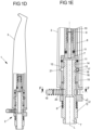
- the Figure 1D shows the adapter arrangement 1 of the Figure 1A in its second operating state, namely in its locking position, in which the hollow body instrument 3 is firmly connected to the adapter 2. This is shown in the enlarged detail view of the Figure 1E to be recognized even more clearly.
- the hollow body instrument 3 In order to move the adapter 2 from the release position to the locking position, the hollow body instrument 3 is pressed onto the outer part 4 against the spring force applied by the compression spring 6. This causes the outer part 4 to move downward, while the position of the inner part 5 does not change. This results in a relative movement between the outer part 4 and the inner part 5. As a result, the recess on the inner part 5 and the opening 13 (and thus the ball 18 located in the opening 13) are no longer aligned with one another. Instead, the outer contour of the inner part 5 presses the ball 18 radially outwards. However, since the second opening 17 prevents the ball 18 from passing completely through, it can only protrude a small area beyond the outer envelope of the outer part wall 12 of the outer part 4 of the adapter 2.
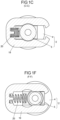
- This locking position is shown in the cross-section of the locking clip 19 along the line F in the Figure 1F shown in detail. Due to the contouring of the locking clip 19, a relative movement between the outer part 4 and the inner part 5 of the adapter 2 is prevented in the locking position of the locking clip 19. Rather, such a relative movement between the outer part 4 and the inner part 5 is only possible again when the locking clip 19 is transferred to the unlocking position, which is shown in the Figure 1C is shown.
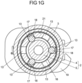
- openings 13 can be seen from the line GG in the Figure 1B reproduced cross-sectional view of the Figure 1G visible.
- Two openings 13 are located opposite each other and are produced in a single manufacturing step. For this purpose, a bore is drilled which extends completely through a first of the opposing openings 13, but which does not extend completely to the outside (towards the radially inner groove 21 of the hollow body instrument 3) in the second of the opposing openings. Rather, the incomplete bore in the second of the opposing openings 13 forms the second opening 17, which has an opening diameter which is slightly smaller than the diameter of the ball 18.
- the ball 18 can be partially pressed radially outwards through the second opening 17 in its detent position and engage in the groove 21 of the hollow body instrument 3. However, it cannot fall out of the opening 13 through the second opening 17 if no hollow body instrument 3 is connected to the adapter 2.
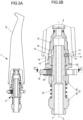
- the Figure 2A shows a longitudinal sectional view through a second embodiment of an adapter arrangement 1 with an adapter 2 and a hollow body instrument 3.
- the hollow body instrument 3 has a different outer and inner geometry than the hollow body instrument 3 of the embodiment shown in the Figures 1A to 1F is shown.
- a hollow body instrument 3 designed in this way can also be easily connected to the adapter 2.
- the functional principle of the connection is identical to the functional principle that applies to the adapter arrangement 1 of the Figures 1A to 1F In this respect, reference is made to the relevant explanations above.
- the Figure 2B shows an enlarged detailed view of the longitudinal section of the Figure 2A . It is noticeable that the Figures 2A and 2B
- the adapter 2 shown does not have a silicone mold or a retaining sleeve. Rather, the connection between the adapter channel 7 of the adapter 2 and the instrument channel 8 of the hollow-body instrument 3 is made without a corresponding silicone mold, but still in a fluid-tight manner.
- the adapter 2 is in its release position, in which the ball 18 projects into a recess on the outside of the inner part 5 of the adapter 2.
- the ball 18 does not exert any locking force on the hollow body instrument 3, so that it can be easily removed from the adapter 2.
- the locking clip 19 is - as in the Figure 1B illustrated operating state of the adapter 2 there - in its unlocked position, so that the outer part 4 and the inner part 5 of the adapter 2 can move against each other.
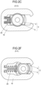
- FIG. 2C A corresponding cross-sectional view along line C of the Figure 2B is in the Figure 2C shown.
- the Figure 2C is almost identical to the Figure 1C , since the cross-sections of the adapters 2 differ only slightly from each other in this area.
- the locking clip 19 must be moved in a direction that runs perpendicular to the longitudinal axis L of the adapter 2 in order to be transferred from its unlocking position to its locking position.
- the force that must be applied to release the hollow body instrument 3 therefore depends significantly on the spring force of the second spring 20. However, it is not proportional to the holding force applied by the adapter 2 via the locking device against the hollow body instrument 3. As a result, the release force is decoupled from the holding force, which on the one hand enables a particularly strong connection between the adapter 2 and the hollow body instrument 3, but on the other hand also allows particularly simple operation of the adapter 2.
- FIG. 2D is the adapter arrangement 1 of the Figure 2A in its second operating state, namely in the locking position of the adapter 2, in which the hollow body instrument 3 is firmly connected to the adapter 2. This is shown in the enlarged detail view of the Figure 2E to see in more detail.
- the contour of the inner part 5 presses the ball 18 radially outwards so that it protrudes partially through the second opening 17 into the groove 21 of the hollow body instrument 3 and thus ensures a positive connection between the hollow body instrument 3 and the adapter 2.
- the locking clip 19 is again in its locking position, which is shown in the cross-sectional view of the Figure 2F along line F of the Figure 2D is shown. In this locking position, the locking clip 19 prevents further relative movement between the inner part 5 and the outer part 4 of the adapter 2.
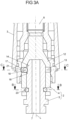
- the Figure 3A shows a detailed representation of a further embodiment of an adapter arrangement 1 with an adapter 2 and a hollow body instrument 3 coupled thereto.
- the adapter 2 has an outer part 4 and an inner part 5.
- a locking device is provided which has a ball 18 which is movable in an opening 13 and which, in its locking position, fixes the hollow body instrument 3 to the adapter 2 and in its Release position allows the hollow body instrument 3 to be plugged onto the adapter 2 or allows the hollow body instrument 3 to be released from the adapter 2.
- the locking device is shown in its release position.
- the ball 18 projects beyond the inner opening 16 of the aperture 13 into a recess between the inner side 14 of the outer part wall 12 and an outer side of the inner part 5.
- the ball could also project into the radially inner groove 21 in the hollow-body instrument 3, but would not perform a locking function there, since it could move freely within the aperture 13 toward the inner part 5 at any time.
- Figure 3B a cross-sectional view along line B in the Figure 3A
- Figures 3C and 3D a cross-sectional view along line C of the Figure 3A in two different positions of the adapter arrangement 1.
- the locking mechanism of the adapter 2 can be returned to the release position by rotating the wire bracket 23 90° counterclockwise.
- the recess on the outside of the inner part 5 of the adapter 2 is then aligned with the opening 13 again, so that the ball 18 is no longer pushed out of the second opening 17, but can protrude into the recess. Consequently, the ball 18 no longer exerts a locking force on the hollow-body instrument 3.
- the hollow body instrument 3 has the groove 21 (radially inward with respect to the hollow body instrument) in the area of the ball 18, the ball 18 also engages in this groove 21 in the locking position and ensures a positive connection between the hollow body instrument 3 and the adapter 2. This makes it possible for the hollow body instrument 3 to fit even more securely on the adapter 2 than if only a locking force imparted by the ball 18 is used to secure the hollow body instrument 3.
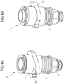
- FIGS. 4A and 4B show a further embodiment of an adapter 2, wherein the adapter 2 in the Figure 4A shown in its decoupled position (release position), while in the Figure 4B in its coupled position (locking position), in which a hollow body instrument 3 is fixed to the adapter 2.
- the adapter 2 comprises an outer part 4 and an inner part 5, which are laterally movable relative to each other. Furthermore, a locking clip 19 is provided, which in its Figure 4A illustrated unlocking position allows a relative movement between the outer part 4 and the inner part 5 of the adapter 2, while such a movement in the locking position of the locking clip 19, which is shown in the Figure 4B shown, is no longer possible. This is ensured by the specific contouring of the locking clip 19.
- the adapter 2 By a first spring 6, the adapter 2 is pre-tensioned into its uncoupled position, in which a locking device of the adapter 2 is in its release position. This is shown in the Figure 4A can be seen. If the outer part 4 is pressed down relative to the inner part 5 against the spring force applied by the first spring 6, the adapter 2 is transferred into its coupled position, in which the locking device of the adapter 2 is in its locking position.
- the Figure 4C shows the adapter 2 of the Figure 4A in its decoupled position in a side view. It can be seen that the second spring 20, which preloads the locking clip 19 into its locking position, is compressed in the decoupled position of the adapter 2. This means that a force opposite to that exerted by the second spring 20 applied spring force to compress the spring 20 and to transfer the locking clip 19 from its locking position to its unlocking position, in which a lateral movement between the outer part 4 and the inner part 5 of the adapter 2 along the longitudinal axis L is possible.
- a hollow body instrument 3 placed on the adapter 2 can also be seen in detail.
- the Figure 4D shows a longitudinal section through the adapter 2 of the Figure 4C In this longitudinal section, the locking device of the adapter 2 is visible, which - similar to the locking device of the Figures 1A to 1F and 2A to 2F has an opening 13. However, not only a ball 18 is arranged in the opening 13. Rather, the ball 18 is surrounded by a snap ring 24, which serves as a movement-limiting device. Thus, in this embodiment, it is not necessary for the second opening 17, which is formed on the radially outer side of the opening 13, to have a diameter that is smaller than the diameter of the ball 18. Rather, the snap ring 24 ensures that the ball 18 cannot leave the opening 13 to the outside through the second opening 17.
- the ball 18 it is still possible for the ball 18 to at least partially exit the opening 13 through the first opening 16 to a recess formed on the outside of the inner part 5.
- the space available to the ball 18 and the snap ring 24 is larger than the space required by these two elements.
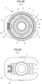
- the Figure 4E shows a cross-sectional view through the adapter 2 of the Figure 4C along the line marked E.
- the Figure 4E the adapter 2 at the level of the locking device.
- the locking device has four openings 13 arranged evenly along the circumference of the outer part 4, in each of which a ball 18 is arranged. While the balls 18 can each protrude through the inner opening 16 from the outer part wall 12 into a recess in the outside of the inner part 5, their movement radially outward is limited by the snap ring 24. This prevents the balls 18 from falling out of the adapter 2.
- the Figure 4F shows a cross-sectional view through the adapter 2 along the line marked F in the Figure 4C .
- This cross-sectional view shows the adapter 2 at the level of the locking clip 19.
- the locking clip 19 is in its unlocking position, in which a relative movement between the outer part 4 and the inner part 5 of the adapter 2 is possible, since the locking clip 19 has a corresponding circular recess in its center.
- the Figure 4G shows a side view of the adapter 2 of the Figure 4B , i.e. the adapter 2 in its coupled position.
- the hollow body instrument 3 is fixed to the adapter 2.
- the locking device of the adapter 2 is in its locking position.
- the locking device has been moved from the release position, which is in the Figures 4A, 4B and 4C shown, into the locking position of the Figure 4G by moving the outer part 4 and the inner part 5 of the adapter 2 relative to each other along the longitudinal axis L. This movement compresses the first spring 6.
- the Figure 4I shows a cross-sectional view along the line marked I in the Figure 4G , i.e. at the level of the locking device of adapter 2.
- the locking device is in its locking position.
- the balls 18 are pressed radially further outwards by the inner part 5 of the adapter 2 and thus expand the snap ring 24.
- the snap ring 24 thus exerts a locking force on the hollow body instrument 3 and engages in a groove 21 formed in the hollow body instrument 3, thus resulting in a positive connection between the adapter 2 and the hollow body instrument 3.
- the adapter 2 If the adapter 2 is to release the hollow body instrument 3 again, a force opposite to the spring force applied by the second spring 20 must first be exerted in order to return the locking clip 19 to its unlocked position, in which it allows a relative lateral movement of the inner part 5 relative to the outer part 4 of the adapter 2. Then, the locking device of the adapter 2 is moved from its locking position to its release position so that the hollow body instrument 3 can be removed from the adapter 2.
- the Figure 5 shows a longitudinal section through another embodiment of an adapter 2, which is very similar to that shown in the Figure 4H illustrated embodiment. In this respect, reference is made to the above explanations.
- the adapter 2 is shown in its coupled position, i.e., in a position in which the locking device of the adapter 2 is in its locking position.
- the adapter 2 of the Figure 5 not a snap ring with a circular cross-section, but a snap ring 24 with a specially designed contour.
- the snap ring 24 has a flat inner side oriented towards the ball 18, while on its outer side it has a nose 25 which is shaped such that it can engage in the groove 21 of the hollow body instrument 3.
- the snap ring 24 can take on any shape suitable for achieving a secure connection between the adapter 2 and the hollow body instrument 3.
- the Figure 5 The design of the snap ring 24 shown is therefore only to be understood as an example.
- the contouring of the outer side of the inner part 5 of the adapter 2 can be designed as desired in order to influence the movement of the ball 18 from the release position to the locking position of the locking device according to the respective requirements.
- the ball 18 in the adapter 2 of the Figure 5 in the locking position more radial outwards than in the case of the Figure 4H shown adapter 2.
- the snap ring 24 of the adapter 2 of the Figure 5 a slightly smaller radial diameter than the snap ring 24 of the adapter 2 of the Figure 4H This allows the adapter 2 to be individually adapted to the hollow body instruments 3 to be contacted, which opens up numerous application possibilities for the adapter 2.
Landscapes
- Health & Medical Sciences (AREA)
- Life Sciences & Earth Sciences (AREA)
- General Health & Medical Sciences (AREA)
- Animal Behavior & Ethology (AREA)
- Surgery (AREA)
- Oral & Maxillofacial Surgery (AREA)
- Veterinary Medicine (AREA)
- Public Health (AREA)
- Medical Informatics (AREA)
- Pathology (AREA)
- Molecular Biology (AREA)
- Heart & Thoracic Surgery (AREA)
- Nuclear Medicine, Radiotherapy & Molecular Imaging (AREA)
- Biomedical Technology (AREA)
- Engineering & Computer Science (AREA)
- Dentistry (AREA)
- Epidemiology (AREA)
- Quick-Acting Or Multi-Walled Pipe Joints (AREA)
Claims (15)
- Adaptateur (2) pour relier un objet à corps creux (3) à un appareil pour le rinçage intérieur d'objets à corps creux,l'adaptateur (2) présentant une partie intérieure (5) et une partie extérieure (4) entourant la partie intérieure (5) au moins par sections,la partie intérieure (5) et la partie extérieure (4) étant mobiles l'une par rapport à l'autre et s'étendant le long d'un axe d'extension longitudinal (L),la partie extérieure (4) présentant une paroi de partie extérieure (12) avec au moins un dispositif d'encliquetage,caractérisé en ceque le dispositif d'encliquetage comprend un passage (13) dans la paroi de partie extérieure (12), un corps (18) monté mobile dans le passage (13) et un dispositif de limitation de mouvement (17, 24),le passage présentant une première ouverture (16) dans une face intérieure (14) de la paroi de partie extérieure (12) orientée vers la partie intérieure (5) et une deuxième ouverture (17) dans une face extérieure (15) de la paroi de partie extérieure (12), une direction radiale s'étendant de la première ouverture (16) à la deuxième ouverture (17),le dispositif de limitation de mouvement (17, 24) limitant un mouvement du corps (18) s'étendant dans la direction radiale vers la deuxième ouverture (17) et empêche le corps (18) de passer complètement à travers la deuxième ouverture (17) vers l'extérieur,la première ouverture (16) présentant un diamètre qui est supérieur à un diamètre de section transversale du corps (18),le dispositif d'encliquetage étant réglable entre une position de libération et une position d'encliquetage par un mouvement effectué au moyen d'un mouvement relatif entre la partie extérieure (4) et la partie intérieure (5),le corps (18) étant disposé radialement plus à l'extérieur dans le passage (13) dans la position d'encliquetage que dans la position de libération,un côté extérieur du dispositif d'encliquetage ne faisant pas saillie au-delà d'une enveloppe extérieure de la paroi de partie extérieure (12) dans la position de libération, mais fait saillie au-delà de l'enveloppe extérieure de la paroi de partie extérieure (12) dans la position d'encliquetage.
- Adaptateur selon la revendication 1, caractérisé en ce que le dispositif de limitation de mouvement est formé par un jonc d'arrêt (24) qui est agencé dans le passage (13) autour de l'extérieur du corps (18) dans la direction radiale.
- Adaptateur selon la revendication 2, caractérisé en ce que la paroi de partie extérieure (12) présente, dans la zone du dispositif d'encliquetage, une épaisseur de paroi qui est inférieure à une extension du corps (18) et du jonc d'arrêt (24) dans la direction radiale.
- Adaptateur selon la revendication 1, caractérisé en ce que le dispositif de limitation de mouvement est formé par un diamètre de la deuxième ouverture (17) qui est inférieur au diamètre de la section transversale du corps (18).
- Adaptateur selon la revendication 4, caractérisé en ce que la paroi de partie extérieure (12) présente, dans la zone du dispositif d'encliquetage, une épaisseur de paroi qui est inférieure à une extension du corps (18) dans la direction radiale.
- Adaptateur selon l'une quelconque des revendications précédentes, caractérisé en ce que l'adaptateur (2) comprend un élément de verrouillage (19) qui est mobile par rapport à la partie extérieure (4) et à la partie intérieure (5) entre une position de déverrouillage et une position de verrouillage, l'élément de verrouillage (19) dans la position de déverrouillage permettant le mouvement relatif entre la partie extérieure (4) et la partie intérieure (5) et dans la position de verrouillage empêchant ce mouvement relatif.
- Adaptateur selon la revendication 6, caractérisé en ce que l'élément de verrouillage (19) est mobile transversalement à l'axe d'extension longitudinal (L) entre la position de déverrouillage et la position de verrouillage.
- Adaptateur selon la revendication 6 ou 7, caractérisé en ce que l'élément de verrouillage (19) est précontraint dans la position de verrouillage par un premier élément de précontrainte (20).
- Adaptateur selon l'une quelconque des revendications précédentes, caractérisé en ce que la partie intérieure (5) présente un rétrécissement de section transversale orienté vers la partie extérieure (4) qui, en position de libération, est aligné avec le passage (13), de sorte que le corps (18) peut pénétrer dans le rétrécissement de section transversale.
- Adaptateur selon la revendication 9, caractérisé en ce que le rétrécissement de section transversale n'est pas aligné avec le passage (13) dans la position d'encliquetage.
- Adaptateur selon l'une quelconque des revendications précédentes, caractérisé en ce que le corps (18) est monté sans précontrainte dans le passage (13) dans la position de libération.
- Adaptateur selon l'une quelconque des revendications précédentes, caractérisé en ce que exactement un corps (18) est monté dans le passage (13).
- Adaptateur selon l'une quelconque des revendications précédentes, caractérisé en ce que l'adaptateur (2) comprend au moins deux dispositifs d'encliquetage qui sont agencés dans la partie extérieure (4), en particulier uniformément le long d'une direction circonférentielle de la partie extérieure (4).
- Ensemble adaptateur (1), comprenant un adaptateur (2) selon l'une quelconque des revendications précédentes et un objet à corps creux (3) agencé sur un côté extérieur (15) de la partie extérieure (4), qui est relié de manière amovible à l'adaptateur (2) dans la position de libération du dispositif d'encliquetage et qui est relié à l'adaptateur (2) dans la position d'encliquetage du dispositif d'encliquetage i) par complémentarité de formes ou ii) par complémentarité de formes et de forces ou iii) par complémentarité de forces.
- Procédé pour relier un objet à corps creux (3) à un appareil pour le rinçage intérieur d'objets à corps creux et pour détacher l'objet à corps creux de l'appareil, caractérisé par les étapes suivantes :a) emboîtement d'un objet à corps creux (3) sur une face extérieure (15) d'un adaptateur (2) selon l'une quelconque des revendications 1 à 13 ;b) un mouvement relatif de la partie extérieure (4) et de la partie intérieure (5) de l'adaptateur (2) l'une par rapport à l'autre, afin de faire passer le dispositif d'encliquetage de la position de libération à la position d'encliquetage ;c) un mouvement relatif de la partie extérieure (4) et de la partie intérieure (5) de l'adaptateur (2) l'une par rapport à l'autre, afin de faire passer le dispositif d'encliquetage de la position d'encliquetage à la position de libération ; etd) enlever l'objet à corps creux (3) du côté extérieur (15) de l'adaptateur (2).
Priority Applications (1)
| Application Number | Priority Date | Filing Date | Title |
|---|---|---|---|
| EP23166186.9A EP4438063B1 (fr) | 2023-03-31 | 2023-03-31 | Adaptateur pour relier un objet à corps creux à un appareil pour le rinçage intérieur d'objets à corps creux |
Applications Claiming Priority (1)
| Application Number | Priority Date | Filing Date | Title |
|---|---|---|---|
| EP23166186.9A EP4438063B1 (fr) | 2023-03-31 | 2023-03-31 | Adaptateur pour relier un objet à corps creux à un appareil pour le rinçage intérieur d'objets à corps creux |
Publications (2)
| Publication Number | Publication Date |
|---|---|
| EP4438063A1 EP4438063A1 (fr) | 2024-10-02 |
| EP4438063B1 true EP4438063B1 (fr) | 2025-05-28 |
Family
ID=85800654
Family Applications (1)
| Application Number | Title | Priority Date | Filing Date |
|---|---|---|---|
| EP23166186.9A Active EP4438063B1 (fr) | 2023-03-31 | 2023-03-31 | Adaptateur pour relier un objet à corps creux à un appareil pour le rinçage intérieur d'objets à corps creux |
Country Status (1)
| Country | Link |
|---|---|
| EP (1) | EP4438063B1 (fr) |
Citations (1)
| Publication number | Priority date | Publication date | Assignee | Title |
|---|---|---|---|---|
| EP3248571A1 (fr) * | 2016-05-25 | 2017-11-29 | Miele & Cie. KG | Adaptateur de raccordement |
Family Cites Families (8)
| Publication number | Priority date | Publication date | Assignee | Title |
|---|---|---|---|---|
| DE4323816C2 (de) | 1993-07-15 | 1996-02-08 | Siemens Ag | Verfahren und Vorrichtung zur Intensivreinigung von ärztlichen, insbesondere zahnärztlichen, Gegenständen |
| DE29624425U1 (de) | 1996-07-04 | 2003-06-05 | Miele & Cie. GmbH & Co., 33332 Gütersloh | Spülvorrichtung zur Innendurchspülung und Halterung zahnärztlicher Hand- und Winkelstücke |
| DE102008023458B3 (de) * | 2008-05-14 | 2009-08-13 | Efs-Eberle Feinwerktechnische Systeme Gmbh & Co. Kg | Handstückreinigungsadapter |
| DE102014107136A1 (de) | 2014-05-21 | 2015-11-26 | Miele & Cie. Kg | Vorrichtung zur Innendurchspülung von dentalem Spülgut |
| DE102014111237B4 (de) | 2014-08-07 | 2016-09-22 | Miele & Cie. Kg | Spülvorrichtung zur Innendurchspülung von dentalem Spülgut |
| DE102016102907B4 (de) | 2015-03-03 | 2019-05-02 | Kögel GmbH | Haltevorrichtung für einen Kopf eines medizinischen Instruments und Verfahren zum Reinigen und/oder Desinfizieren eines derartigen Kopfes |
| DE102019209045A1 (de) * | 2019-06-21 | 2020-12-24 | Eberle Gmbh & Co. Kg | Reinigungsadapter für medizinische Instrumente |
| DE102021119351A1 (de) | 2020-08-11 | 2022-02-17 | Miele & Cie. Kg | Adaptionsvorrichtung zum Aufnehmen von medizinischem Reinigungsgut, Spülkorb und Reinigungsgerät |
-
2023
- 2023-03-31 EP EP23166186.9A patent/EP4438063B1/fr active Active
Patent Citations (1)
| Publication number | Priority date | Publication date | Assignee | Title |
|---|---|---|---|---|
| EP3248571A1 (fr) * | 2016-05-25 | 2017-11-29 | Miele & Cie. KG | Adaptateur de raccordement |
Also Published As
| Publication number | Publication date |
|---|---|
| EP4438063A1 (fr) | 2024-10-02 |
Similar Documents
| Publication | Publication Date | Title |
|---|---|---|
| DE10357105B3 (de) | Medizinisches Instrument | |
| WO2005064222A1 (fr) | Raccord a emboitement pour conduites de fluide | |
| DE60305236T2 (de) | Verbindungsvorrichtung zur Verbindung von zwei Rohren | |
| DE102005036808B4 (de) | Druckmittelbetätigte Dockingvorrichtung | |
| EP2411190A1 (fr) | Appareil fluidotechnique, en particulier dispositif à griffe | |
| EP1778065B1 (fr) | Raccord permettant de raccorder un flexible d'aspirateur a un tuyau | |
| EP3631100B1 (fr) | Valve de plomberie comprenant une membrane | |
| DE102016124805B4 (de) | Membranventil | |
| DE10229650A1 (de) | Medizinisches oder dentalmedizinisches Handstück mit einem hinteren und einem vorderen Handstückabschnitt | |
| EP4438063B1 (fr) | Adaptateur pour relier un objet à corps creux à un appareil pour le rinçage intérieur d'objets à corps creux | |
| EP4076869A1 (fr) | Élément de préhension à pression négative et dispositif de préhension à pression négative | |
| EP0670149A1 (fr) | Pièce à main droite motorisée, en particulier pour des fins médicales, de préférence pour un laboratoire médical ou dentaire | |
| EP1506833A1 (fr) | Connection de buse laser | |
| EP1709931B1 (fr) | Organe moteur, en particulier pièce à main dentaire avec un accouplement détachable pour un porte-outil | |
| EP0029860A1 (fr) | Instrument à main dentaire | |
| DE102020103984B4 (de) | Spannvorrichtung | |
| EP0451739A2 (fr) | Pièce de raccord | |
| EP2918354A1 (fr) | Presse destinée à comprimer axialement des pièces à usiner | |
| EP1801485B1 (fr) | Raccord multiple pour tubes ou tuyaux | |
| EP0711946B1 (fr) | Accouplement enfichable pour tuyaux | |
| DE10114978B4 (de) | Autoklav-Sterilisationsanlage | |
| DE20300666U1 (de) | Anschlussvorrichtung für Fluidleitungen | |
| DE102021119351A1 (de) | Adaptionsvorrichtung zum Aufnehmen von medizinischem Reinigungsgut, Spülkorb und Reinigungsgerät | |
| DE3715911C2 (de) | Vorrichtung zur Verbindung einer schlauchspitze mit einem Schlauchende eines extrakorporalen medizinischen Versorgungssystems | |
| DE102006016883A1 (de) | Verfahren zum Befestigen eines Werkzeugs in einem Werkzeugfutter und Werkzeugfutter |
Legal Events
| Date | Code | Title | Description |
|---|---|---|---|
| PUAI | Public reference made under article 153(3) epc to a published international application that has entered the european phase |
Free format text: ORIGINAL CODE: 0009012 |
|
| STAA | Information on the status of an ep patent application or granted ep patent |
Free format text: STATUS: REQUEST FOR EXAMINATION WAS MADE |
|
| 17P | Request for examination filed |
Effective date: 20231004 |
|
| AK | Designated contracting states |
Kind code of ref document: A1 Designated state(s): AL AT BE BG CH CY CZ DE DK EE ES FI FR GB GR HR HU IE IS IT LI LT LU LV MC ME MK MT NL NO PL PT RO RS SE SI SK SM TR |
|
| GRAP | Despatch of communication of intention to grant a patent |
Free format text: ORIGINAL CODE: EPIDOSNIGR1 |
|
| STAA | Information on the status of an ep patent application or granted ep patent |
Free format text: STATUS: GRANT OF PATENT IS INTENDED |
|
| INTG | Intention to grant announced |
Effective date: 20250102 |
|
| RIC1 | Information provided on ipc code assigned before grant |
Ipc: A61C 1/12 20060101ALN20241216BHEP Ipc: A61C 1/10 20060101ALN20241216BHEP Ipc: A61M 39/16 20060101ALI20241216BHEP Ipc: A61B 90/70 20160101ALI20241216BHEP Ipc: A61L 2/26 20060101ALI20241216BHEP Ipc: A61C 19/00 20060101ALI20241216BHEP Ipc: A61L 2/00 20060101AFI20241216BHEP |
|
| GRAS | Grant fee paid |
Free format text: ORIGINAL CODE: EPIDOSNIGR3 |
|
| GRAA | (expected) grant |
Free format text: ORIGINAL CODE: 0009210 |
|
| STAA | Information on the status of an ep patent application or granted ep patent |
Free format text: STATUS: THE PATENT HAS BEEN GRANTED |
|
| P01 | Opt-out of the competence of the unified patent court (upc) registered |
Free format text: CASE NUMBER: APP_15001/2025 Effective date: 20250327 |
|
| AK | Designated contracting states |
Kind code of ref document: B1 Designated state(s): AL AT BE BG CH CY CZ DE DK EE ES FI FR GB GR HR HU IE IS IT LI LT LU LV MC ME MK MT NL NO PL PT RO RS SE SI SK SM TR |
|
| REG | Reference to a national code |
Ref country code: GB Ref legal event code: FG4D Free format text: NOT ENGLISH |
|
| REG | Reference to a national code |
Ref country code: CH Ref legal event code: EP |
|
| REG | Reference to a national code |
Ref country code: DE Ref legal event code: R096 Ref document number: 502023001045 Country of ref document: DE |
|
| REG | Reference to a national code |
Ref country code: IE Ref legal event code: FG4D Free format text: LANGUAGE OF EP DOCUMENT: GERMAN |
|
| REG | Reference to a national code |
Ref country code: NL Ref legal event code: MP Effective date: 20250528 |
|
| PG25 | Lapsed in a contracting state [announced via postgrant information from national office to epo] |
Ref country code: FI Free format text: LAPSE BECAUSE OF FAILURE TO SUBMIT A TRANSLATION OF THE DESCRIPTION OR TO PAY THE FEE WITHIN THE PRESCRIBED TIME-LIMIT Effective date: 20250528 Ref country code: ES Free format text: LAPSE BECAUSE OF FAILURE TO SUBMIT A TRANSLATION OF THE DESCRIPTION OR TO PAY THE FEE WITHIN THE PRESCRIBED TIME-LIMIT Effective date: 20250528 |
|
| REG | Reference to a national code |
Ref country code: LT Ref legal event code: MG9D |
|
| PG25 | Lapsed in a contracting state [announced via postgrant information from national office to epo] |
Ref country code: GR Free format text: LAPSE BECAUSE OF FAILURE TO SUBMIT A TRANSLATION OF THE DESCRIPTION OR TO PAY THE FEE WITHIN THE PRESCRIBED TIME-LIMIT Effective date: 20250829 Ref country code: NO Free format text: LAPSE BECAUSE OF FAILURE TO SUBMIT A TRANSLATION OF THE DESCRIPTION OR TO PAY THE FEE WITHIN THE PRESCRIBED TIME-LIMIT Effective date: 20250828 |
|
| PG25 | Lapsed in a contracting state [announced via postgrant information from national office to epo] |
Ref country code: PL Free format text: LAPSE BECAUSE OF FAILURE TO SUBMIT A TRANSLATION OF THE DESCRIPTION OR TO PAY THE FEE WITHIN THE PRESCRIBED TIME-LIMIT Effective date: 20250528 Ref country code: NL Free format text: LAPSE BECAUSE OF FAILURE TO SUBMIT A TRANSLATION OF THE DESCRIPTION OR TO PAY THE FEE WITHIN THE PRESCRIBED TIME-LIMIT Effective date: 20250528 |
|
| PG25 | Lapsed in a contracting state [announced via postgrant information from national office to epo] |
Ref country code: BG Free format text: LAPSE BECAUSE OF FAILURE TO SUBMIT A TRANSLATION OF THE DESCRIPTION OR TO PAY THE FEE WITHIN THE PRESCRIBED TIME-LIMIT Effective date: 20250528 |
|
| PG25 | Lapsed in a contracting state [announced via postgrant information from national office to epo] |
Ref country code: HR Free format text: LAPSE BECAUSE OF FAILURE TO SUBMIT A TRANSLATION OF THE DESCRIPTION OR TO PAY THE FEE WITHIN THE PRESCRIBED TIME-LIMIT Effective date: 20250528 |
|
| PG25 | Lapsed in a contracting state [announced via postgrant information from national office to epo] |
Ref country code: RS Free format text: LAPSE BECAUSE OF FAILURE TO SUBMIT A TRANSLATION OF THE DESCRIPTION OR TO PAY THE FEE WITHIN THE PRESCRIBED TIME-LIMIT Effective date: 20250828 |
|
| PG25 | Lapsed in a contracting state [announced via postgrant information from national office to epo] |
Ref country code: IS Free format text: LAPSE BECAUSE OF FAILURE TO SUBMIT A TRANSLATION OF THE DESCRIPTION OR TO PAY THE FEE WITHIN THE PRESCRIBED TIME-LIMIT Effective date: 20250928 |
|
| PG25 | Lapsed in a contracting state [announced via postgrant information from national office to epo] |
Ref country code: LV Free format text: LAPSE BECAUSE OF FAILURE TO SUBMIT A TRANSLATION OF THE DESCRIPTION OR TO PAY THE FEE WITHIN THE PRESCRIBED TIME-LIMIT Effective date: 20250528 |
|
| PG25 | Lapsed in a contracting state [announced via postgrant information from national office to epo] |
Ref country code: SM Free format text: LAPSE BECAUSE OF FAILURE TO SUBMIT A TRANSLATION OF THE DESCRIPTION OR TO PAY THE FEE WITHIN THE PRESCRIBED TIME-LIMIT Effective date: 20250528 Ref country code: DK Free format text: LAPSE BECAUSE OF FAILURE TO SUBMIT A TRANSLATION OF THE DESCRIPTION OR TO PAY THE FEE WITHIN THE PRESCRIBED TIME-LIMIT Effective date: 20250528 |
|
| PG25 | Lapsed in a contracting state [announced via postgrant information from national office to epo] |
Ref country code: CZ Free format text: LAPSE BECAUSE OF FAILURE TO SUBMIT A TRANSLATION OF THE DESCRIPTION OR TO PAY THE FEE WITHIN THE PRESCRIBED TIME-LIMIT Effective date: 20250528 |
|
| PG25 | Lapsed in a contracting state [announced via postgrant information from national office to epo] |
Ref country code: EE Free format text: LAPSE BECAUSE OF FAILURE TO SUBMIT A TRANSLATION OF THE DESCRIPTION OR TO PAY THE FEE WITHIN THE PRESCRIBED TIME-LIMIT Effective date: 20250528 |
|
| PG25 | Lapsed in a contracting state [announced via postgrant information from national office to epo] |
Ref country code: SK Free format text: LAPSE BECAUSE OF FAILURE TO SUBMIT A TRANSLATION OF THE DESCRIPTION OR TO PAY THE FEE WITHIN THE PRESCRIBED TIME-LIMIT Effective date: 20250528 |
|
| REG | Reference to a national code |
Ref country code: DE Ref legal event code: R097 Ref document number: 502023001045 Country of ref document: DE |
|
| REG | Reference to a national code |
Ref country code: CH Ref legal event code: U11 Free format text: ST27 STATUS EVENT CODE: U-0-0-U10-U11 (AS PROVIDED BY THE NATIONAL OFFICE) Effective date: 20260401 |
|
| PLBE | No opposition filed within time limit |
Free format text: ORIGINAL CODE: 0009261 |
|
| STAA | Information on the status of an ep patent application or granted ep patent |
Free format text: STATUS: NO OPPOSITION FILED WITHIN TIME LIMIT |
|
| REG | Reference to a national code |
Ref country code: CH Ref legal event code: L10 Free format text: ST27 STATUS EVENT CODE: U-0-0-L10-L00 (AS PROVIDED BY THE NATIONAL OFFICE) Effective date: 20260409 |
|
| PGFP | Annual fee paid to national office [announced via postgrant information from national office to epo] |
Ref country code: DE Payment date: 20260213 Year of fee payment: 4 |
|
| PGFP | Annual fee paid to national office [announced via postgrant information from national office to epo] |
Ref country code: FR Payment date: 20260324 Year of fee payment: 4 |