EP4438152A1 - Filter - Google Patents
Filter Download PDFInfo
- Publication number
- EP4438152A1 EP4438152A1 EP23166254.5A EP23166254A EP4438152A1 EP 4438152 A1 EP4438152 A1 EP 4438152A1 EP 23166254 A EP23166254 A EP 23166254A EP 4438152 A1 EP4438152 A1 EP 4438152A1
- Authority
- EP
- European Patent Office
- Prior art keywords
- filter
- filter element
- scrubbing means
- scrubbing
- filter according
- Prior art date
- Legal status (The legal status is an assumption and is not a legal conclusion. Google has not performed a legal analysis and makes no representation as to the accuracy of the status listed.)
- Granted
Links
Images

Classifications
-
- B—PERFORMING OPERATIONS; TRANSPORTING
- B01—PHYSICAL OR CHEMICAL PROCESSES OR APPARATUS IN GENERAL
- B01D—SEPARATION
- B01D29/00—Filters with filtering elements stationary during filtration, e.g. pressure or suction filters, not covered by groups B01D24/00 - B01D27/00; Filtering elements therefor
- B01D29/62—Regenerating the filter material in the filter
- B01D29/64—Regenerating the filter material in the filter by scrapers, brushes, nozzles, or the like, acting on the cake side of the filtering element
- B01D29/6407—Regenerating the filter material in the filter by scrapers, brushes, nozzles, or the like, acting on the cake side of the filtering element brushes
-
- B—PERFORMING OPERATIONS; TRANSPORTING
- B01—PHYSICAL OR CHEMICAL PROCESSES OR APPARATUS IN GENERAL
- B01D—SEPARATION
- B01D29/00—Filters with filtering elements stationary during filtration, e.g. pressure or suction filters, not covered by groups B01D24/00 - B01D27/00; Filtering elements therefor
- B01D29/62—Regenerating the filter material in the filter
- B01D29/64—Regenerating the filter material in the filter by scrapers, brushes, nozzles, or the like, acting on the cake side of the filtering element
- B01D29/6469—Regenerating the filter material in the filter by scrapers, brushes, nozzles, or the like, acting on the cake side of the filtering element scrapers
-
- B—PERFORMING OPERATIONS; TRANSPORTING
- B01—PHYSICAL OR CHEMICAL PROCESSES OR APPARATUS IN GENERAL
- B01D—SEPARATION
- B01D33/00—Filters with filtering elements which move during the filtering operation
- B01D33/44—Regenerating the filter material in the filter
- B01D33/46—Regenerating the filter material in the filter by scrapers, brushes nozzles or the like acting on the cake-side of the filtering element
Definitions
- Embodiments relate to filters for liquid purification, for example, for removing mechanical impurities. More specifically, the invention is directed to pre- or postfilters to be used in industrial systems, for example, washing system, or to household use.
- filters become clogged with therein impurities from the main equipment and break. It is necessary either to change the cartridge, or to flush it. From the prior art filters are known with backwashing and equipped with outer and inner mechanical scrubbing means.
- the filter for oil filtration comprises a body with filter elements, outer scrubbing means with a brush, a reduction gear unit and an electric motor.
- the filter for oil filtration comprises a body with filter elements, outer scrubbing means with a brush, a reduction gear unit and an electric motor.
- In the lower part of the body there is an inlet for contaminated oil.
- In the upper part of the body there is an outlet for purified oil.
- Lower part of the body has a conical section - a sediment chamber with a dismountable drain plug.
- Vertical six-filter elements are made as a number of paper disks attached to each other with a spring.
- the brush is made to scrub an outer surface of the filter elements.
- the filter elements and the brush rotate by means of the reduction gear unit, which is connected to said electric motor.
- the filter from the patent US2354150 operates as follows. Contaminated oil under pressure is supplied into the filter body, purifies while flowing through the filter elements, and exits for reuse. Contaminants, which are separated during filtration process, partly flow into the sediment chamber and are removed through the drain plug. Overall, on the surface of the filter elements forms a contaminants layer. To decrease the degree of clogging of the filter elements and to prolong lifetime of the filter, the filter is equipped with the mechanical scrubbing means, that rotates in the same direction as the filter elements. The brush sweeps the dirt from the outer surface and the dirt flows into the lower part of the filter body.
- the drawback of the filter is that it is equipped only with outer mechanical scrubbing means, made as the brush. This brush removes the dirt layer only from the outer surface while partly pushing the dirt particles into the pores of the paper disks leading to their clogging.
- a rotary screen from the patent JP2015139743 (IPC B07B1/22; B07B1/52; B07B1/55, published 03.08.2015, priority: 28.01.2014, applicant MIIKE IRON WORKS CO LTD ) is known from the prior art.
- This rotary screen is constructed to prevent clogging even if a moisture content of a processed product is high.
- the rotary screen comprises a body with a loading part and an outlet.
- the body is mounted to the base.
- a drum filter is installed into the body.
- Said filter is equipped with an inner mechanical scrubbing means.
- a console with rotating nozzles is constructed in the upper part of the body.
- Inner mechanical scrubbing means is made as a bottle brush and is connected to an electric motor.
- An air duct is formed inside of the console.
- the filter from the patent JP2015139743 operates as follows. A mixture of particles of different shape and size is supplied into the loading part. Those particles which are smaller than the size of the mesh elements go through the mesh elements and are supplied to the consumption. The particles which are bigger than the size of the mesh elements remain inside the drum. Then the inner mechanical scrubbing means is used to scrub the bigger particles from the inner surface of the drum and air is supplied through the nozzles. That is, the particles are swept away from the inner surface of the drum and are dried with the air.
- the main drawback of the invention from the patent JP2015139743 is that the mechanical scrubbing means is located only inside the drum filter. As the air force from the outer side of the drum might be inappropriate to knock out bigger particles from the clogged mesh elements, a part of said mesh elements remains out of order.
- the closest analogue is the filter from the patent RU 2424845 (IPC B01D 27/00, B01D 29/66, published. 27.07.2011, priority: 20.10.2006, applicant Honeywell Technologies Sari Ekk ).
- the invention from the patent RU 2424845 is intended for liquid filtration, for example, water, including household systems.
- the filter comprises a body, a filter element, a prefilter, cross flow setup means, and one or more guiding elements to force liquid to flow along a circular or spiral path.
- a ball valve is made in the lower part of the body.
- the cross flow setup means is made as a rotor and a hollow body with apertures for liquid outflow inserted in it.
- the filter from the patent RU 2424845 operates as follows. Liquid flows though the inlet into the body, then through the filter element and finally flows out of the outlet purified from mechanical impurities. After a certain period of time, the filter is backflushed. The ball valve is manually opened. Due to the liquid pressure, the rotor goes down, closes the lower part of the filtration element, and remains in this position. The liquid circulates down rotating the rotor and cross flow setup means for the liquid flow, which sweeps the contaminants from the surface of the filtration element. Liquid with contaminates flows out into drainage.
- the drawback of the invention from the patent RU 2424845 is the complicated structure of the crossflow setup means and the manual control of backwashing process.
- the rotor In case the rotor is out of order, its rotation speed and the frequency of rotation of the rotor and cross flow setup means will change or the rotor can even stop. That is, the backwashing process will change or even be interrupted, too.
- a common drawback of the above solutions is that backwashing is not enough to clean properly the surface of the cartridges. Only outer or only inner scrubbing means cannot scrub all the contaminants away, as impurities may form a biofilm. Moreover, biofilm formation can take place on both sides of the filter cartridges. The biofilm is the base for new layers of contaminants. And layer by layer, the biofilm formation leads to partial or total clogging of the filter cartridges. Thus, users need to change the filter cartridges often. Changing of filter cartridges is a costly and complicated process.
- the goal of the invention and the achieved technical result is the development of a new filter.
- a further goal is to provide a filter with increased filter durability.
- a possible embodiment is a filter with double-sided mechanical or semi-mechanical scrubbing means.
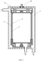
- This filter comprises a body 1 with a filter element 2 arranged inside.
- the filter element 2 is equipped with at least one outer scrubbing means 3 and at least one inner scrubbing means 4.
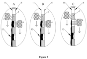
- the scrubbing means 3 and 4 can be made as brushes ( Figure 1 and 2 ), sponges, blades, or scrapers (not shown in the figures). Bristles of the brushes can be of different length - longer than the thickness of the filter element side walls ( Figure 2 , C), shorter ( Figure 2 , A) or about the same length ( Figure 2 , B) as the thickness of the filter element sidewalls.
- the inner scrubbing means 4 can be equipped with at least one flushing means ( Figure 3 ) for backwashing said filter element 2.
- This flushing means can be made as a tube 14 with a channel inside and two side tubes 16 and 17 with channels inside and apertures forming nozzles 15 or spigots (not shown).
- Said flushing means can be made as a separate construction (not shown) or be integrated with the mechanical inner scrubbing means 4 ( Figure 3 ).
- the flushing means can be made as a separate part of the filter (not shown), for example a nozzle or an injector, etc.
- the body 1 of the filter is made with an inlet 7 of raw liquid, an outlet 8 of purified liquid and an outlet 9 for drainage.
- the body 1 can be made of, for example, but not limited to, metal, for example, stainless steel or brasses, polymeric materials, for example polyolefins or any co-polymers thereof.
- the filter element 2 may be made as a mesh from metal or polymeric material.
- the filter element 2 may be cylindrical in shape, wherein the sidewall of the cylinder are made of a mesh.
- the mesh may be made corrugated to increase the surface. Any of the inner and the outer scrubbing means 4, 3 may be formed with a corrugated surface or can have an ability to wriggle.
- the filter element 2 can be made as mesh disks (not shown).
- the inner and the outer scrubbing means 4, 3 move due to, for example, but not limited to, electric driver 10 and a magnet 13 ( Figure 1 ) or a planetary drive.
- the filter element 2 and the inner and the outer scrubbing means 4, 3 move towards each other due to rotation (in the same or opposite direction) and/or translational motion of either the filter element 2 or the inner and outer scrubbing means 4, 3.
- the said embodiment of the filter works as follows.
- Raw liquid flows into the body 1 through inlet 7 and then flows through the filter element 2.
- Liquid purified from mechanical contaminants flows out from the purified liquid outlet 8 of the filter element 2 and through the purified liquid outlet of the body 1 ( Figure 1 ).
- a controller or a control panel of a water purification system in which the filter element 2 may be installed, sends a signal to perform backwashing of the filter element 2.
- the inner and outer scrubbing means 4, 3 may move around the filter element 2 which is fixed. Besides this, any of the scrubbing means 4, 3 may spin. Additionally, the filter element 2 may spin too.
- scrubbing is done, when the filter element 2 and the scrubbing means move translationally against each other - the filter element 2, for example, can move up and the scrubbing means move down, or vice versa.
- contaminants form dense plugs 12 on inner and outer surfaces 6, 11 of the filter element 2 and accumulate inside the mesh elements.
- the scrubbing means are accomplished to remove inner contaminants 13 and the dense plugs 12 from the inner and the outer surface 6, 11 of the filter element 2.
- the inner and the outer scrubbing means 4, 3 start to move along the filter element surface, removing mechanical contaminants.
- the start can be triggered by a signal of the control panel/controller received by said scrubbing means.
- Said signal can be provided by a timer of the controller (i.e. to start the move, the timer transmits a signal from time to time).
- the operator or user may press a button on the control panel of the water purification system which represent a signal for the controller to transmit a trigger for the start of the move.
- said scrubbing means may be move-not-stop means. In such a case e.g. installing the cartridge on the water purification system forms itself the trigger.
- the inner scrubbing means 4 penetrates inside the mesh elements, pushing contaminants out ( Figure 2 ).
- the outer scrubbing means 3 scrubs all the dirt (inner and outer) from the surface of the filter element 2. In case of high concentration of contaminants, any of the scrubbing means 3, 4 may operate during the whole filtration process.
- the bristles of the brush scrub the contaminants from the surface of the filter element 2 and penetrate at least partially into the inner space, or the openings of the mesh elements and, thus, totally remove all the contaminants ( Figure 2 ).
- the outer scrubbing means 3 is made in the form of a sponge (not shown), it is pressed against the filter elements surface and removes contaminants partly from the inner space of the mesh elements too.
- the filter is also equipped with at least one flushing means ( Figure 3 ), it further helps to remove contaminants. All drainage liquid flows out from the drainage outlet 9. The liquid flows along the channel of the tube 14 and then separates into two flows in the channels inside the two side tubes 16 and 17 ( Figure 3 ) and, through the nozzles 15 or spigots, spreads between brushes and washes away the dirt.
Landscapes
- Chemical & Material Sciences (AREA)
- Chemical Kinetics & Catalysis (AREA)
- Filtering Materials (AREA)
- Filtration Of Liquid (AREA)
Priority Applications (4)
| Application Number | Priority Date | Filing Date | Title |
|---|---|---|---|
| EP23166254.5A EP4438152B1 (de) | 2023-03-31 | 2023-03-31 | Filter |
| CN202480024023.8A CN121548452A (zh) | 2023-03-31 | 2024-04-02 | 过滤器 |
| PCT/IB2024/053201 WO2024201443A1 (en) | 2023-03-31 | 2024-04-02 | Filter |
| EP24722718.4A EP4704997A1 (de) | 2023-03-31 | 2024-04-02 | Filter |
Applications Claiming Priority (1)
| Application Number | Priority Date | Filing Date | Title |
|---|---|---|---|
| EP23166254.5A EP4438152B1 (de) | 2023-03-31 | 2023-03-31 | Filter |
Publications (3)
| Publication Number | Publication Date |
|---|---|
| EP4438152A1 true EP4438152A1 (de) | 2024-10-02 |
| EP4438152B1 EP4438152B1 (de) | 2025-11-19 |
| EP4438152C0 EP4438152C0 (de) | 2025-11-19 |
Family
ID=85800350
Family Applications (2)
| Application Number | Title | Priority Date | Filing Date |
|---|---|---|---|
| EP23166254.5A Active EP4438152B1 (de) | 2023-03-31 | 2023-03-31 | Filter |
| EP24722718.4A Pending EP4704997A1 (de) | 2023-03-31 | 2024-04-02 | Filter |
Family Applications After (1)
| Application Number | Title | Priority Date | Filing Date |
|---|---|---|---|
| EP24722718.4A Pending EP4704997A1 (de) | 2023-03-31 | 2024-04-02 | Filter |
Country Status (3)
| Country | Link |
|---|---|
| EP (2) | EP4438152B1 (de) |
| CN (1) | CN121548452A (de) |
| WO (1) | WO2024201443A1 (de) |
Citations (7)
| Publication number | Priority date | Publication date | Assignee | Title |
|---|---|---|---|---|
| US2354150A (en) | 1941-09-13 | 1944-07-18 | Ralph L Skinner | Cleanable filter |
| RU2424845C2 (ru) | 2006-10-20 | 2011-07-27 | Ханиуэлл Текнолоджиз Сарл Екк | Устройство для фильтрации жидкости, в частности, в установках домашнего обеспечения |
| KR20150056391A (ko) * | 2013-11-15 | 2015-05-26 | 주식회사 이노기술 | 배수기 |
| JP2015139743A (ja) | 2014-01-28 | 2015-08-03 | 株式会社御池鐵工所 | 回転篩機 |
| US20150265952A1 (en) * | 2014-03-18 | 2015-09-24 | Intake Screens, Inc. | Self-Cleaning Intake Screen |
| US20170368483A1 (en) * | 2016-06-28 | 2017-12-28 | Farmland Irrigation Research Institute, CAAS | multistage complex water screen filter with automatic alarm in micro-irrigation and its composition method |
| CN215842195U (zh) * | 2021-07-22 | 2022-02-18 | 日照博航新材料科技有限公司 | 一种改性有机硅树脂压缩制氮机 |
-
2023
- 2023-03-31 EP EP23166254.5A patent/EP4438152B1/de active Active
-
2024
- 2024-04-02 WO PCT/IB2024/053201 patent/WO2024201443A1/en not_active Ceased
- 2024-04-02 CN CN202480024023.8A patent/CN121548452A/zh active Pending
- 2024-04-02 EP EP24722718.4A patent/EP4704997A1/de active Pending
Patent Citations (7)
| Publication number | Priority date | Publication date | Assignee | Title |
|---|---|---|---|---|
| US2354150A (en) | 1941-09-13 | 1944-07-18 | Ralph L Skinner | Cleanable filter |
| RU2424845C2 (ru) | 2006-10-20 | 2011-07-27 | Ханиуэлл Текнолоджиз Сарл Екк | Устройство для фильтрации жидкости, в частности, в установках домашнего обеспечения |
| KR20150056391A (ko) * | 2013-11-15 | 2015-05-26 | 주식회사 이노기술 | 배수기 |
| JP2015139743A (ja) | 2014-01-28 | 2015-08-03 | 株式会社御池鐵工所 | 回転篩機 |
| US20150265952A1 (en) * | 2014-03-18 | 2015-09-24 | Intake Screens, Inc. | Self-Cleaning Intake Screen |
| US20170368483A1 (en) * | 2016-06-28 | 2017-12-28 | Farmland Irrigation Research Institute, CAAS | multistage complex water screen filter with automatic alarm in micro-irrigation and its composition method |
| CN215842195U (zh) * | 2021-07-22 | 2022-02-18 | 日照博航新材料科技有限公司 | 一种改性有机硅树脂压缩制氮机 |
Also Published As
| Publication number | Publication date |
|---|---|
| CN121548452A (zh) | 2026-02-17 |
| EP4704997A1 (de) | 2026-03-11 |
| EP4438152B1 (de) | 2025-11-19 |
| EP4438152C0 (de) | 2025-11-19 |
| WO2024201443A1 (en) | 2024-10-03 |
Similar Documents
| Publication | Publication Date | Title |
|---|---|---|
| JP6158581B2 (ja) | 濾過装置 | |
| KR102156816B1 (ko) | 여과 장치 | |
| KR101994188B1 (ko) | 여재를 이용한 오염수 정화장치 | |
| KR19990014757A (ko) | 유체 필터 시스템을 백워싱하기 위한 장치 및 방법 | |
| KR101468655B1 (ko) | 수처리용 여과장치 | |
| JP2009517204A (ja) | 洗浄装置 | |
| JP2021529931A (ja) | 空気浄化用の浄化装置およびそれを備える空気浄化器 | |
| FI4313354T3 (fi) | Sylinterimäinen suodatin vastahuuhtelusuuttimella | |
| EP4438152A1 (de) | Filter | |
| JP6608631B2 (ja) | 濾過装置及び濾過装置のフィルター洗浄方法 | |
| KR20150118323A (ko) | 수막필터 및 이를 이용한 공기정화기 | |
| KR100257861B1 (ko) | 자동여과장치 | |
| KR101946303B1 (ko) | 공기 청정기용 필터 장치 | |
| KR100380225B1 (ko) | 싸이클론식 연속여과기의 자동 역세 장치 | |
| KR100626306B1 (ko) | 중공사막 모듈을 이용한 수처리 장치 및 그 중공사막 모듈의 제조방법 | |
| KR100630372B1 (ko) | 여과장치 | |
| KR101226048B1 (ko) | 여과포가 부착된 규조토 드럼을 이용한 여과장치 | |
| KR102015536B1 (ko) | 다중 에어필터 자동세척 장치 | |
| KR20250111677A (ko) | 여과망 접촉 차단 가이드 벽체와 보조배출관이 구비된 부상슬러지와 침전슬러지의 연속 분리 배출 장치 | |
| JP2003225517A (ja) | 固液分離装置の洗浄方法 | |
| KR101837616B1 (ko) | 필터 조립체 및 수처리 장치 | |
| KR100759985B1 (ko) | 사여과장치 및 그 세정방법 | |
| KR101951521B1 (ko) | 여과와 세척의 동시 수행이 가능한 여과기 | |
| KR100598135B1 (ko) | 수중 자동세척식 호소수 여과장치 및 그 세척방법 | |
| KR102733028B1 (ko) | 수직 이동 및 수평 회전하는 세척 노즐이 구비된 부상슬러지와 침전슬러지의 연속 분리 배출 장치 |
Legal Events
| Date | Code | Title | Description |
|---|---|---|---|
| PUAI | Public reference made under article 153(3) epc to a published international application that has entered the european phase |
Free format text: ORIGINAL CODE: 0009012 |
|
| STAA | Information on the status of an ep patent application or granted ep patent |
Free format text: STATUS: THE APPLICATION HAS BEEN PUBLISHED |
|
| AK | Designated contracting states |
Kind code of ref document: A1 Designated state(s): AL AT BE BG CH CY CZ DE DK EE ES FI FR GB GR HR HU IE IS IT LI LT LU LV MC ME MK MT NL NO PL PT RO RS SE SI SK SM TR |
|
| STAA | Information on the status of an ep patent application or granted ep patent |
Free format text: STATUS: REQUEST FOR EXAMINATION WAS MADE |
|
| 17P | Request for examination filed |
Effective date: 20250402 |
|
| GRAP | Despatch of communication of intention to grant a patent |
Free format text: ORIGINAL CODE: EPIDOSNIGR1 |
|
| STAA | Information on the status of an ep patent application or granted ep patent |
Free format text: STATUS: GRANT OF PATENT IS INTENDED |
|
| INTG | Intention to grant announced |
Effective date: 20250612 |
|
| GRAS | Grant fee paid |
Free format text: ORIGINAL CODE: EPIDOSNIGR3 |
|
| GRAA | (expected) grant |
Free format text: ORIGINAL CODE: 0009210 |
|
| STAA | Information on the status of an ep patent application or granted ep patent |
Free format text: STATUS: THE PATENT HAS BEEN GRANTED |
|
| AK | Designated contracting states |
Kind code of ref document: B1 Designated state(s): AL AT BE BG CH CY CZ DE DK EE ES FI FR GB GR HR HU IE IS IT LI LT LU LV MC ME MK MT NL NO PL PT RO RS SE SI SK SM TR |
|
| REG | Reference to a national code |
Ref country code: CH Ref legal event code: F10 Free format text: ST27 STATUS EVENT CODE: U-0-0-F10-F00 (AS PROVIDED BY THE NATIONAL OFFICE) Effective date: 20251119 Ref country code: GB Ref legal event code: FG4D |
|
| REG | Reference to a national code |
Ref country code: DE Ref legal event code: R096 Ref document number: 602023008653 Country of ref document: DE |
|
| REG | Reference to a national code |
Ref country code: IE Ref legal event code: FG4D |
|
| U01 | Request for unitary effect filed |
Effective date: 20251219 |
|
| REG | Reference to a national code |
Ref country code: CH Ref legal event code: R17 Free format text: ST27 STATUS EVENT CODE: U-0-0-R10-R17 (AS PROVIDED BY THE NATIONAL OFFICE) Effective date: 20260304 |
|
| U07 | Unitary effect registered |
Designated state(s): AT BE BG DE DK EE FI FR IT LT LU LV MT NL PT RO SE SI Effective date: 20260209 |
|
| U20 | Renewal fee for the european patent with unitary effect paid |
Year of fee payment: 4 Effective date: 20260205 |
|
| REG | Reference to a national code |
Ref country code: CH Ref legal event code: U11 Free format text: ST27 STATUS EVENT CODE: U-0-0-U10-U11 (AS PROVIDED BY THE NATIONAL OFFICE) Effective date: 20260401 |
|
| PG25 | Lapsed in a contracting state [announced via postgrant information from national office to epo] |
Ref country code: ES Free format text: LAPSE BECAUSE OF FAILURE TO SUBMIT A TRANSLATION OF THE DESCRIPTION OR TO PAY THE FEE WITHIN THE PRESCRIBED TIME-LIMIT Effective date: 20251119 |
|
| PG25 | Lapsed in a contracting state [announced via postgrant information from national office to epo] |
Ref country code: NO Free format text: LAPSE BECAUSE OF FAILURE TO SUBMIT A TRANSLATION OF THE DESCRIPTION OR TO PAY THE FEE WITHIN THE PRESCRIBED TIME-LIMIT Effective date: 20260219 |
|
| PG25 | Lapsed in a contracting state [announced via postgrant information from national office to epo] |
Ref country code: HR Free format text: LAPSE BECAUSE OF FAILURE TO SUBMIT A TRANSLATION OF THE DESCRIPTION OR TO PAY THE FEE WITHIN THE PRESCRIBED TIME-LIMIT Effective date: 20251119 |
|
| PGFP | Annual fee paid to national office [announced via postgrant information from national office to epo] |
Ref country code: RS Payment date: 20260320 Year of fee payment: 4 |
|
| PG25 | Lapsed in a contracting state [announced via postgrant information from national office to epo] |
Ref country code: IS Free format text: LAPSE BECAUSE OF FAILURE TO SUBMIT A TRANSLATION OF THE DESCRIPTION OR TO PAY THE FEE WITHIN THE PRESCRIBED TIME-LIMIT Effective date: 20260319 |
|
| PGFP | Annual fee paid to national office [announced via postgrant information from national office to epo] |
Ref country code: CZ Payment date: 20260324 Year of fee payment: 4 |