EP4438191A1 - Tête de brosse à vapeur et appareil de nettoyage - Google Patents
Tête de brosse à vapeur et appareil de nettoyage Download PDFInfo
- Publication number
- EP4438191A1 EP4438191A1 EP22941370.3A EP22941370A EP4438191A1 EP 4438191 A1 EP4438191 A1 EP 4438191A1 EP 22941370 A EP22941370 A EP 22941370A EP 4438191 A1 EP4438191 A1 EP 4438191A1
- Authority
- EP
- European Patent Office
- Prior art keywords
- channel
- steam
- cleaning
- brush head
- brush
- Prior art date
- Legal status (The legal status is an assumption and is not a legal conclusion. Google has not performed a legal analysis and makes no representation as to the accuracy of the status listed.)
- Pending
Links
Images



Classifications
-
- B—PERFORMING OPERATIONS; TRANSPORTING
- B08—CLEANING
- B08B—CLEANING IN GENERAL; PREVENTION OF FOULING IN GENERAL
- B08B1/00—Cleaning by methods involving the use of tools
- B08B1/10—Cleaning by methods involving the use of tools characterised by the type of cleaning tool
- B08B1/12—Brushes
-
- A—HUMAN NECESSITIES
- A46—BRUSHWARE
- A46B—BRUSHES
- A46B11/00—Brushes with reservoir or other means for applying substances, e.g. paints, pastes, water
- A46B11/06—Brushes with reservoir or other means for applying substances, e.g. paints, pastes, water connected to supply pipe or to other external supply means
-
- A—HUMAN NECESSITIES
- A46—BRUSHWARE
- A46B—BRUSHES
- A46B7/00—Bristle carriers arranged in the brush body
- A46B7/04—Bristle carriers arranged in the brush body interchangeably removable bristle carriers
-
- A—HUMAN NECESSITIES
- A47—FURNITURE; DOMESTIC ARTICLES OR APPLIANCES; COFFEE MILLS; SPICE MILLS; SUCTION CLEANERS IN GENERAL
- A47L—DOMESTIC WASHING OR CLEANING; SUCTION CLEANERS IN GENERAL
- A47L11/00—Machines for cleaning floors, carpets, furniture, walls, or wall coverings
- A47L11/29—Floor-scrubbing machines characterised by means for taking-up dirty liquid
- A47L11/30—Floor-scrubbing machines characterised by means for taking-up dirty liquid by suction
-
- A—HUMAN NECESSITIES
- A47—FURNITURE; DOMESTIC ARTICLES OR APPLIANCES; COFFEE MILLS; SPICE MILLS; SUCTION CLEANERS IN GENERAL
- A47L—DOMESTIC WASHING OR CLEANING; SUCTION CLEANERS IN GENERAL
- A47L11/00—Machines for cleaning floors, carpets, furniture, walls, or wall coverings
- A47L11/34—Machines for treating carpets in position by liquid, foam, or vapour, e.g. by steam
-
- A—HUMAN NECESSITIES
- A47—FURNITURE; DOMESTIC ARTICLES OR APPLIANCES; COFFEE MILLS; SPICE MILLS; SUCTION CLEANERS IN GENERAL
- A47L—DOMESTIC WASHING OR CLEANING; SUCTION CLEANERS IN GENERAL
- A47L11/00—Machines for cleaning floors, carpets, furniture, walls, or wall coverings
- A47L11/40—Parts or details of machines not provided for in groups A47L11/02 - A47L11/38, or not restricted to one of these groups, e.g. handles, arrangements of switches, skirts, buffers, levers
- A47L11/4036—Parts or details of the surface treating tools
-
- A—HUMAN NECESSITIES
- A47—FURNITURE; DOMESTIC ARTICLES OR APPLIANCES; COFFEE MILLS; SPICE MILLS; SUCTION CLEANERS IN GENERAL
- A47L—DOMESTIC WASHING OR CLEANING; SUCTION CLEANERS IN GENERAL
- A47L11/00—Machines for cleaning floors, carpets, furniture, walls, or wall coverings
- A47L11/40—Parts or details of machines not provided for in groups A47L11/02 - A47L11/38, or not restricted to one of these groups, e.g. handles, arrangements of switches, skirts, buffers, levers
- A47L11/4036—Parts or details of the surface treating tools
- A47L11/4044—Vacuuming or pick-up tools; Squeegees
-
- A—HUMAN NECESSITIES
- A47—FURNITURE; DOMESTIC ARTICLES OR APPLIANCES; COFFEE MILLS; SPICE MILLS; SUCTION CLEANERS IN GENERAL
- A47L—DOMESTIC WASHING OR CLEANING; SUCTION CLEANERS IN GENERAL
- A47L11/00—Machines for cleaning floors, carpets, furniture, walls, or wall coverings
- A47L11/40—Parts or details of machines not provided for in groups A47L11/02 - A47L11/38, or not restricted to one of these groups, e.g. handles, arrangements of switches, skirts, buffers, levers
- A47L11/408—Means for supplying cleaning or surface treating agents
- A47L11/4088—Supply pumps; Spraying devices; Supply conduits
-
- A—HUMAN NECESSITIES
- A47—FURNITURE; DOMESTIC ARTICLES OR APPLIANCES; COFFEE MILLS; SPICE MILLS; SUCTION CLEANERS IN GENERAL
- A47L—DOMESTIC WASHING OR CLEANING; SUCTION CLEANERS IN GENERAL
- A47L25/00—Domestic cleaning devices not provided for in other groups of this subclass
-
- B—PERFORMING OPERATIONS; TRANSPORTING
- B08—CLEANING
- B08B—CLEANING IN GENERAL; PREVENTION OF FOULING IN GENERAL
- B08B1/00—Cleaning by methods involving the use of tools
- B08B1/40—Cleaning tools with integrated means for dispensing fluids, e.g. water, steam or detergents
-
- B—PERFORMING OPERATIONS; TRANSPORTING
- B08—CLEANING
- B08B—CLEANING IN GENERAL; PREVENTION OF FOULING IN GENERAL
- B08B1/00—Cleaning by methods involving the use of tools
- B08B1/50—Cleaning by methods involving the use of tools involving cleaning of the cleaning members
- B08B1/52—Cleaning by methods involving the use of tools involving cleaning of the cleaning members using fluids
-
- B—PERFORMING OPERATIONS; TRANSPORTING
- B08—CLEANING
- B08B—CLEANING IN GENERAL; PREVENTION OF FOULING IN GENERAL
- B08B3/00—Cleaning by methods involving the use or presence of liquid or steam
- B08B3/02—Cleaning by the force of jets or sprays
-
- A—HUMAN NECESSITIES
- A46—BRUSHWARE
- A46B—BRUSHES
- A46B2200/00—Brushes characterized by their functions, uses or applications
- A46B2200/30—Brushes for cleaning or polishing
-
- B—PERFORMING OPERATIONS; TRANSPORTING
- B08—CLEANING
- B08B—CLEANING IN GENERAL; PREVENTION OF FOULING IN GENERAL
- B08B2230/00—Other cleaning aspects applicable to all B08B range
- B08B2230/01—Cleaning with steam
Definitions
- This invention generally relates to the technical field of cleaning, and more particularly, to a steam brush head and a cleaning apparatus.
- Conventional cleaning apparatuses used to clean the surface of an object normally only have a water spray function. Namely, the cleaning apparatus only sprays water onto the surface to be cleaned for washing and cleaning.
- additional steam pipelines need to be added, and the process is complex. Due to the structural limitation, conventional fabric cleaning machines often directly spray steam onto the surface to be cleaned, resulting in quick dissipation of steam. Moreover, the speed of spraying steam is slow, failing to meet the cleaning needs. Therefore, it's difficult for conventional cleaning apparatuses to achieve ideal steam cleaning effect.
- the purpose of the present invention is to provide a steam brush head that has a simple and compact structure and high cleaning performance, as well as a cleaning apparatus having the said steam brush head.
- a steam brush head comprises: a brush seat assembly, which is provided with a chamber communicated with the outside, and a first channel and a second channel which are communicated with the outside, a plurality of notches being formed on an outer edge of an opening end of the brush seat assembly; and a brush head assembly, provided in the chamber of the brush seat assembly and communicated with the second channel; the first channel is used for forming a dust removal channel; the second channel is used for forming a cleaning channel for conveying steam or cleaning water; the opening end of the brush seat assembly is capable of being pressed to cover a surface to be cleaned, such that the chamber and the surface to be cleaned cooperate to define a cleaning chamber; the notches and the surface to be cleaned cooperate to define air vents communicated with the cleaning chamber; the second channel and the first channel are both communicated with the cleaning chamber; steam or cleaning water sprayed out from the second channel enters the cleaning chamber to clean the surface to be cleaned; and waste steam or wastewater after cleaning is completed flows
- the brush seat assembly comprises a brush seat, wherein a chamber is provided inside the brush seat, and the plurality of notches are provided at the opening end of the brush seat; and a dust cover, wherein the dust cover covers the brush seat and is provided with a channel slot for cooperating with the outer side wall of the brush seat to define the first channel with two opening ends.
- a backflow channel is arranged for communicating one side of the brush seat and one side of the dust cover that face the surface to be cleaned. Two ends of the backflow channel are respectively in communication with the cleaning chamber and the dust removal channel. The waste steam or waste water in the cleaning chamber flows into the dust removal channel through the backflow channel and is discharged therefrom.
- the opening end of the brush seat comprises a plurality of side edges
- the backflow channel on the brush seat goes through a first side edge of the opening end to extend into the dust cover
- the plurality of notches are respectively arranged at side edges other than the first side edge
- a nozzle assembly is arranged in the second channel in the brush seat for spraying steam or cleaning water, and steam or cleaning water sprayed by the nozzle assembly is sprayed from the brush head assembly to a surface to be cleaned.
- the brush head assembly comprises a brush head having a plurality of clusters of bristles, the brush head is installed in the chamber and adjacent to the opening end, the brush head is provided with a through hole, and the second channel, the nozzle assembly and the cleaning chamber are both in communication with the through hole.
- the nozzle assembly comprises a connecting nozzle connected to a port of the second channel, a steam connector cover connected to the brush head and the connecting nozzle, and a steel sheet fixed at a position where the through hole of the brush head is located.
- the steel sheet is provided with a plurality of spray holes, and the plurality of spray holes are arranged in a linear shape.
- the steam brush head comprises a handle rod that has a hollow structure and is connected to the brush seat assembly, wherein the first channel is communicated with the handle rod to form the dust removal channel; and a water pipe assembly that extends into the handle rod and is communicated with the second channel to form the cleaning channel for delivering steam or cleaning water.
- the water pipe assembly comprises a water pipe and a water pipe joint assembly, and the water pipe extends into the handle rod through the water pipe joint assembly to communicate with the brush seat and the second channel to form the cleaning channel.
- the present invention also provides a cleaning apparatus comprising the steam brush head in any one of above embodiments.
- the present invention has the following advantages: by providing the first channel and the second channel, a dust removal channel and a cleaning channel are respectively formed by the two channels; the cleaning channel is capable of delivering steam or cleaning water, achieving two-in-one function; in this way, it is unnecessary to arrange two different pipelines, which greatly saves costs and installation space while significantly improving structural compactness; furthermore, the chamber of the brush seat assembly and the surface to be cleaned cooperate to define the cleaning chamber, the first channel and the second channel are in communication with the cleaning chamber, the plurality of notches are formed on the opening end of the brush seat assembly, and the notches form air vents communicated with the cleaning chamber; at this point, the pressure difference between the interior and exterior of the cleaning chamber is zero, which effectively ensures that the steam smoothly enters the dust removal channel from the cleaning channel; meanwhile, the quick dissipation of steam is avoided, enabling the steam to stay in the cleaning chamber for a prolonged period of time for cleaning the surface to be cleaned, thereby further improving the cleaning strength.
- the present invention provides a steam brush head.
- the steam brush head comprises: a brush seat assembly, which is provided with a chamber communicated with the outside, and a first channel and a second channel which are communicated with the outside, a plurality of notches 14 being formed on an outer edge of an opening end of the brush seat assembly; and a brush head assembly, provided in the chamber of the brush seat assembly and communicated with the second channel.
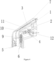
- the first channel is used for forming a dust removal channel 3; the second channel is used for forming a cleaning channel 4 for conveying steam or cleaning water; the opening end of the brush seat assembly can be pressed to cover a surface to be cleaned, such that the chamber and the surface to be cleaned cooperate to define a cleaning chamber 15; the notches 14 and the surface to be cleaned cooperate to define air vents communicated with the cleaning chamber; the second channel and the first channel are both communicated with the cleaning chamber 15; steam or cleaning water sprayed out from the second channel enters the cleaning chamber 15 to clean the surface to be cleaned; and waste steam or wastewater after cleaning is completed flows into the first channel through the cleaning chamber 15.
- the steam brush head may be applied to a cleaning apparatus having a steam function.
- the steam brush head has a simple structure comprising a brush seat assembly and a brush head assembly.
- the cleaning chamber 15 is defined by the brush seat assembly and the surface to be cleaned, and the plurality of notches 14 formed in the opening end of the brush seat assembly cooperate with the surface to be cleaned to define air vents in communication with the cleaning chamber 15.
- the sprayed steam or cleaning water are restricted in the cleaning chamber 15 for cleaning, and the duration of contact (namely, the cleaning time) between the steam and the surface to be cleaned is prolonged.
- the cleaning strength is improved, and the waste steam or waste water are prevented from overflowing.
- the waste steam or waste water may flow into the first channel (namely, the dust removal channel 3) from the cleaning chamber 15 and is discharged from the dust removal channel 3.
- a dust removal channel and a cleaning channel are respectively formed by the two channels.
- the cleaning channel is capable of delivering steam or cleaning water, achieving two-in-one function. In this way, it is unnecessary to arrange two different pipelines, which greatly saves costs and installation space while significantly improving structural compactness.
- the chamber of the brush seat assembly and the surface to be cleaned cooperate to define the cleaning chamber, the first channel and the second channel are in communication with the cleaning chamber, the plurality of notches are formed on the opening end of the brush seat assembly, and the notches form air vents communicated with the cleaning chamber. At this point, the pressure difference between the interior and exterior of the cleaning chamber is zero, which effectively ensures that the steam smoothly enters the dust removal channel from the cleaning channel.
- the quick dissipation of steam is avoided, enabling the steam to stay in the cleaning chamber for a prolonged period of time for cleaning the surface to be cleaned, thereby further improving the cleaning strength.
- the cleaning water or the steam flows into the dust removal channel 3 from the cleaning chamber 15 for being discharged, which effectively prevents the surface to be cleaned from a secondary pollution, avoiding the manual cleaning and significantly improving the use convenience.
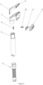
- the brush seat assembly comprises a brush seat 1, wherein a chamber is provided inside the brush seat 1, and the plurality of notches are provided at the opening end of the brush seat 1; and a dust cover 7, wherein the dust cover covers the brush seat 1 and is provided with a channel slot 8 for cooperating with the outer side wall of the brush seat to define the first channel with two opening ends.
- the brush seat 1 has a head portion and a tail portion, and a connection angle is formed between the head portion and the tail portion.
- the head portion and the tail portion communicating with each other through a chamber.
- the dust cover 7 resembles the brush seat 1 and is capable of serving as a cover for covering the whole outer side wall of the brush seat 1, and a side of the dust cover 7 facing the brush seat 1 is provided with the channel slot 8. After the dust cover 7 covers the outside of the brush seat 1, the brush seat 1 cooperates with the channel slot 8 to form the first channel with two opening ends.
- a side of the brush head 2 facing the surface to be cleaned is provided with a plurality of clusters of bristles, and the plurality of clusters of bristles are arranged in the cleaning chamber 15.
- a nozzle assembly is arranged in the cleaning channel 4, namely, the nozzle assembly being in communication with the second channel. The nozzle assembly allows steam or cleaning water to be sprayed onto the brush head assembly, thereby facilitating the cleaning of the surface to be cleaned.
- the brush head assembly is arranged in the chamber of the brush seat 1.
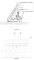
- the opening end of the brush seat is arranged on the surface to be cleaned, and the outer edge of the opening end of the brush seat abuts against the surface to be cleaned, thereby forming the cleaning chamber 15 between the chamber of the brush seat 1 and the surface to be cleaned.
- the outer edge of the opening end of the brush seat 1 is further provided with notches 14 in communication with the cleaning chamber 15.
- each of the notches 14 may be arranged on each edge, wherein the notch 14 may be a gap formed on the edge for cooperating with the surface to be cleaned to form a closed hole body, namely, an air vent.
- the notch may also be an air hole directly formed at the edge, which is not specifically determined.
- a backflow channel 13 is arranged for communicating one side of the brush seat 1 and one side of the dust cover 7 that face the surface to be cleaned.
- Two ends of the backflow channel 13 are respectively in communication with the cleaning chamber 15 and the dust removal channel 3.
- the backflow channel 13 may penetrate through the brush seat 1 and the dust cover 7 and is respectively in communication with the cleaning chamber 15 and the dust removal channel 3.
- the waste steam or waste water in the cleaning chamber 15 flows into the dust removal channel through the backflow channel and is discharged therefrom.
- the brush head assembly comprises a brush head 2, and the brush head 2 is installed at the opening end of the chamber of the brush seat 1.
- the brush head 2 has a through hole, and the second channel, the cleaning chamber 15 and the nozzle assembly are in communication with the through hole.
- the opening end of the brush seat 1 is configured to be rectangular.
- the opening end of the brush seat 1 comprises a first side edge connected to the dust cover 7 and provided with the backflow channel 13, and a second side edge connected to the first side edge to form a rectangular frame.
- the plurality of notches 14 are respectively arranged on the second side edge.
- the steam brush head comprises a handle rod 5 that has a hollow structure and is connected to the brush seat assembly, wherein the first channel is communicated with the handle rod 5 to form the dust removal channel 3; and a water pipe assembly 6 that extends into the handle rod 5 and is communicated with the second channel to form the cleaning channel 4 for delivering steam or cleaning water, wherein the handle rod 5 and the brush seat 1 are detachably connected.
- the water pipe assembly 6 comprises a water pipe and a water pipe joint assembly, wherein the water pipe joint assembly further comprises a water pipe joint 9 and a connecting pipe connected to the water pipe and the water pipe joint.
- the water pipe extends into the handle rod 5 through the water pipe joint assembly and is connected to the brush seat 1 while being communicated with the second channel, thereby forming the cleaning channel 4.
- at least the water pipe assembly 6 and the second channel cooperate to form the cleaning channel 4.
- the nozzle assembly comprises a connecting nozzle 10 connected to a port of the second channel, a steam connector cover 11 connected to the brush head 2 and the connecting nozzle 10, and a steel sheet 12 fixed at a through hole of the brush head 2.
- the steel sheet 12 is provided with a plurality of spray holes 16, and the plurality of spray holes are arranged in a linear shape.
- the spray holes may also be arranged in other manners.
- the dust cover 7 and the channel slot 8 in the brush seat 1 cooperate to define the dust removal channel, which serves as a dust suction pipeline.
- the dust cover 7 and the brush seat 1 are installed on the handle rod 5 and are fixed by using buckles.
- the water pipe 6 is connected to the water pipe joint 9.
- the cleaning water or steam flows through the water pipe 6, the second channel, the water pipe joint 9 and the connecting nozzle 10, and finally enters the brush head 2 through the through hole in the brush head 2.
- the steel sheet 12 is arranged at the position where the through hole is located, so that the cleaning water or steam is sprayed out from the spray hole in the steel sheet 12 to the outside.
- the diameter of the spray hole ranges from 0.2-0.4.
- the steel sheet 12 On the premise of ensuring the flow rate of steam or cleaning water, a small diameter ensures the sufficient pressure of steam or water flow such that a proper sprayed strength is achieved.
- the steel sheet 12, the brush seat 1 and the handle rod 5 have high temperature resistance, ensuring the functional life of the nozzle and achieving high use safety.
- the steel sheet 12 is provided with a row of spray holes, which not only ensures the flow rate, but also ensures that the flow rate within the standard time is sufficient to meet the cleaning requirements.
- the dust removal channel when in use, is closely attached to the surface to be cleaned such that the dust removal effect is significantly improved.
- the closed chamber is filled with steam or water.
- the closed chamber is a recessed space formed by inserting the brush head 2 into the brush seat 1.
- the closed chamber is used for assisting in improving the steam effect or the water spray effect (especially the steam effect). If it is not a closed chamber, leakage of steam may occur, resulting in poor cleaning effect and damage to the user.
- the closed chamber ensures high use safety and ideal cleaning effect.
- Another preferred embodiment of the present invention provides a cleaning apparatus comprising the steam brush head in any one of above embodiments.
Landscapes
- Brushes (AREA)
Applications Claiming Priority (2)
| Application Number | Priority Date | Filing Date | Title |
|---|---|---|---|
| CN202221162955.3U CN217165422U (zh) | 2022-05-13 | 2022-05-13 | 一种蒸汽刷头及清洁装置 |
| PCT/CN2022/108460 WO2023216427A1 (fr) | 2022-05-13 | 2022-07-28 | Tête de brosse à vapeur et appareil de nettoyage |
Publications (2)
| Publication Number | Publication Date |
|---|---|
| EP4438191A1 true EP4438191A1 (fr) | 2024-10-02 |
| EP4438191A4 EP4438191A4 (fr) | 2025-06-04 |
Family
ID=82712202
Family Applications (1)
| Application Number | Title | Priority Date | Filing Date |
|---|---|---|---|
| EP22941370.3A Pending EP4438191A4 (fr) | 2022-05-13 | 2022-07-28 | Tête de brosse à vapeur et appareil de nettoyage |
Country Status (5)
| Country | Link |
|---|---|
| EP (1) | EP4438191A4 (fr) |
| JP (1) | JP3251008U (fr) |
| KR (1) | KR20240001327U (fr) |
| CN (1) | CN217165422U (fr) |
| WO (1) | WO2023216427A1 (fr) |
Cited By (1)
| Publication number | Priority date | Publication date | Assignee | Title |
|---|---|---|---|---|
| WO2025215120A1 (fr) * | 2024-04-09 | 2025-10-16 | Alfred Kärcher SE & Co. KG | Embout de buse, buse d'aspiration, tuyau d'appareil de nettoyage et appareil de nettoyage |
Families Citing this family (2)
| Publication number | Priority date | Publication date | Assignee | Title |
|---|---|---|---|---|
| CN217165422U (zh) * | 2022-05-13 | 2022-08-12 | 广东东菱电器有限公司 | 一种蒸汽刷头及清洁装置 |
| CN118140893B (zh) * | 2022-12-05 | 2025-10-17 | 莱克电气股份有限公司 | 除螨仪 |
Family Cites Families (18)
| Publication number | Priority date | Publication date | Assignee | Title |
|---|---|---|---|---|
| CH646044A5 (de) * | 1983-01-26 | 1984-11-15 | Gottfried Gremminger | Flaechen-reinigungsgeraet. |
| US5588176A (en) * | 1995-06-12 | 1996-12-31 | Thomas G. Sixsmith | Water recovery wash brush |
| DE19545517C2 (de) * | 1995-12-06 | 1998-12-03 | Iren Dornier | Dampfreinigungsvorrichtung |
| JP3082936U (ja) * | 2001-06-20 | 2002-01-11 | 連 寶 呉 | 蒸気ブラシヘッド固定構造 |
| CN2637007Y (zh) * | 2003-08-15 | 2004-09-01 | 陈焕强 | 一种蒸汽驱动的刷头 |
| US7578025B2 (en) | 2006-05-16 | 2009-08-25 | Royal Appliance Mfg. Co. | Battery powered cleaning attachment |
| AU2010246496B2 (en) * | 2009-12-03 | 2013-11-07 | Bissell Inc. | Steam mop with shuttling steam distributor |
| CN201842063U (zh) * | 2010-11-10 | 2011-05-25 | 宁波雪芸机械工贸有限公司 | 用于蒸汽洗车机的洗刷头 |
| GB2515747A (en) | 2013-07-01 | 2015-01-07 | Techtronic Floor Care Tech Ltd | Surface cleaning apparatus |
| US9282869B2 (en) * | 2014-02-28 | 2016-03-15 | Rug Doctor, LLC | Liquid extraction cleaning device and method |
| WO2017166012A1 (fr) * | 2016-03-28 | 2017-10-05 | 邢皓宇 | Brosse à vapeur |
| CN206666895U (zh) * | 2017-04-21 | 2017-11-24 | 宁波长利塑料电器有限公司 | 一种蒸汽刷 |
| CN207236747U (zh) * | 2017-04-25 | 2018-04-17 | 广州畅途汽车技术开发有限公司 | 一种蒸汽清洁刷 |
| CN208050460U (zh) * | 2018-01-15 | 2018-11-06 | 宁波安珂电器科技有限公司 | 一种蒸汽清洁装置 |
| KR102418364B1 (ko) | 2019-08-01 | 2022-07-06 | 산시 지아스다 로봇 테크놀러지 컴퍼니 리미티드 | 진공청소기 브러시 헤드 및 흡진 방법 |
| CN216040331U (zh) * | 2021-09-27 | 2022-03-15 | 上海飞科电器股份有限公司 | 蒸汽刷 |
| CN113974481B (zh) * | 2021-11-03 | 2022-11-01 | 广东电网有限责任公司 | 电控柜清扫装置 |
| CN217165422U (zh) * | 2022-05-13 | 2022-08-12 | 广东东菱电器有限公司 | 一种蒸汽刷头及清洁装置 |
-
2022
- 2022-05-13 CN CN202221162955.3U patent/CN217165422U/zh active Active
- 2022-07-28 KR KR2020247000035U patent/KR20240001327U/ko active Pending
- 2022-07-28 JP JP2024600107U patent/JP3251008U/ja active Active
- 2022-07-28 EP EP22941370.3A patent/EP4438191A4/fr active Pending
- 2022-07-28 WO PCT/CN2022/108460 patent/WO2023216427A1/fr not_active Ceased
Cited By (1)
| Publication number | Priority date | Publication date | Assignee | Title |
|---|---|---|---|---|
| WO2025215120A1 (fr) * | 2024-04-09 | 2025-10-16 | Alfred Kärcher SE & Co. KG | Embout de buse, buse d'aspiration, tuyau d'appareil de nettoyage et appareil de nettoyage |
Also Published As
| Publication number | Publication date |
|---|---|
| CN217165422U (zh) | 2022-08-12 |
| KR20240001327U (ko) | 2024-08-06 |
| EP4438191A4 (fr) | 2025-06-04 |
| JP3251008U (ja) | 2025-04-21 |
| WO2023216427A1 (fr) | 2023-11-16 |
Similar Documents
| Publication | Publication Date | Title |
|---|---|---|
| EP4438191A1 (fr) | Tête de brosse à vapeur et appareil de nettoyage | |
| CN107488980B (zh) | 清洗喷淋元件、前外桶、门密封圈及其清洗方法和洗衣机 | |
| CN218322007U (zh) | 一种喷嘴组件及衣物处理设备 | |
| CN215584016U (zh) | 一种滚刷给水结构及清洁设备 | |
| CN210846803U (zh) | 一种高压清洗喷头 | |
| CN217090620U (zh) | 一种喷嘴装置及清洁头 | |
| CN216876225U (zh) | 清洁组件和具有它的清洁机 | |
| CN210204632U (zh) | 一种喷头组件及手持式清洁装置 | |
| CN217365652U (zh) | 清洁头及清洁装置 | |
| CN219289363U (zh) | 地面清洁设备的地刷装置和地面清洁设备 | |
| CN214617199U (zh) | 一种风机和清洗机 | |
| CN216876223U (zh) | 地刷头和具有它的清洁装置 | |
| CN223640647U (zh) | 具有三通阀装置的清洗机 | |
| CN213855910U (zh) | 一种清洗装置射流底盘 | |
| EP4446022A1 (fr) | Agencement de rinçage de réservoir | |
| CN112323936B (zh) | 一种智能马桶的起泡装置及智能马桶 | |
| CN218635903U (zh) | 一种自清洁装置及清洁设备 | |
| CN208123563U (zh) | 软水阀和软水机 | |
| CN220371839U (zh) | 基站的污水箱及基站 | |
| CN211816719U (zh) | 一种鼓吹喷头及坐便器外部清洁系统 | |
| CN214784348U (zh) | 箱式无负压供水设备 | |
| CN223715541U (zh) | 防虹吸水路组件及具有蒸功能的烹饪设备 | |
| CN223268944U (zh) | 一种衣物处理设备 | |
| CN217429896U (zh) | 一种用于清洁机的分液器及地刷模块 | |
| JP2006181041A (ja) | 湿式電気掃除機用吸引ノズル |
Legal Events
| Date | Code | Title | Description |
|---|---|---|---|
| STAA | Information on the status of an ep patent application or granted ep patent |
Free format text: STATUS: THE INTERNATIONAL PUBLICATION HAS BEEN MADE |
|
| PUAI | Public reference made under article 153(3) epc to a published international application that has entered the european phase |
Free format text: ORIGINAL CODE: 0009012 |
|
| STAA | Information on the status of an ep patent application or granted ep patent |
Free format text: STATUS: REQUEST FOR EXAMINATION WAS MADE |
|
| 17P | Request for examination filed |
Effective date: 20240625 |
|
| AK | Designated contracting states |
Kind code of ref document: A1 Designated state(s): AL AT BE BG CH CY CZ DE DK EE ES FI FR GB GR HR HU IE IS IT LI LT LU LV MC MK MT NL NO PL PT RO RS SE SI SK SM TR |
|
| TPAC | Observations filed by third parties |
Free format text: ORIGINAL CODE: EPIDOSNTIPA |
|
| A4 | Supplementary search report drawn up and despatched |
Effective date: 20250508 |
|
| RIC1 | Information provided on ipc code assigned before grant |
Ipc: A47L 11/40 20060101ALI20250430BHEP Ipc: A47L 11/34 20060101ALI20250430BHEP Ipc: A47L 11/30 20060101ALI20250430BHEP Ipc: A46B 11/06 20060101ALI20250430BHEP Ipc: B08B 3/02 20060101ALI20250430BHEP Ipc: B08B 1/00 20240101AFI20250430BHEP |
|
| DAV | Request for validation of the european patent (deleted) | ||
| DAX | Request for extension of the european patent (deleted) | ||
| GRAP | Despatch of communication of intention to grant a patent |
Free format text: ORIGINAL CODE: EPIDOSNIGR1 |
|
| STAA | Information on the status of an ep patent application or granted ep patent |
Free format text: STATUS: GRANT OF PATENT IS INTENDED |