EP4438413A1 - Barre de support de charge avec joint d'étanchéité - Google Patents
Barre de support de charge avec joint d'étanchéité Download PDFInfo
- Publication number
- EP4438413A1 EP4438413A1 EP24164053.1A EP24164053A EP4438413A1 EP 4438413 A1 EP4438413 A1 EP 4438413A1 EP 24164053 A EP24164053 A EP 24164053A EP 4438413 A1 EP4438413 A1 EP 4438413A1
- Authority
- EP
- European Patent Office
- Prior art keywords
- channel
- seal
- load carrying
- carrying bar
- spring
- Prior art date
- Legal status (The legal status is an assumption and is not a legal conclusion. Google has not performed a legal analysis and makes no representation as to the accuracy of the status listed.)
- Granted
Links
Images
Classifications
-
- B—PERFORMING OPERATIONS; TRANSPORTING
- B60—VEHICLES IN GENERAL
- B60R—VEHICLES, VEHICLE FITTINGS, OR VEHICLE PARTS, NOT OTHERWISE PROVIDED FOR
- B60R9/00—Supplementary fittings on vehicle exterior for carrying loads, e.g. luggage, sports gear or the like
- B60R9/04—Carriers associated with vehicle roof
- B60R9/05—Carriers characterised by wind deflecting means
-
- B—PERFORMING OPERATIONS; TRANSPORTING
- B60—VEHICLES IN GENERAL
- B60R—VEHICLES, VEHICLE FITTINGS, OR VEHICLE PARTS, NOT OTHERWISE PROVIDED FOR
- B60R9/00—Supplementary fittings on vehicle exterior for carrying loads, e.g. luggage, sports gear or the like
- B60R9/04—Carriers associated with vehicle roof
-
- B—PERFORMING OPERATIONS; TRANSPORTING
- B60—VEHICLES IN GENERAL
- B60R—VEHICLES, VEHICLE FITTINGS, OR VEHICLE PARTS, NOT OTHERWISE PROVIDED FOR
- B60R9/00—Supplementary fittings on vehicle exterior for carrying loads, e.g. luggage, sports gear or the like
- B60R9/04—Carriers associated with vehicle roof
- B60R9/052—Carriers comprising elongate members extending only transversely of vehicle
Definitions
- the present invention relates generally to a load carrying bar for a roof rack, which load carrying bar has a longitudinal channel, arranged for receiving different kinds of accessories and for mounting the same to the load carrying bar.
- the channel comprises a seal which is arranged to seal an opening of the channel, to minimize air turbulence and to protect the channel from dirt and moisture.
- Load carrying bars for roof racks are manufactured in many different configurations, where older and simpler types of load carrying bars often are made of a longitudinal bar with a square section. To fit an accessory to this kind of load carrying bar, some kind of clamping attachment are clamped around the outside of the bar in an optional position along the length.
- a more common solution of load carrying bar comprises a longitudinal channel along the length of the load carrying bar, which channel has an opening arranged for receiving attachment devices of different kinds of accessories, which are to be fitted to the bar. Since the opening of the channel is exposed to wind, when the vehicle is travelling, wind turbulence is created and this causes disturbing wind noise. To overcome this problem, as well as protect the channel from dirt and moisture, the channel is protected by some kind of infill or cover, to seal the channel and avoid wind turbulence caused by the exposed opening, and to protect the channel from dirt and moisture.
- An object of the present invention is to provide a load carrying bar for a roof rack according to claim 1, which solves the above-described problems.
- a load carrying bar for a roof rack has an extension in a longitudinal direction which is a length direction of the load carrying bar. It further has a height in a height direction, which is transverse the longitudinal direction, and a width in a width direction, which is transverse both the longitudinal and the height direction.
- the load carrying bar comprises a channel with an extension in the longitudinal direction and the channel comprises a bottom part and two opposite sidewalls, which gives a more or less U-formed channel.
- the bottom part may be a floor part of the channel but optionally may be at least one, from the sidewall/sidewalls protruding, "shelf part" or the like.
- the bottom part thereby is arranged as an anvil which is arranged to provide a "counterforce", to spring a seal arranged into the channel towards the opening (see description below).
- the load carrying bar further comprises a first flange which protrudes from the first sidewall, distal from the bottom part and in direction towards the second sidewall, and further a second flange which protrudes from the second sidewall, distal from the bottom part and in direction towards the first sidewall.
- the first and second flanges has an extension along the channel and thus protrudes from the sidewalls of the channel along the bar, wherein an opening is arranged between the first and second flanges.
- the channel has a first width, between the first and second sidewalls in the width direction, and the opening has a second width, between the first and second flanges in the width direction, which second width of the opening is smaller than the first width of the channel.
- the channel is arranged to receive a fastening member of an accessory for the load carrying bar, which may be inserted into the channel and locked in a position along the bar, by some kind of engagement means, which engages with the channel and/or first and second flanges.
- the load carrying bar further comprises a seal, which is arranged into the channel and has an extension in the longitudinal direction, preferably along the hole length of the channel.
- the seal comprises a sealing part, which is arranged to seal the opening of the channel, and one spring part, which is arranged to spring the sealing part towards the opening.
- the spring part is arranged in contact at least with the bottom part of the channel (which bottom part as mentioned may be a floor part, a shelf part or the like).
- the spring part is attached to the sealing part by at least one stem part, which extends between the sealing part and the spring part in the height direction, such that at least two cavities are arranged between the sealing part and the spring part, on opposite sides of the stem part. This means that there is a free space on respective sides of the stem part, wherein the sealing part and the spring part are arranged at a distance from each other, which distance is set by the length of the stem part.
- any accessory which is mounted to the load carrying bar by engagement means into the channel will only impact the seal in a local position, just around the accessory.
- the seal is only "deformed” or pressed down just in close vicinity of the accessory's engagement means, which is far better than known load carrying bars and seals.
- the seal does not need to be cut into pieces as the case for many known load carrying bars, to get less impact or compression of the seal around the accessory's engagement means, and any accessory may be positioned anywhere along the channel of the load carrying bar, independently of the seal. This also entails that accessories may be relocated without damaging the seal.
- the solution is very cost efficient due to the design, since the seal may be made of cost-efficient material and with less material compared to seals known on the market.
- the design further enables to fit electric cables and other equipment into the channel, below the seal or in the cavities of the seal.
- the seal further fits many designs of the channel, which provides even more flexibility regarding positioning of electrical cables and electrical (and other) equipment in the channel.
- the seal is elastic, preferably more "foam-like" compared to stiff rubber, which is a conventional material used in prior art load carrying bars.
- elastic is meant that the seal may be compressed at least at the spring part, and/or at the sealing part or both. Even the stem part may be elastic. By that, the softness of the seal enables a very local compression of the seal, just around the position where the accessory engages with the channel.
- the seal has a density within the preferred range 400 - 900 kg/m 3 . This is far more soft than conventional seals used to seal channels of load carrying bars known in the market. Thus, a very good seal is achieved with high protection against air turbulence, which otherwise occurs if the channel is open (not properly sealed), and the channel is very well protected from dirt and moisture.
- the stem part is attached to central parts of the sealing part and spring part, seen in the width direction.
- the seal looks like a "tree” with a stem and a "root section” (the spring part), where the stem part is arranged in the middle or close to the middle point of the sealing part and spring part, and extends like a stem between them.
- the stem part is arranged in the middle and one side of the seal is a mirror-copy of the opposite side of the seal (the opposite sides of the stem), whereby the seal may be arranged into the channel independently of the direction of the seal (no need of two product articles, right and left).
- the stem part is arranged close to or in the middle, the spring part may flex in a very effective way and the spring part flex very locally, seen in the elongate as well as in the width direction of the load carrying bar.
- the spring part of the seal is arranged in contact with first and second corners of the channel.
- the channel is designed such that the first corner is arranged between the first sidewall and the bottom part of the channel, and the second corner is arranged between the second sidewall and the bottom part of the channel.
- the bottom part may be a "floor” and/or a "shelf" of the channel, where the latter provides the possibility of having an even deeper channel, where a first bottom part is the shelf part and a second bottom part is a bottom in terms of a "floor”, wherein the "floor” may be lower/deeper arranged compared to the "shelf", which is positive for arranging bulky equipment into the channel (below the seal).
- the sealing part of the seal comprises a first engagement part, arranged to engage with the first flange, and a second engagement part arranged to engage with the second flange, wherein the first and second engagement parts are arranged to prevent the seal from leaving the channel (in direction from the bottom part towards the opening) when the spring part springs the sealing part towards the opening.
- the spring part comprises a first shank and an opposite second shank, which each is attached to the stem part, wherein the first shank is arranged to engage at least with the bottom part of the channel with a first free end, and the second shank is arranged to engage at least with the bottom part of the channel with a second free end.
- the first and second shanks are preferably longitudinal with an extension along the seal in the longitudinal direction but may of course comprise shorter parts as a plurality of first and second shanks along the length of the seal.
- Each shank may have many different designs like C-shaped, S-shaped, zigzag etc. and preferably they are mirror-copies of each other, relative the stem part. It is of importance, that each shank have contact with the bottom part (floor or shelf) to be able to bias in direction from the bottom part towards the opening of the channel.
- the first free end of the first shank is arranged to engage with the first corner of the channel and the second free end of the second shank is arranged to engage with the second corner of the channel.
- the spring part has a cross-section which is C-shaped.
- the spring part may also have a cross-section which is U-shaped. There is no direct stringent border between a C-shape and a U-shape, so both shapes applies to the concept.
- the design of the spring part as C-shaped/U-shaped gives a spring-force and possibility to flex/spring/bias and to have a "collapsing" behavior. Further, it provides a free space between the spring part and the bottom part of the channel, for equipment, cables etc. for accessories like electrical lights etc.
- the spring part may further look like an open square or rectangle, in other words, a U-shape with corners.
- the spring part has a cross-section which is V-shaped, where the peak of the "V" is attached to the stem part, which also enables similar functionality as the C-shape and U-shape.
- the seal further comprises a second and third stem parts extending between the sealing part and the spring part in the height direction, on opposite sides of the first stem part.
- a second and third stem parts extending between the sealing part and the spring part in the height direction, on opposite sides of the first stem part.
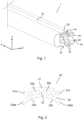
- Fig. 1 shows an isometric view of the inventive load carrying bar 1 for a roof rack (not shown), which has an extension in a longitudinal direction X.
- the load carrying bar 1 further has a height in a height direction Y, which direction is a transverse direction relative the longitudinal direction X, and further a width in a width direction Z, which direction is a transverse direction relative the longitudinal and height directions X, Y.
- the load carrying bar 1 comprises at least one channel 10, but the preferred embodiment of Fig.1 has three channels 10, which each is arranged to receive an accessory, or an engagement means for an accessory, which may be inserted through an opening 14 of the channel 10.
- the accessory may be for example a holder, a stop, a lamp, a box etc.
- the channel 10 also has an extension in the longitudinal direction X, preferably along the whole length of the load carrying bar 1.
- the load carrying bar 1 preferably is an aluminium profile made of extruded aluminium.
- each one of the three channels 10 has an opening 14, wherein one channel 10 has the opening 14 directed upwards relating to if the load carrying bar 1 has an orientation as in the figure, the opposite channel 10 has the opening 14 directed downwards and the third channel 10 has the opening 14 directed to the side.
- the load carrying bar 1 further comprises at least one seal 20 (preferably one seal per channel) which comprises a sealing part 21, arranged to cover/seal the opening 14, and a spring part 22, arranged to spring/bias the sealing part 21 towards the opening 14.
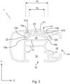
- Fig. 2 shows a cross-section view of the seal 20 which is also visible in Fig.1 , where the seal 20 is arranged into the channel 10 which is directed with its opening 14 upwards.
- the seal 20 has an extension in the longitudinal direction X, and preferably has a length which is similar or close to similar with the length of the channel 10, in the longitudinal direction X.
- the seal 20 comprises the sealing part 21, which is arranged to cover/seal the opening 14, and one spring part 22, which is arranged to spring the sealing part 21 towards the opening 14.
- the seal 20 further comprises one stem part 23, which connects the spring part 22 to the sealing part 21, preferably in the middle of the seal, seen in the width direction Z.
- the stem part 23 has an extension in the height direction Y, which means that two cavities 25a, 25b are formed/arranged between the sealing part 21 and the spring part 22 on opposite sides of the stem part 23, such that the sealing part 21 and spring part 22 are arranged with a distance between them, as seen in Fig. 2 .
- the seal 20 is made of elastic material, which preferably is a "foam-like", soft material which differs from known seals for load carrying bars, which are made of rather stiff rubber.
- the material of the seal 20 preferably has a density within the range 400 - 900 kg/m 3 , which makes the seal 20 rather soft, wherein an accessory inserted into the channel 10, only gives a local compression of the seal 20, just around the accessory, very local around the same. More preferred, the density is between 550 - 750 kg/m 3 and even more preferred, around 650 kg/m 3 which is proven optional features of the seal 20 together with the overall design of the seal 20.
- the sealing part 21 of the seal 20 comprises a first engagement part 21a arranged to engage with a first flange 13a of the load carrying bar 1 and a second engagement part 21b arranged to engage with a second flange 13b of the load carrying bar 1 (see description in connection to Fig. 3 ).
- the first and second engagement parts 21a, 21b are arranged to prevent the seal 20 from leaving the channel 10 when the spring part 22 springs the sealing part 21 towards the opening 14.
- the spring part 22 is C-shaped (or U-shaped) and comprises a first shank 22a and an opposite second shank 22b which each is attached to the stem part 23, wherein the first shank 22a comprises a first free end 22aa and the second shank 22b comprises a second free end 22bb. Another way to describe it is that the C-shaped spring part 22 is connected in the middle to the stem part 23, where the first and second shanks 22a, 22b extends away from the stem part 23 on opposite sides of the same.
- Fig. 3 shows a cross-section view of the load carrying bar 1 of Fig. 1 .
- the channel 10 comprises a bottom part 11 and two opposite sidewalls 12a, 12b, and the first and second flanges 13a, 13b.
- the first flange 13a protrudes from the first sidewall 12a, at a distance from the bottom part 11, i.e. near an outer side of the load carrying bar 1, and the first flange 13a protrudes in direction towards the second sidewall 12b.
- the second flange 13b protrudes from the second sidewall 12b, distal from the bottom part 11, in direction towards the first sidewall 12a.
- the opening 14 is defined between the first and second flanges 13a, 13b.
- the channel 10 has a first width w 1 , between the first and second sidewalls 12a, 12b (in the width direction Z) and the opening 14 has a second width w 2 , between the first and second flanges 13a, 13b (in the width direction Z).
- the second width w 2 of the opening 11 is smaller than the first width w 1 of the channel 10, wherein accessories may be fitted into the channel 10 and further be locked there in optionable ways, normally by engagement between the engagement means of the accessory and channel parts as the sidewalls 12a, 12b, the flanges 13a, 13b and maybe the bottom part 11.
- the spring part 22 of the seal 20 is as mentioned arranged in contact with at least the bottom part 11, but more preferred, in contact with first and second corners 15a, 15b of the channel 10.
- the first corner 15a is arranged between the first sidewall 12a and the bottom part 11 of the channel 10 and the second corner 15b is arranged between the second sidewall 12b and the bottom part 11 of the channel 10.
- the first free end 22aa of the first shank 22a is arranged to engage with the first corner 15a of the channel 10
- the second free end 22bb of the second shank 22b is arranged to engage with the second corner 15b of the channel 10, which may be seen in Fig.3 .
- the channel 10 Since there is a problem with disturbing noise when wind passing the channel 10, when a vehicle arranged with the load carrying bar 1 is traveling ahead, the channel 10 must be covered as much as possible.
- the design of the seal 20 solves this in a very good way, wherein the sealing part 21 covers the opening 14 in a very smooth way, and the first engagement part 21a engages with the first flange 13a of the load carrying bar 1 and the second engagement part 21b engages with the second flange 13b of the load carrying bar 1, as mentioned above, wherein a good sealing function is achieved around the flanges 13a, 13b and of the opening 14.
- the first and second engagement parts 21a, 21b further prevent the seal 20 from leaving the channel 10 when the spring part 22 springs the sealing part 21 towards the opening 14.
- the side channel 10 is designed such that the bottom part 11 comprises two shelf parts 11 arranged on opposite sides of a floor part 11, which shelf parts and floor part are parts of the bottom part 11.
- the first free end 22aa of the first shank 22a is arranged to engage with the first corner 15a, which is the corner between one of the shelf parts 11 and the first sidewall 12a and the second free end 22bb of the second shank 22b is arranged to engage with the second corner 15b, which is the corner between the other of the shelf parts 11 and the second sidewall 12b.
Landscapes
- Engineering & Computer Science (AREA)
- Mechanical Engineering (AREA)
- Specific Sealing Or Ventilating Devices For Doors And Windows (AREA)
- Sealing Devices (AREA)
- Fittings On The Vehicle Exterior For Carrying Loads, And Devices For Holding Or Mounting Articles (AREA)
Applications Claiming Priority (1)
| Application Number | Priority Date | Filing Date | Title |
|---|---|---|---|
| SE2350381A SE546609C2 (en) | 2023-03-31 | 2023-03-31 | Load carrying bar with seal |
Publications (3)
| Publication Number | Publication Date |
|---|---|
| EP4438413A1 true EP4438413A1 (fr) | 2024-10-02 |
| EP4438413B1 EP4438413B1 (fr) | 2025-12-17 |
| EP4438413C0 EP4438413C0 (fr) | 2025-12-17 |
Family
ID=90366457
Family Applications (1)
| Application Number | Title | Priority Date | Filing Date |
|---|---|---|---|
| EP24164053.1A Active EP4438413B1 (fr) | 2023-03-31 | 2024-03-18 | Barre de support de charge avec joint d'étanchéité |
Country Status (2)
| Country | Link |
|---|---|
| EP (1) | EP4438413B1 (fr) |
| SE (1) | SE546609C2 (fr) |
Citations (6)
| Publication number | Priority date | Publication date | Assignee | Title |
|---|---|---|---|---|
| US6176404B1 (en) | 1998-06-19 | 2001-01-23 | Automaxi Industries | Seal adapted to cover the longitudinal groove in a roof bar |
| AU2006100386A4 (en) * | 2006-04-04 | 2006-06-08 | Hubco Automotive Limited | Roof rack crossbar |
| WO2014022435A1 (fr) * | 2012-07-30 | 2014-02-06 | Yakima Innovation Development Corporation | Élément de remplissage de barre transversale à fentes en t |
| EP2200867B1 (fr) * | 2007-09-21 | 2014-06-18 | Hubco Automotive Ltd | Élément de remplissage souple |
| EP3192702A1 (fr) * | 2013-05-13 | 2017-07-19 | Thule Sweden AB | Barre de support de charge |
| EP3470271A1 (fr) * | 2017-10-16 | 2019-04-17 | Thule Sweden AB | Support de charge |
Family Cites Families (1)
| Publication number | Priority date | Publication date | Assignee | Title |
|---|---|---|---|---|
| EP4140818B1 (fr) * | 2018-07-02 | 2024-02-14 | Thule Sweden AB | Support de charge |
-
2023
- 2023-03-31 SE SE2350381A patent/SE546609C2/en unknown
-
2024
- 2024-03-18 EP EP24164053.1A patent/EP4438413B1/fr active Active
Patent Citations (7)
| Publication number | Priority date | Publication date | Assignee | Title |
|---|---|---|---|---|
| US6176404B1 (en) | 1998-06-19 | 2001-01-23 | Automaxi Industries | Seal adapted to cover the longitudinal groove in a roof bar |
| AU2006100386A4 (en) * | 2006-04-04 | 2006-06-08 | Hubco Automotive Limited | Roof rack crossbar |
| EP2200867B1 (fr) * | 2007-09-21 | 2014-06-18 | Hubco Automotive Ltd | Élément de remplissage souple |
| WO2014022435A1 (fr) * | 2012-07-30 | 2014-02-06 | Yakima Innovation Development Corporation | Élément de remplissage de barre transversale à fentes en t |
| EP3192702A1 (fr) * | 2013-05-13 | 2017-07-19 | Thule Sweden AB | Barre de support de charge |
| EP3192702B1 (fr) | 2013-05-13 | 2018-08-22 | Thule Sweden AB | Barre de support de charge |
| EP3470271A1 (fr) * | 2017-10-16 | 2019-04-17 | Thule Sweden AB | Support de charge |
Also Published As
| Publication number | Publication date |
|---|---|
| EP4438413B1 (fr) | 2025-12-17 |
| SE2350381A1 (en) | 2024-10-01 |
| SE546609C2 (en) | 2025-01-02 |
| EP4438413C0 (fr) | 2025-12-17 |
Similar Documents
| Publication | Publication Date | Title |
|---|---|---|
| US8286924B2 (en) | Clip | |
| US11279294B2 (en) | Assemblies for supporting a load relative to a roof of a vehicle | |
| US8772636B2 (en) | Wire harness installation structure and wire harness-flattening band | |
| US8042776B2 (en) | Adjustable mounting bracket | |
| CN107415843B (zh) | 承重条 | |
| US7297871B2 (en) | Electric supply apparatus | |
| US6543957B1 (en) | Holder and housing comprising at least one holder | |
| US20120132465A1 (en) | Wire harness arrangement structure | |
| KR102570183B1 (ko) | 케이블 관리용 브라켓 | |
| US11542970B2 (en) | Edge protector | |
| EP1909363A2 (fr) | Support de câble et procédé de support de câble | |
| US5857799A (en) | Base channel connector clip | |
| JP4358640B2 (ja) | 導線ホルダ | |
| EP4438413A1 (fr) | Barre de support de charge avec joint d'étanchéité | |
| US7105748B2 (en) | Door module for a vehicle | |
| ES2539949T3 (es) | Conector eléctrico que tiene una palanca con escudo protector | |
| KR20140070578A (ko) | 와이퍼 블레이드의 패키징 장치 | |
| US6747208B2 (en) | Slack absorber of wire harness | |
| US20100230426A1 (en) | Protective caps for wiper blades | |
| AU2003200871B2 (en) | Connector holder | |
| US12107401B2 (en) | Wiring harness module and wiring harness routing device | |
| US20040014353A1 (en) | Clamping spring device for an elastic clamp | |
| US6083042A (en) | Adjustable connecting device | |
| FR2815184A1 (fr) | Plaquettes encliquetables pour chemins a cables en treillis de fils, montage de telles plaquettes sur des chemins a cables | |
| KR100804262B1 (ko) | 커넥터용 프론트홀더의 록킹구조 |
Legal Events
| Date | Code | Title | Description |
|---|---|---|---|
| PUAI | Public reference made under article 153(3) epc to a published international application that has entered the european phase |
Free format text: ORIGINAL CODE: 0009012 |
|
| STAA | Information on the status of an ep patent application or granted ep patent |
Free format text: STATUS: THE APPLICATION HAS BEEN PUBLISHED |
|
| AK | Designated contracting states |
Kind code of ref document: A1 Designated state(s): AL AT BE BG CH CY CZ DE DK EE ES FI FR GB GR HR HU IE IS IT LI LT LU LV MC ME MK MT NL NO PL PT RO RS SE SI SK SM TR |
|
| STAA | Information on the status of an ep patent application or granted ep patent |
Free format text: STATUS: REQUEST FOR EXAMINATION WAS MADE |
|
| 17P | Request for examination filed |
Effective date: 20250319 |
|
| GRAP | Despatch of communication of intention to grant a patent |
Free format text: ORIGINAL CODE: EPIDOSNIGR1 |
|
| STAA | Information on the status of an ep patent application or granted ep patent |
Free format text: STATUS: GRANT OF PATENT IS INTENDED |
|
| RIC1 | Information provided on ipc code assigned before grant |
Ipc: B60R 9/04 20060101AFI20250630BHEP Ipc: B60R 9/052 20060101ALI20250630BHEP |
|
| INTG | Intention to grant announced |
Effective date: 20250722 |
|
| GRAS | Grant fee paid |
Free format text: ORIGINAL CODE: EPIDOSNIGR3 |
|
| GRAA | (expected) grant |
Free format text: ORIGINAL CODE: 0009210 |
|
| STAA | Information on the status of an ep patent application or granted ep patent |
Free format text: STATUS: THE PATENT HAS BEEN GRANTED |
|
| AK | Designated contracting states |
Kind code of ref document: B1 Designated state(s): AL AT BE BG CH CY CZ DE DK EE ES FI FR GB GR HR HU IE IS IT LI LT LU LV MC ME MK MT NL NO PL PT RO RS SE SI SK SM TR |
|
| REG | Reference to a national code |
Ref country code: CH Ref legal event code: F10 Free format text: ST27 STATUS EVENT CODE: U-0-0-F10-F00 (AS PROVIDED BY THE NATIONAL OFFICE) Effective date: 20251217 Ref country code: GB Ref legal event code: FG4D |
|
| REG | Reference to a national code |
Ref country code: DE Ref legal event code: R096 Ref document number: 602024001681 Country of ref document: DE |
|
| U01 | Request for unitary effect filed |
Effective date: 20251217 |
|
| U07 | Unitary effect registered |
Designated state(s): AT BE BG DE DK EE FI FR IT LT LU LV MT NL PT RO SE SI Effective date: 20251223 |
|
| PG25 | Lapsed in a contracting state [announced via postgrant information from national office to epo] |
Ref country code: NO Free format text: LAPSE BECAUSE OF FAILURE TO SUBMIT A TRANSLATION OF THE DESCRIPTION OR TO PAY THE FEE WITHIN THE PRESCRIBED TIME-LIMIT Effective date: 20260317 |
|
| PG25 | Lapsed in a contracting state [announced via postgrant information from national office to epo] |
Ref country code: HR Free format text: LAPSE BECAUSE OF FAILURE TO SUBMIT A TRANSLATION OF THE DESCRIPTION OR TO PAY THE FEE WITHIN THE PRESCRIBED TIME-LIMIT Effective date: 20251217 |
|
| U20 | Renewal fee for the european patent with unitary effect paid |
Year of fee payment: 3 Effective date: 20260311 |
|
| PG25 | Lapsed in a contracting state [announced via postgrant information from national office to epo] |
Ref country code: RS Free format text: LAPSE BECAUSE OF FAILURE TO SUBMIT A TRANSLATION OF THE DESCRIPTION OR TO PAY THE FEE WITHIN THE PRESCRIBED TIME-LIMIT Effective date: 20260317 |