EP4438486A1 - Ensemble propulsif pour aéronef comportant un turboréacteur, un mât et des moyens d accrochage du turboréacteur au mât - Google Patents
Ensemble propulsif pour aéronef comportant un turboréacteur, un mât et des moyens d accrochage du turboréacteur au mât Download PDFInfo
- Publication number
- EP4438486A1 EP4438486A1 EP24166214.7A EP24166214A EP4438486A1 EP 4438486 A1 EP4438486 A1 EP 4438486A1 EP 24166214 A EP24166214 A EP 24166214A EP 4438486 A1 EP4438486 A1 EP 4438486A1
- Authority
- EP
- European Patent Office
- Prior art keywords
- casing
- axis
- propulsion assembly
- median plane
- rigid structure
- Prior art date
- Legal status (The legal status is an assumption and is not a legal conclusion. Google has not performed a legal analysis and makes no representation as to the accuracy of the status listed.)
- Granted
Links
Images


Classifications
-
- B—PERFORMING OPERATIONS; TRANSPORTING
- B64—AIRCRAFT; AVIATION; COSMONAUTICS
- B64D—EQUIPMENT FOR FITTING IN OR TO AIRCRAFT; FLIGHT SUITS; PARACHUTES; ARRANGEMENT OR MOUNTING OF POWER PLANTS OR PROPULSION TRANSMISSIONS IN AIRCRAFT
- B64D27/00—Arrangement or mounting of power plants in aircraft; Aircraft characterised by the type or position of power plants
- B64D27/02—Aircraft characterised by the type or position of power plants
- B64D27/16—Aircraft characterised by the type or position of power plants of jet type
- B64D27/18—Aircraft characterised by the type or position of power plants of jet type within, or attached to, wings
-
- B—PERFORMING OPERATIONS; TRANSPORTING
- B64—AIRCRAFT; AVIATION; COSMONAUTICS
- B64D—EQUIPMENT FOR FITTING IN OR TO AIRCRAFT; FLIGHT SUITS; PARACHUTES; ARRANGEMENT OR MOUNTING OF POWER PLANTS OR PROPULSION TRANSMISSIONS IN AIRCRAFT
- B64D27/00—Arrangement or mounting of power plants in aircraft; Aircraft characterised by the type or position of power plants
- B64D27/40—Arrangements for mounting power plants in aircraft
-
- B—PERFORMING OPERATIONS; TRANSPORTING
- B64—AIRCRAFT; AVIATION; COSMONAUTICS
- B64D—EQUIPMENT FOR FITTING IN OR TO AIRCRAFT; FLIGHT SUITS; PARACHUTES; ARRANGEMENT OR MOUNTING OF POWER PLANTS OR PROPULSION TRANSMISSIONS IN AIRCRAFT
- B64D27/00—Arrangement or mounting of power plants in aircraft; Aircraft characterised by the type or position of power plants
- B64D27/40—Arrangements for mounting power plants in aircraft
- B64D27/402—Arrangements for mounting power plants in aircraft comprising box like supporting frames, e.g. pylons or arrangements for embracing the power plant
-
- B—PERFORMING OPERATIONS; TRANSPORTING
- B64—AIRCRAFT; AVIATION; COSMONAUTICS
- B64D—EQUIPMENT FOR FITTING IN OR TO AIRCRAFT; FLIGHT SUITS; PARACHUTES; ARRANGEMENT OR MOUNTING OF POWER PLANTS OR PROPULSION TRANSMISSIONS IN AIRCRAFT
- B64D27/00—Arrangement or mounting of power plants in aircraft; Aircraft characterised by the type or position of power plants
- B64D27/40—Arrangements for mounting power plants in aircraft
- B64D27/404—Suspension arrangements specially adapted for supporting vertical loads
-
- B—PERFORMING OPERATIONS; TRANSPORTING
- B64—AIRCRAFT; AVIATION; COSMONAUTICS
- B64D—EQUIPMENT FOR FITTING IN OR TO AIRCRAFT; FLIGHT SUITS; PARACHUTES; ARRANGEMENT OR MOUNTING OF POWER PLANTS OR PROPULSION TRANSMISSIONS IN AIRCRAFT
- B64D27/00—Arrangement or mounting of power plants in aircraft; Aircraft characterised by the type or position of power plants
- B64D27/40—Arrangements for mounting power plants in aircraft
- B64D27/406—Suspension arrangements specially adapted for supporting thrust loads, e.g. thrust links
Definitions
- the present invention relates to the general field of attaching a turbojet engine under the wing of an aircraft. It relates in particular to a propulsion unit comprising a turbojet engine, in particular a dual-flow turbojet engine, a mast and a attachment device intended for attaching the turbojet engine under the mast. It also relates to an aircraft equipped with such a propulsion unit.
- a propulsion unit of the state of the art is fixed under a wing of an aircraft which comprises a turbojet engine and a mounting pylon by means of which the turbojet engine is fixed under the wing.
- the mounting pylon comprises a rigid structure, also called a primary structure, carrying first fixing elements intended for attaching the turbojet engine.
- These first fixing elements are formed of a front engine attachment, a rear engine attachment, and a device for absorbing the thrust forces generated by the turbojet.
- the attachment mast further comprises second fixing elements allowing the attachment mast to be fixed to the sail.
- the turbojet engine has at the front a fan casing surrounding an annular fan duct, and towards the rear a central casing of smaller dimensions, enclosing the core of the turbojet engine.
- the front engine attachment is interposed between a front end of the rigid structure and an upper and front part of the central casing called “core casing" in English and the rear engine attachment is interposed between the rigid structure and an upper and rear part of the same central casing.
- the device for taking up the thrust forces generated by the turbojet engine comprises two connecting rods arranged on either side of a median vertical plane of the turbojet engine and articulated, on the one hand, on the central casing, and, on the other hand, on a single rudder fixed to the rigid structure.
- the device for thrust force recovery which is formed by the two connecting rods and the rudder is designed to absorb all or the majority of the forces oriented in the longitudinal direction X of the turbojet.
- the front engine mount has a connecting rod on either side of the mast, and each connecting rod is hingedly attached by one end thereof to the mast and is hingedly attached by the other end thereof to the central crankcase.
- One of the connecting rods is attached by two connection points to the mast and by one connection point to the central crankcase, and the second connecting rod is attached by one connection point to the mast and by one connection point to the central crankcase.
- the front engine mount allows to absorb, in its plane, part of the forces oriented in the Y and Z directions as well as a torsional moment Mx.
- the rear engine mount includes a triangular shackle which is fixed in an articulated manner by one of its upper ends to the mast and is fixed in an articulated manner by one of its lower ends to the engine.
- This triangular shackle is therefore composed of an upper connection point on the mast side and positioned on the median plane of the mast under its lower wall and two lower points on the engine side and positioned on either side of the median plane of the mast on the engine casing.
- Such an arrangement also allows to absorb, in its plane, part of the forces oriented in the Y and Z directions.
- An object of the present invention is to provide a propulsion assembly comprising a turbojet, a mast and a hooking device intended for hooking the turbojet under the mast with reduced bulk.
- each lateral fixing point provides a pivot connection whose axis crosses the longitudinal axis and is perpendicular to a tangent to the casing at the point of intersection between the axis and the casing.
- each articulation between a connecting rod and the front fitting takes the form of a pivot connection whose axis is generally parallel to the axis of the pivot connection of the lateral fixing point which is on the same side.
- the propulsion assembly comprises a front bar arranged in the upper part of the turbojet and in the median plane and mounted articulated between a front part of the rigid structure and a front part of the intermediate casing.
- the propulsion assembly comprises a shear pin with a first end secured to the front fitting and projecting a second end forward and whose axis is parallel to the longitudinal axis, where the axis of the shear pin is in the median plane, and a housing made in the intermediate casing and in the form of a hole whose axis is parallel to the longitudinal axis and which is arranged to receive the second end of the shear pin.
- the hole is oblong with a large vertical axis and a small horizontal axis.
- the propulsion assembly comprises a rear engine attachment comprising two shackles with two fixing points arranged symmetrically on either side of the median plane, where each shackle is mounted articulated between a shoe of the rigid structure and a tab of the casing.
- the propulsion assembly comprises a shear pin with a first end secured to the front fitting and projecting a second end forward and whose axis is parallel to the longitudinal axis, where the axis of the shear pin is in the median plane, and a housing made in the intermediate casing and in the form of a hole whose axis is parallel to the longitudinal axis and which is arranged to receive the second end of the shear pin, and the propulsion assembly comprises a rear engine attachment with a shackle with two fixing points, arranged at the median plane, where the shackle is mounted articulated between a shoe of the rigid structure and a tab of the casing.
- the hole is oblong with a large vertical axis and a small horizontal axis.
- the invention also proposes an aircraft comprising a wing and a propulsion unit according to one of the preceding variants, the rigid structure of which is fixed under the wing.
- FIG. 1 shows an aircraft 50 which has a wing 52 under which is mounted a propulsion unit 100 according to the invention and which comprises a turbojet 102 housed here in a nacelle and a mounting mast 104.
- X is called the longitudinal axis of the turbojet 102, this axis X being parallel to a longitudinal direction of this turbojet 102.
- Y is called the transverse axis of the turbojet 102 which is horizontal when the aircraft is on the ground
- Z is called the axis vertical or vertical height when the aircraft is on the ground, these three axes X, Y and Z being orthogonal to each other.
- front and rear are to be considered in relation to a direction of advancement of the aircraft 50 during operation of the turbojet 102, this direction being represented schematically by the arrow 107.
- the attachment mast 104 is generally symmetrical with respect to a vertical median plane XZ of the turbojet engine 102 which passes through the longitudinal axis X of the turbojet engine 102 and which is subsequently called the median plane P.
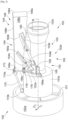
- FIG. 2 shows the propulsion assembly 100 which comprises the turbojet 102 and the attachment mast 104 by which the turbojet 102 is fixed to the wing 52 (not shown in the Fig. 2 ).
- the attachment mast 104 is here represented by its rigid structure 106, also called primary structure, carrying fixing elements 150 intended for attaching the turbojet 102 under the rigid structure 106.
- the rigid structure 106 extends along the longitudinal axis X between a front end and a rear end between which there is a median zone.
- the rigid structure 106 takes the form of a box which comprises a lower wall 106a, an upper wall 106b, two side walls 106c-d on either side of the median plane P and a front wall 106e oriented forward.
- the rigid structure 106 is fixed to the wing 52 by a fixing system which is not shown, because it is outside the scope of the invention and can take any form known to those skilled in the art.
- the turbojet 102 comprises from front to rear, a fan casing 102a in which is mounted a fan materializing a rotor and a stator 102b which comprises a casing 103 in which are successively housed compression stages, a combustion chamber, turbine stages and an ejection nozzle.
- the air flow which enters through the fan casing 102a is divided into a primary flow which flows in the stator 102b and a secondary flow which flows around the stator 102b.
- the casing 103 is made up from front to rear of an intermediate casing 103a, a central casing 103b and a rear casing 103c which are integral with each other.
- the central casing 103b are housed the compression stages and the combustion chamber while the rear casing 103c accommodates the turbine stages.
- the intermediate casing 103a is arranged between the fan casing 102a and the central casing 103b and it is secured to said fan casing 102a by any suitable fixing means such as radial arms 101.
- the central casing 103b extends to the rear of the intermediate casing 103a and has a smaller diameter which makes it possible to expose a rear face 105 of the intermediate casing 103a which here extends in a generally vertical plane YZ, that is to say perpendicular to the longitudinal axis X.
- the fastening elements 150 comprise a front engine attachment 152 and an intermediate engine attachment 154.
- the Fig. 3 shows the fastening elements 150 without the turbojet 102.
- the front engine attachment 152 comprises a front fitting 152a which takes the form of a horseshoe which is positioned around and above the central casing 103b, in particular above the upper half-sector of the front zone of the central casing 103b, and at the rear of the intermediate casing 103a.
- the front fitting 152a is fixed in an articulated manner by two lateral fixing points 156a-b to the intermediate casing 103a and more particularly to its rear face 105 and in a rigid manner by an upper fixing zone 156c to the rigid structure 106 and more particularly to the front wall 106e. A portion of the front fitting 152a is thus pressed against and fixed against the front wall 106e.
- the upper fixing zone 156c is arranged in the upper part at the level of the median plane P and the lateral fixing points 156a-b are arranged on either side of the median plane P.
- the upper fixing zone 156c ensures a complete connection or embedding between the front fitting 152a and the rigid structure 106.
- the fixing is carried out for example using screw elements, rivets, or others over the entire periphery of the front wall 106e in connection with the lower 106a, upper 106b and side 106c-d walls of the rigid structure 106.
- Each lateral attachment point 156a-b provides a pivot connection about a direction of articulation between the front fitting 152a and the rear face 105 of the intermediate casing 103a.
- Each pivot connection is produced here by a female yoke secured to the rear face 105 of the intermediate casing 103a and a male yoke secured to the front fitting 152a and fitted into the female yoke and by an axis which passes through the female yoke and fits into the male yoke.
- each lateral attachment point 156a-b is here generally at the same height as the longitudinal axis X and, seen from behind, the axis of each pivot connection is oriented at approximately 45° relative to the transverse axis Y, clockwise for the lateral attachment point 156a on the port side and counterclockwise for the lateral attachment point 156b on the starboard side.
- the direction of the axis varies from 10° to 90° relative to the vertical axis Z depending on the azimuthal position of the lateral fixing points 156a-b and preferably, the axis crosses the longitudinal axis X and is perpendicular to the tangent to the casing 103 at the point of intersection between the axis and the casing 103, and in other words, the axis is perpendicular to the plane defined by the lateral fixing point 156a-b and the connecting rods 154a-b which are on the same side.
- the intermediate engine attachment 154 which constitutes a device for taking up the thrust forces of the turbojet 102 comprises two pairs of connecting rods 154a-b, where each pair is arranged on one side of the median plane P and articulated, on the one hand, at the front on the front fitting 152a, and, on the other hand, at the rear on the rigid structure 106 at the median zone, and more particularly on the side wall 106c-d which is on the same side.
- Each pair of connecting rods 154a-b comprises a front connecting rod 154a and a rear connecting rod 154b and each is hingedly mounted at the front on the front bracket 152a and at the rear on the side wall 106c-d.
- the front fitting 152a comprises for each pair of connecting rods 154a-b, an extension 158 which extends towards the rear of each lateral fixing point 156a-b and on which each connecting rod 154a-b is mounted articulated around a pivot connection.
- the intermediate engine attachment 154 comprises for each connecting rod 154a-b, a fitting 160a-b rigidly fixed to the side wall 106c-d considered and on which said connecting rod 154a-b is mounted articulated around a pivot connection.
- each end of a connecting rod 154a-b has a female yoke in which is fitted a male yoke consisting respectively of a part of the extension 158 or of a part of the respective fitting 160a-b and where an axis passes through the female yoke and fits into the male yoke.
- Each axis of the pivot connection corresponding to an extension 158 is generally parallel to the axis of the pivot connection of the lateral fixing point 156a-b which is on the same side.
- the bulk of the front engine mount is reduced in the secondary flow and induces less aerodynamic protuberance at the secondary flow cowling.
- Each lateral fixing point 156a-b allows forces to be taken up in two directions, mainly oriented along the Z and X axes.
- the propulsion assembly 100 comprises a front bar 170 which is mounted articulated between the rigid structure 106 and the intermediate casing 103a.
- the front bar 170 is arranged in the upper part of the turbojet 102 and in the median plane P.
- the front bar 170 may be in the form of a connecting rod or a shackle.
- the front bar 170 is more particularly mounted articulated between a front part of the rigid structure 106, here the front part of the upper wall 106b, and a front part of the intermediate casing 103a.
- Each articulation of the front bar 170 to the rigid structure 106 and to the intermediate casing 103a here takes the form of a pivot connection whose axis and is parallel to the transverse axis Y.
- the front bar 170 ensures the absorption of forces in a direction mainly oriented along the axis X and in combination with the lateral fixing points 156a-b, absorbs the bending moment My.
- each pivot connection is produced here by a female yoke secured to one end of the front bar 170 and respectively to a first male yoke 170a secured to the rigid structure 106 or to a second male yoke 170b secured to the intermediate casing 103a, and where an axis passes through the female yoke and fits into the male yoke 170a-b parallel to the transverse axis Y.
- the first male yoke 170a is rigidly fixed to the upper wall 106b by means of an L-shaped angle iron 172 and to the front fitting 152a by any suitable means such as screw elements, rivets, weld points, etc.
- the propulsion assembly 100 further comprises a shear pin 176 (also called a “spigot”) which is cylindrical, which has a first end secured to the front fitting 152a and which projects a second end forward and whose axis is parallel to the longitudinal axis X.
- the axis of the shear pin 176 is in the median plane P.
- the propulsion assembly 100 also includes a housing 178 made in the intermediate casing 103a and more particularly here in the rear face 105.
- the housing 178 takes the form of a hole 179 whose axis is parallel to the longitudinal axis X and which is arranged to receive the second end of the shear pin 176.
- the hole 179 is oblong with a large vertical axis, i.e. parallel to the vertical axis Z, and a small horizontal axis, i.e. parallel to the transverse axis Y, where the width of the hole 179 is adapted to the diameter of the shear pin 176 to ensure a 'fitted' sliding contact with the shear pin 176.
- the housing 178 and the shear pin 176 are thus free to rotate relative to each other and free to translate vertically relative to each other.
- the shear pin 176 ensures the absorption of forces in a direction oriented along the transverse axis Y. This gives an assembly said to be adjusted without play along the transverse axis Y and not adjusted with play along the vertical axis Z.
- the front bar 170 and the shear pin 176 are replaced by a rear engine attachment 180 which is mounted articulated between the rigid structure 106, and more particularly here the lower wall 106a, and the casing 103, and more particularly here the central casing 103b.
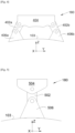
- FIG. 4 An example of a 180 rear engine mount is shown in Fig. 4
- the rear engine attachment 180 comprises two shackles 402a-b with two fixing points and they are arranged symmetrically on either side of the median plane P.
- Each shackle 402a-b is mounted articulated between a shoe 404 of the rigid structure 106, and more particularly of the lower wall 106a, and a tab 406a-b of the casing 103 and more particularly of the central casing 103b.
- Each articulation takes the form of a pivot connection whose axis is parallel to the longitudinal axis X and it is produced for example in the form of a connection of the yoke type.
- Such a rear engine attachment 180 ensures the absorption of forces in two directions mainly oriented along the axes Z and Y and in combination with the front engine attachment plane, absorbs the bending moment My.
- the shear pin 176 is retained and the front bar 170 is replaced by a rear engine attachment 180 which is mounted articulated between the rigid structure 106, and more particularly here the lower wall 106a, and the casing 103, and more particularly here the central casing 103b. This maintains the assembly called adjusted without play along the transverse axis Y and not adjusted with play along the vertical axis Z.
- FIG. 5 An example of a 180 rear engine mount is shown in Fig. 5 .
- the rear engine attachment 180 comprises a shackle 502 with two fixing points which is arranged at the level of the median plane P.
- the shackle 502 is mounted articulated between a shoe 504 of the rigid structure 106, and more particularly of the lower wall 106a, and a tab 506 of the casing 103 and more particularly of the central casing 103b.
- Each articulation takes the form of a pivot connection whose axis is parallel to the longitudinal axis X and it is produced for example in the form of a connection of the yoke type.
- Such a rear engine attachment 180 ensures the absorption of forces in a direction oriented along the vertical axis Z, in combination with the front engine attachment plane, absorbs the bending moment My.
- the interface system between the engine and the reactor mast is said to be "isostatic”, that is to say that all six degrees of freedom (3 translations / 3 rotations) are blocked and allow an "efficient and robust" transfer of forces and moments.
- the positioning of the two lateral fixing points 156a-b and the span of the fitting 152a are here proposed on an angular sector between 10 o'clock and 2 o'clock. However, these elements can be proposed on an angular sector between 9 o'clock and 3 o'clock without changing the scope of the invention.
- the positioning of the two lateral fixing points 156a-b can be arranged radially over the entire rear face 105, that is to say between the internal diameter and the external diameter.
Landscapes
- Engineering & Computer Science (AREA)
- Aviation & Aerospace Engineering (AREA)
- Pivots And Pivotal Connections (AREA)
- Structures Of Non-Positive Displacement Pumps (AREA)
Abstract
Description
- La présente invention se rapporte au domaine général de l'accrochage d'un turboréacteur sous la voilure d'un aéronef. Elle concerne en particulier un ensemble propulsif comprenant un turboréacteur, en particulier à double flux, un mât ainsi qu'un dispositif d'accrochage destiné à l'accrochage du turboréacteur sous le mât. Elle concerne également un aéronef équipé d'un tel ensemble propulsif.
- Un ensemble propulsif de l'état de la technique est fixé sous une voilure d'un aéronef qui comporte un turboréacteur et un mât d'accrochage par l'intermédiaire duquel le turboréacteur est fixé sous la voilure. Globalement, le mât d'accrochage comporte une structure rigide, également appelée structure primaire, portant des premiers éléments de fixation destinés à l'accrochage du turboréacteur.
- Ces premiers éléments de fixation sont formés d'une attache moteur avant, d'une attache moteur arrière, et d'un dispositif de reprise des efforts de poussée générés par le turboréacteur.
- Le mât d'accrochage comporte en outre des seconds éléments de fixation permettant la fixation du mât d'accrochage à la voilure.
- Le turboréacteur comporte à l'avant un carter de soufflante entourant un canal annulaire de soufflante, et vers l'arrière un carter central de plus petite dimension, renfermant le coeur du turboréacteur.
- Dans le cas d'une architecture de mât réacteur dite « Core », l'attache moteur avant est interposée entre une extrémité avant de la structure rigide et une partie supérieure et avant du carter central dit « core casing » en anglais et l'attache moteur arrière est interposée entre la structure rigide et une partie supérieure et arrière du même carter central. Le dispositif de reprise des efforts de poussée générés par le turboréacteur comprend deux bielles disposées de part et d'autre d'un plan vertical médian du turboréacteur et articulées, d'une part, sur le carter central, et, d'autre part, sur un palonnier unique fixé à la structure rigide. Le dispositif de reprise des efforts de poussée qui est formé par les deux bielles et le palonnier est conçu pour reprendre l'intégralité ou la majorité des efforts orientés selon la direction longitudinale X du turboréacteur.
- L'attache moteur avant comporte de part et d'autre du mât une bielle, et chaque bielle est fixée de manière articulée par une de ses extrémités au mât et est fixée de manière articulée par l'autre de ses extrémités au carter central. L'une des bielles est fixée par deux points de liaison au mât et par un point de liaison au carter central, et la deuxième bielle est fixée par un point de liaison au mât et par un point de liaison au carter central.
- L'attache moteur avant permet de reprendre, en son plan, une partie des efforts orientés selon les directions Y et Z ainsi qu'un moment de torsion Mx. L'attache moteur arrière comporte une manille triangulaire qui est fixée de manière articulée par une de ses extrémités supérieures au mât et est fixée de manière articulée par une de ses extrémités inférieures au moteur. Cette manille triangulaire est donc composée d'un point de liaison supérieur côté mât et positionné sur le plan médian du mât sous sa paroi inférieure et de deux points inférieurs côté moteur et positionnés de part et d'autre du plan médian du mât sur le carter moteur. Un tel arrangement permet également de reprendre, en son plan, une partie des efforts orientés selon les directions Y et Z.
- Bien qu'une telle structure donne satisfaction, il est souhaitable de trouver un arrangement alternatif qui permet une diminution de l'encombrement des attaches moteur, notamment lorsque celles-ci deviennent les éléments de contraintes pour la définition des capotages définissant les formes aérodynamiques aussi bien internes qu'externes de la turbomachine.
- Un objet de la présente invention est de proposer un ensemble propulsif comprenant un turboréacteur, un mât et un dispositif d'accrochage destiné à l'accrochage du turboréacteur sous le mât avec un encombrement réduit.
- À cet effet, est proposé un ensemble propulsif d'un aéronef, ledit ensemble propulsif comportant :
- un turboréacteur comportant un carter présentant de l'avant vers l'arrière, un carter intermédiaire et un carter central autour d'un axe longitudinal et présentant un plan médian vertical passant par l'axe longitudinal, où le carter central s'étend à l'arrière du carter intermédiaire et présente un diamètre inférieur pour dégager une face arrière du carter intermédiaire,
- un mât d'accrochage présentant une structure rigide avec une paroi frontale et deux parois latérales de part et d'autre du plan médian,
- une attache moteur avant comportant une ferrure avant positionnée autour et au-dessus du carter central et à l'arrière du carter intermédiaire, où la ferrure avant est fixée de manière articulée par deux points latéraux de fixation à la face arrière et de manière rigide par une zone supérieure de fixation à la paroi frontale, où la zone supérieure de fixation est disposée en partie haute au niveau du plan médian, et où les points latéraux de fixation sont disposés de part et d'autre du plan médian, et
- une attache moteur intermédiaire comprenant deux paires de bielles où chaque paire est disposée d'un côté du plan médian et comporte une bielle avant et une bielle arrière où chacune est montée articulée entre la ferrure avant et la paroi latérale de la structure rigide qui est du même côté.
- Avec un tel arrangement, l'encombrement des attaches moteur est réduit dans le flux secondaire.
- Avantageusement, chaque point latéral de fixation assure une liaison pivot dont l'axe croise l'axe longitudinal et est perpendiculaire à une tangente au carter au point d'intersection entre l'axe et le carter.
- Avantageusement, chaque articulation entre une bielle et la ferrure avant prend la forme d'une liaison pivot dont l'axe est globalement parallèle à l'axe de la liaison pivot du point latéral de fixation qui est du même côté.
- Selon un mode de réalisation particulier, l'ensemble propulsif comporte une barre frontale arrangée en partie haute du turboréacteur et dans le plan médian et montée articulée entre une partie avant de la structure rigide et une partie avant du carter intermédiaire. Avantageusement, l'ensemble propulsif comporte un pion de cisaillement avec une première extrémité solidaire de la ferrure avant et projetant une deuxième extrémité vers l'avant et dont l'axe est parallèle à l'axe longitudinal, où l'axe du pion de cisaillement est dans le plan médian, et un logement réalisé dans le carter intermédiaire et sous forme d'un trou dont l'axe est parallèle à l'axe longitudinal et qui est arrangé pour recevoir la deuxième extrémité du pion de cisaillement.
- Avantageusement, le trou est oblong avec un grand axe vertical et un petit axe horizontal. Selon un mode de réalisation particulier, l'ensemble propulsif comporte une attache moteur arrière comportant deux manilles à deux points de fixation disposées symétriquement de part et d'autre du plan médian, où chaque manille est montée articulée entre un sabot de la structure rigide et une languette du carter.
- Selon un mode de réalisation particulier, l'ensemble propulsif comporte un pion de cisaillement avec une première extrémité solidaire de la ferrure avant et projetant une deuxième extrémité vers l'avant et dont l'axe est parallèle à l'axe longitudinal, où l'axe du pion de cisaillement est dans le plan médian, et un logement réalisé dans le carter intermédiaire et sous forme d'un trou dont l'axe est parallèle à l'axe longitudinal et qui est arrangé pour recevoir la deuxième extrémité du pion de cisaillement, et l'ensemble propulsif comporte une attache moteur arrière avec une manille à deux points de fixation, disposée au niveau du plan médian, où la manille est montée articulée entre un sabot de la structure rigide et une languette du carter.
- Avantageusement, le trou est oblong avec un grand axe vertical et un petit axe horizontal. L'invention propose également un aéronef comportant une voilure et un ensemble propulsif selon l'une des variantes précédentes dont la structure rigide est fixée sous la voilure.
- Les caractéristiques de l'invention mentionnées ci-dessus, ainsi que d'autres, apparaîtront plus clairement à la lecture de la description suivante d'un exemple de réalisation, ladite description étant faite en relation avec les dessins joints, parmi lesquels :
- [
Fig. 1 ] représente une vue de côté d'un aéronef selon l'invention, - [
Fig. 2 ] est une vue en perspective d'un ensemble propulsif selon un mode de réalisation de l'invention, - [
Fig. 3 ] est une vue en perspective de l'ensemble propulsif de laFig. 2 sans le turboréacteur selon le mode de réalisation de l'invention, - [
Fig. 4 ] est une vue de face d'un premier exemple d'une attache moteur arrière mise en oeuvre dans l'ensemble propulsif selon une première variante de l'invention, et - [
Fig. 5 ] est une vue de face d'un deuxième exemple d'une attache moteur arrière mise en oeuvre dans l'ensemble propulsif selon une deuxième variante de l'invention. - La
Fig. 1 montre un aéronef 50 qui présente une voilure 52 sous laquelle est monté un ensemble propulsif 100 selon l'invention et qui comporte un turboréacteur 102 logé ici dans une nacelle et un mât d'accrochage 104. - Par convention, on appelle X l'axe longitudinal du turboréacteur 102, cet axe X étant parallèle à une direction longitudinale de ce turboréacteur 102. D'autre part, on appelle Y, l'axe transversal du turboréacteur 102 qui est horizontal lorsque l'aéronef est au sol, et Z, l'axe vertical ou hauteur verticale lorsque l'aéronef est au sol, ces trois axes X, Y et Z étant orthogonaux entre eux.
- D'autre part, les termes " avant " et " arrière " sont à considérer par rapport à une direction d'avancement de l'aéronef 50 lors du fonctionnement du turboréacteur 102, cette direction étant représentée schématiquement par la flèche 107.
- Le mât d'accrochage 104 est globalement symétrique par rapport à un plan médian vertical XZ du turboréacteur 102 qui passe par l'axe longitudinal X du turboréacteur 102 et qui est appelé par la suite plan médian P.
- La
Fig. 2 montre l'ensemble propulsif 100 qui comporte le turboréacteur 102 et le mât d'accrochage 104 par lequel le turboréacteur 102 est fixé à la voilure 52 (non représentée sur laFig. 2 ). Le mât d'accrochage 104 est ici représenté par sa structure rigide 106, également appelée structure primaire, portant des éléments de fixation 150 destinés à l'accrochage du turboréacteur 102 sous la structure rigide 106. La structure rigide 106 s'étend selon l'axe longitudinal X entre une extrémité avant et une extrémité arrière entre lesquelles se trouve une zone médiane. - Dans le mode de réalisation de l'invention présenté sur la
Fig. 2 , la structure rigide 106 prend la forme d'un caisson qui comporte une paroi inférieure 106a, une paroi supérieure 106b, deux parois latérales 106c-d de part et d'autre du plan médian P et une paroi frontale 106e orientée vers l'avant. La structure rigide 106 est fixée à la voilure 52 par un système de fixation qui n'est pas représenté, car il est hors du périmètre de l'invention et peut prendre toutes formes connues par l'homme du métier. - Dans le mode de réalisation de l'invention présenté à la
Fig. 2 , le turboréacteur 102 comporte de l'avant vers l'arrière, un carter de soufflante 102a dans lequel est montée une soufflante matérialisant un rotor et un stator 102b qui comporte un carter 103 dans lequel sont logés successivement des étages de compression, une chambre de combustion, des étages de turbine et une tuyère d'éjection. Le flux d'air qui pénètre par le carter de soufflante 102a est divisé en un flux primaire qui s'écoule dans le stator 102b et un flux secondaire qui s'écoule autour du stator 102b. - Dans le mode de réalisation de l'invention présenté à la
Fig. 2 , le carter 103 est constitué de l'avant vers l'arrière, d'un carter intermédiaire 103a, d'un carter central 103b et d'un carter arrière 103c qui sont solidaires entre eux. Dans le carter central 103b sont logés les étages de compression et la chambre de combustion alors que le carter arrière 103c accueille les étages de turbine. - Le carter intermédiaire 103a est disposé entre le carter de soufflante 102a et le carter central 103b et il est solidaire dudit carter de soufflante 102a par tous moyens de fixation appropriés tels que des bras radiaux 101.
- Le carter central 103b s'étend à l'arrière du carter intermédiaire 103a et présente un diamètre inférieur ce qui permet de dégager une face arrière 105 du carter intermédiaire 103a qui s'étend ici dans un plan globalement vertical YZ, c'est-à-dire perpendiculaire à l'axe longitudinal X.
- Les éléments de fixation 150 comportent une attache moteur avant 152 et une attache moteur intermédiaire 154. La
Fig. 3 montre les éléments de fixation 150 sans le turboréacteur 102. L'attache moteur avant 152 comporte une ferrure avant 152a qui prend la forme d'un fer à cheval qui se positionne autour et au-dessus du carter central 103b, en particulier au-dessus du demi-secteur supérieur de la zone avant du carter central 103b, et à l'arrière du carter intermédiaire 103a. La ferrure avant 152a est fixée de manière articulée par deux points latéraux de fixation 156a-b au carter intermédiaire 103a et plus particulièrement à sa face arrière 105 et de manière rigide par une zone supérieure de fixation 156c à la structure rigide 106 et plus particulièrement à la paroi frontale 106e. Une partie de la ferrure avant 152a est ainsi plaquée et fixée contre la paroi frontale 106e. - La zone supérieure de fixation 156c est disposée en partie haute au niveau du plan médian P et les points latéraux de fixation 156a-b sont disposés de part et d'autre du plan médian P.
- La zone supérieure de fixation 156c assure une liaison complète ou encastrement entre la ferrure avant 152a et la structure rigide 106. La fixation est réalisée par exemple à l'aide d'éléments de visserie, de rivets, ou autres sur toute la périphérie de la paroi frontale 106e en liaison avec les parois inférieure 106a, supérieure 106b et latérales 106c-d de la structure rigide 106.
- Chaque point latéral de fixation 156a-b assure une liaison pivot autour d'une direction d'articulation entre la ferrure avant 152a et la face arrière 105 du carter intermédiaire 103a. Chaque liaison pivot est réalisée ici par une chape femelle solidaire de la face arrière 105 du carter intermédiaire 103a et une chape mâle solidaire de la ferrure avant 152a et emmanchée dans la chape femelle et par un axe qui traverse la chape femelle et s'emmanche dans la chape mâle. Dans le mode de réalisation de l'invention présenté ici, chaque point latéral de fixation 156a-b est ici globalement à la même hauteur que l'axe longitudinal X et, vu de derrière, l'axe de chaque liaison pivot est orienté à environ 45° par rapport à l'axe transversal Y, dans le sens horaire pour le point latéral de fixation 156a à bâbord et dans le sens anti-horaire pour le point latéral de fixation 156b à tribord. D'une manière générale, la direction de l'axe varie de 10° à 90° par rapport à l'axe vertical Z en fonction de la position azimutale des points latéraux de fixation 156a-b et préférentiellement, l'axe croise l'axe longitudinal X et est perpendiculaire à la tangente au carter 103 au point d'intersection entre l'axe et le carter 103, et en d'autres termes, l'axe est perpendiculaire au plan défini par le point latéral de fixation 156a-b et les bielles 154a-b qui sont du même côté.
- L'attache moteur intermédiaire 154 qui constitue un dispositif de reprise des efforts de poussée du turboréacteur 102 comprend deux paires de bielles 154a-b, où chaque paire est disposée d'un côté du plan médian P et articulées, d'une part, à l'avant sur la ferrure avant 152a, et, d'autre part, à l'arrière sur la structure rigide 106 au niveau de la zone médiane, et plus particulièrement sur la paroi latérale 106c-d qui est du même côté.
- Chaque paire de bielles 154a-b comporte une bielle avant 154a et une bielle arrière 154b et chacune est montée articulée à l'avant sur la ferrure avant 152a et à l'arrière sur la paroi latérale 106c-d.
- Dans le mode de réalisation de l'invention présenté ici, la ferrure avant 152a comporte pour chaque paire de bielles 154a-b, une extension 158 qui s'étend vers l'arrière de chaque point latéral de fixation 156a-b et sur laquelle chaque bielle 154a-b est montée articulée autour d'une liaison pivot.
- De la même manière, l'attache moteur intermédiaire 154 comporte pour chaque bielle 154a-b, une ferrure 160a-b fixée rigidement à la paroi latérale 106c-d considérée et sur laquelle est montée articulée autour d'une liaison pivot ladite bielle 154a-b.
- Dans le mode de réalisation de l'invention présenté ici, chaque extrémité d'une bielle 154a-b présente une chape femelle dans laquelle est emmanchée une chape mâle constituée respectivement d'une partie de l'extension 158 ou d'une partie de la ferrure 160 a-b respective et où un axe traverse la chape femelle et s'emmanche dans la chape mâle. Chaque axe de la liaison pivot correspondant à une extension 158 est globalement parallèle à l'axe de la liaison pivot du point latéral de fixation 156a-b qui est du même côté.
- Avec un tel arrangement, l'encombrement de l'attache moteur avant est réduit dans le flux secondaire et induit moins de protubérance aérodynamique au niveau du capotage de la veine secondaire.
- Chaque point latéral de fixation 156a-b permet une reprise des efforts selon deux directions et principalement orientées selon les axes Z et X.
- Selon le mode de réalisation de l'invention présenté sur la
Fig. 2 , l'ensemble propulsif 100 comporte une barre frontale 170 qui est montée articulée entre la structure rigide 106 et le carter intermédiaire 103a. La barre frontale 170 est arrangée en partie haute du turboréacteur 102 et dans le plan médian P. De manière non limitative, la barre frontale 170 peut se présenter sous la forme d'une bielle ou d'une manille. - La barre frontale 170 est plus particulièrement montée articulée entre une partie avant de la structure rigide 106, ici la partie avant de la paroi supérieure 106b, et une partie avant du carter intermédiaire 103a.
- Chaque articulation de la barre frontale 170 à la structure rigide 106 et au carter intermédiaire 103a, prend ici la forme d'une liaison pivot dont l'axe et est parallèle à l'axe transversal Y. La barre frontale 170 assure la reprise des efforts selon une direction principalement orientée selon l'axe X et en combinaison avec les points latéraux de fixations 156a-b, reprend le moment de flexion My.
- Dans le mode de réalisation de l'invention présenté ici, chaque liaison pivot est réalisée ici par une chape femelle solidaire d'une extrémité de la barre frontale 170 et respectivement d'une première chape mâle 170a solidaire de la structure rigide 106 ou d'une deuxième chape mâle 170b solidaire du carter intermédiaire 103a, et où un axe traverse la chape femelle et s'emmanche dans la chape mâle 170a-b parallèlement à l'axe transversal Y.
- Dans le mode de réalisation de l'invention présenté ici, la première chape mâle 170a est fixée rigidement à la paroi supérieure 106b par l'intermédiaire d'une cornière en L 172 et à la ferrure avant 152a par tous moyens appropriés comme des éléments de visserie, des rivets, des points de soudure, etc.
- Dans le premier mode de réalisation, l'ensemble propulsif 100 comporte en outre un pion de cisaillement 176 (également appelé « spigot ») qui est cylindrique, qui présente une première extrémité solidaire de la ferrure avant 152a et qui projette une deuxième extrémité vers l'avant et dont l'axe est parallèle à l'axe longitudinal X. L'axe du pion de cisaillement 176 est dans le plan médian P.
- L'ensemble propulsif 100 comporte également un logement 178 réalisé dans le carter intermédiaire 103a et plus particulièrement ici de la face arrière 105.
- Le logement 178 prend la forme d'un trou 179 dont l'axe est parallèle à l'axe longitudinal X et qui est arrangé pour recevoir la deuxième extrémité du pion de cisaillement 176. Dans le mode de réalisation de l'invention présenté ici, le trou 179 est oblong avec un grand axe vertical, c'est-à-dire parallèle à l'axe vertical Z, et un petit axe horizontal, c'est-à-dire parallèle à l'axe transversal Y, où la largeur du trou 179 est adaptée au diamètre du pion de cisaillement 176 pour assurer un contact 'ajusté' glissant avec le pion de cisaillement 176. Le logement 178 et le pion de cisaillement 176 sont ainsi libres en rotation l'un par rapport à l'autre et libres en translation verticalement l'un par rapport à l'autre.
- Le pion de cisaillement 176 assure la reprise des efforts selon une direction orientée selon l'axe transversal Y. On obtient ainsi un montage dit ajusté sans jeu selon l'axe transversal Y et non ajusté avec un jeu selon l'axe vertical Z.
- Selon une première variante de l'invention, la barre frontale 170 et le pion de cisaillement 176 sont remplacés par une attache moteur arrière 180 qui est montée articulée entre la structure rigide 106, et plus particulièrement ici la paroi inférieure 106a, et le carter 103, et plus particulièrement ici le carter central 103b.
- Un exemple d'une attache moteur arrière 180 est représenté à la
Fig. 4 . L'attache moteur arrière 180 comporte deux manilles 402a-b à deux points de fixation et elles sont disposées symétriquement de part et d'autre du plan médian P. Chaque manille 402a-b est montée articulée entre un sabot 404 de la structure rigide 106, et plus particulièrement de la paroi inférieure 106a, et une languette 406a-b du carter 103 et plus particulièrement du carter central 103b. - Chaque articulation prend la forme d'une liaison pivot dont l'axe est parallèle à l'axe longitudinal X et elle est réalisée par exemple sous la forme d'une liaison du type chape. Une telle attache moteur arrière 180 assure la reprise des efforts selon deux directions principalement orientées selon les axes Z et Y et en combinaison avec le plan d'attache moteur avant, reprend le moment de flexion My.
- Selon une deuxième variante de l'invention, le pion de cisaillement 176 est conservé et la barre frontale 170 est remplacée par une attache moteur arrière 180 qui est montée articulée entre la structure rigide 106, et plus particulièrement ici la paroi inférieure 106a, et le carter 103, et plus particulièrement ici le carter central 103b. On conserve ainsi le montage dit ajusté sans jeu selon l'axe transversal Y et non ajusté avec un jeu selon l'axe vertical Z.
- Un exemple d'une attache moteur arrière 180 est représenté à la
Fig. 5 . L'attache moteur arrière 180 comporte une manille 502 à deux points de fixation qui est disposée au niveau du plan médian P. La manille 502 est montée articulée entre un sabot 504 de la structure rigide 106, et plus particulièrement de la paroi inférieure 106a, et une languette 506 du carter 103 et plus particulièrement du carter central 103b. - Chaque articulation prend la forme d'une liaison pivot dont l'axe est parallèle à l'axe longitudinal X et elle est réalisée par exemple sous la forme d'une liaison du type chape. Une telle attache moteur arrière 180 assure la reprise des efforts selon une direction orientée selon l'axe vertical Z, en combinaison avec le plan d'attache moteur avant, reprend le moment de flexion My.
- Il convient de noter que dans l'ensemble des modes de réalisation de l'invention proposés, le système d'interface entre le moteur et le mât réacteur est dit « isostatique », c'est-à-dire que l'ensemble des six degrés de liberté (3 translations / 3 rotations) sont bloqués et permettent un transfert « efficace et robuste » des efforts et des moments.
- Le positionnement des deux points latéraux de fixation 156a-b et l'envergure de la ferrure 152a sont ici proposés sur un secteur angulaire compris entre 10h et 2h. Cependant, ces éléments peuvent être proposés sur un secteur angulaire compris entre 9h et 3h sans changer la portée de l'invention.
- Enfin, le positionnement des deux points latéraux de fixation 156a-b peut être disposé radialement sur l'ensemble de la face arrière 105, c'est-à-dire entre le diamètre interne et le diamètre externe.
Claims (10)
- Ensemble propulsif (100) d'un aéronef (50), ledit ensemble propulsif (100) comportant- un turboréacteur (102) comportant un carter (103) présentant de l'avant vers l'arrière un carter intermédiaire (103a) et un carter central (103b) autour d'un axe longitudinal (X) et présentant un plan médian (P) vertical passant par l'axe longitudinal (X), où le carter central (103b) s'étend à l'arrière du carter intermédiaire (103a) et présente un diamètre inférieur pour dégager une face arrière (105) du carter intermédiaire (103a),- un mât d'accrochage (104) présentant une structure rigide (106) avec une paroi frontale (106e) et deux parois latérales (106c-d) de part et d'autre du plan médian (P),- une attache moteur avant (152) comportant une ferrure avant (152a) positionnée autour et au-dessus du carter central (103b) et à l'arrière du carter intermédiaire (103a), où la ferrure avant (152a) est fixée de manière articulée par deux points latéraux de fixation (156a-b) à la face arrière (105) et de manière rigide par une zone supérieure de fixation (156c) à la paroi frontale (106e), où la zone supérieure de fixation (156c) est disposée en partie haute au niveau du plan médian (P) et où les points latéraux de fixation (156a-b) sont disposés de part et d'autre du plan médian (P), et- une attache moteur intermédiaire (154) comprenant deux paires de bielles (154a-b), où chaque paire est disposée d'un côté du plan médian (P) et comporte une bielle avant (154a) et une bielle arrière (154b), où chacune est montée articulée entre la ferrure avant (152a) et la paroi latérale (106c-d) de la structure rigide (106) qui est du même côté.
- Ensemble propulsif (100) selon la revendication 1, caractérisé en ce que chaque point latéral de fixation (156a-b) assure une liaison pivot dont l'axe croise l'axe longitudinal (X) et est perpendiculaire à une tangente au carter (103) au point d'intersection entre l'axe et le carter (103).
- Ensemble propulsif (100) selon la revendication 2, caractérisé en ce que chaque articulation entre une bielle (154a-b) et la ferrure avant (152a) prend la forme d'une liaison pivot dont l'axe est globalement parallèle à l'axe de la liaison pivot du point latéral de fixation (156a-b) qui est du même côté.
- Ensemble propulsif (100) selon l'une des revendications 1 à 3, caractérisé en ce qu'il comporte une barre frontale (170) arrangée en partie haute du turboréacteur (102) et dans le plan médian (P) et montée articulée entre une partie avant de la structure rigide (106) et une partie avant du carter intermédiaire (103a).
- Ensemble propulsif (100) selon la revendication 4, caractérisé en ce qu'il comporte un pion de cisaillement (176) avec une première extrémité solidaire de la ferrure avant (152a) et projetant une deuxième extrémité vers l'avant et dont l'axe est parallèle à l'axe longitudinal (X), où l'axe du pion de cisaillement (176) est dans le plan médian (P), et un logement (178) réalisé dans le carter intermédiaire (103a) et sous forme d'un trou (179) dont l'axe est parallèle à l'axe longitudinal (X) et qui est arrangé pour recevoir la deuxième extrémité du pion de cisaillement (176).
- Ensemble propulsif (100) selon la revendication 5, caractérisé en ce que le trou (179) est oblong avec un grand axe vertical et un petit axe horizontal.
- Ensemble propulsif (100) selon l'une des revendications 1 à 3, caractérisé en ce qu'il comporte une attache moteur arrière (180) comportant deux manilles (402a-b) à deux points de fixation disposées symétriquement de part et d'autre du plan médian (P) où chaque manille (402a-b) est montée articulée entre un sabot (404) de la structure rigide (106) et une languette (406a-b) du carter (103).
- Ensemble propulsif (100) selon l'une des revendications 1 à 3, caractérisé en ce qu'il comporte un pion de cisaillement (176) avec une première extrémité solidaire de la ferrure avant (152a) et projetant une deuxième extrémité vers l'avant et dont l'axe est parallèle à l'axe longitudinal (X), où l'axe du pion de cisaillement (176) est dans le plan médian (P), et un logement (178) réalisé dans le carter intermédiaire (103a) et sous forme d'un trou (179) dont l'axe est parallèle à l'axe longitudinal (X) et qui est arrangé pour recevoir la deuxième extrémité du pion de cisaillement (176), et en ce que l'ensemble propulsif (100) comporte une attache moteur arrière (180) avec une manille (502) à deux points de fixation disposée au niveau du plan médian (P), où la manille (502) est montée articulée entre un sabot (504) de la structure rigide (106) et une languette (506) du carter (103).
- Ensemble propulsif (100) selon la revendication 8, caractérisé en ce que le trou (179) est oblong avec un grand axe vertical et un petit axe horizontal.
- Aéronef (100) comportant une voilure (52) et un ensemble propulsif (100) selon l'une des revendications précédentes dont la structure rigide (106) est fixée sous la voilure (52).
Applications Claiming Priority (1)
| Application Number | Priority Date | Filing Date | Title |
|---|---|---|---|
| FR2303095A FR3147251A1 (fr) | 2023-03-30 | 2023-03-30 | Ensemble propulsif pour aéronef comportant un turboréacteur, un mât et des moyens d’accrochage du turboréacteur au mât |
Publications (2)
| Publication Number | Publication Date |
|---|---|
| EP4438486A1 true EP4438486A1 (fr) | 2024-10-02 |
| EP4438486B1 EP4438486B1 (fr) | 2025-09-03 |
Family
ID=86942644
Family Applications (1)
| Application Number | Title | Priority Date | Filing Date |
|---|---|---|---|
| EP24166214.7A Active EP4438486B1 (fr) | 2023-03-30 | 2024-03-26 | Ensemble propulsif pour aéronef comportant un turboréacteur, un mât et des moyens d'accrochage du turboréacteur au mât |
Country Status (4)
| Country | Link |
|---|---|
| US (1) | US12559244B2 (fr) |
| EP (1) | EP4438486B1 (fr) |
| CN (1) | CN118723092A (fr) |
| FR (1) | FR3147251A1 (fr) |
Cited By (1)
| Publication number | Priority date | Publication date | Assignee | Title |
|---|---|---|---|---|
| US20250010999A1 (en) * | 2023-07-04 | 2025-01-09 | Airbus Operations Sas | Propulsion unit comprising a suspension system of the rear part of the engine, aircraft comprising at least one such propulsion unit |
Citations (4)
| Publication number | Priority date | Publication date | Assignee | Title |
|---|---|---|---|---|
| WO2013050715A1 (fr) * | 2011-10-06 | 2013-04-11 | Aircelle | Ensemble propulsif d'aéronef |
| WO2014174222A1 (fr) * | 2013-04-26 | 2014-10-30 | Snecma | Structure de suspension d'un turbopropulseur a double helices non carenees sur un element structurel d'un aeronef |
| US20210070459A1 (en) * | 2019-09-05 | 2021-03-11 | Spirit Aerosystems, Inc. | Mounting system for aircraft engine |
| EP4124575A1 (fr) * | 2021-07-28 | 2023-02-01 | Airbus Operations SAS | Ensemble propulsif pour aéronef comportant un turboréacteur, un mât et des moyens d accrochage du turboréacteur au mât |
Family Cites Families (2)
| Publication number | Priority date | Publication date | Assignee | Title |
|---|---|---|---|---|
| GB9927425D0 (en) * | 1999-11-20 | 2000-01-19 | Rolls Royce Plc | A gas turbine engine mounting arrangement |
| US9783312B2 (en) * | 2014-07-10 | 2017-10-10 | Honeywell International Inc. | Method and apparatus for reducing high transient mount load in aircraft engine mounting systems |
-
2023
- 2023-03-30 FR FR2303095A patent/FR3147251A1/fr not_active Ceased
-
2024
- 2024-02-01 CN CN202410141843.7A patent/CN118723092A/zh active Pending
- 2024-03-26 EP EP24166214.7A patent/EP4438486B1/fr active Active
- 2024-03-27 US US18/618,130 patent/US12559244B2/en active Active
Patent Citations (4)
| Publication number | Priority date | Publication date | Assignee | Title |
|---|---|---|---|---|
| WO2013050715A1 (fr) * | 2011-10-06 | 2013-04-11 | Aircelle | Ensemble propulsif d'aéronef |
| WO2014174222A1 (fr) * | 2013-04-26 | 2014-10-30 | Snecma | Structure de suspension d'un turbopropulseur a double helices non carenees sur un element structurel d'un aeronef |
| US20210070459A1 (en) * | 2019-09-05 | 2021-03-11 | Spirit Aerosystems, Inc. | Mounting system for aircraft engine |
| EP4124575A1 (fr) * | 2021-07-28 | 2023-02-01 | Airbus Operations SAS | Ensemble propulsif pour aéronef comportant un turboréacteur, un mât et des moyens d accrochage du turboréacteur au mât |
Cited By (1)
| Publication number | Priority date | Publication date | Assignee | Title |
|---|---|---|---|---|
| US20250010999A1 (en) * | 2023-07-04 | 2025-01-09 | Airbus Operations Sas | Propulsion unit comprising a suspension system of the rear part of the engine, aircraft comprising at least one such propulsion unit |
Also Published As
| Publication number | Publication date |
|---|---|
| EP4438486B1 (fr) | 2025-09-03 |
| US20240327008A1 (en) | 2024-10-03 |
| CN118723092A (zh) | 2024-10-01 |
| FR3147251A1 (fr) | 2024-10-04 |
| US12559244B2 (en) | 2026-02-24 |
Similar Documents
| Publication | Publication Date | Title |
|---|---|---|
| EP1896326B1 (fr) | Attache moteur pour aeronef destinee a etre interposee entre un moteur et un mat d'accrochage | |
| EP2185413B1 (fr) | Berceau de support de capot de soufflante monte sur le mât d'accrochage et sur l'entree d'air de la nacelle | |
| EP2038175B1 (fr) | Ensemble moteur pour aeronef comprenant un berceau de support de capot de soufflante monte sur deux elements distincts | |
| EP2139769B1 (fr) | Attache d'un caisson de mat sur une voilure, pinçant un panneau lateral du caisson | |
| EP2554478B1 (fr) | Berceau d'articulation de capots de soufflante supportes par ces capots en position fermée | |
| EP2244943B1 (fr) | Ensemble moteur pour aeronef comprenant une structure annulaire de transfert d'efforts entourant le carter central d'un turboreacteur | |
| EP2137072B1 (fr) | Dispositif d'accrochage de moteur d'aeronef et aeronef comportant au moins un tel dispositif | |
| FR3061480A1 (fr) | Ensemble moteur pour aeronef comprenant une attache moteur avant facilitant son montage | |
| EP2500268A1 (fr) | Mât d'accrochage de moteur pour aéronef | |
| FR2964364A1 (fr) | Mat d'accrochage de turboreacteur pour aeronef comprenant des attaches voilure avant alignees | |
| EP1773660B1 (fr) | Ensemble moteur pour aeronef | |
| FR3059298A1 (fr) | Ensemble pour aeronef comprenant un moteur de type " open rotor puller " et des moyens d'accrochage de celui-ci a la structure rigide d'un mat d'accrochage | |
| FR2981046A1 (fr) | Ensemble propulsif d'aeronef | |
| EP2072396B1 (fr) | Carter intermediaire pour turboréacteur d'aéronef à conception ameliorée | |
| EP1535840B1 (fr) | Ensemble pour aéronef comprenant un dispositif de montage d'un carénage disposé entre une entrée d'air d'un moteur d'aéronef et un mât | |
| EP1928738B1 (fr) | Dispositif d'accrochage d'un moteur interpose entre une voilure d'aeronef et ledit moteur | |
| EP3521173B1 (fr) | Ensemble pour aeronef comprenant une structure primaire de mat d'accrochage fixee a un caisson de voilure a l'aide d'une liaison boulonnee | |
| FR2887521A1 (fr) | Ensemble moteur pour aeronef comprenant un moteur ainsi qu'un dispositif d'accrochage d'un tel moteur | |
| EP4438486B1 (fr) | Ensemble propulsif pour aéronef comportant un turboréacteur, un mât et des moyens d'accrochage du turboréacteur au mât | |
| FR3156756A1 (fr) | Ensemble propulsif pour aéronef comportant un moteur, un mât et des moyens d’accrochage du moteur au mât | |
| EP1571082A1 (fr) | Système de montage interposé entre un moteur d'aéronef et une structure rigide d'un mât d'accrochage fixé sous une voilure de cet aéronef | |
| EP4124575A1 (fr) | Ensemble propulsif pour aéronef comportant un turboréacteur, un mât et des moyens d accrochage du turboréacteur au mât | |
| FR2963608A1 (fr) | Adaptateur destine a etre interpose entre une structure rigide de mat d'accrochage de turbomoteur d'aeronef et un element de voilure | |
| EP3728039B1 (fr) | Dispositif de suspension | |
| EP4488178B1 (fr) | Assemblage d'un mât d'accrochage avec un moteur d'aéronef |
Legal Events
| Date | Code | Title | Description |
|---|---|---|---|
| PUAI | Public reference made under article 153(3) epc to a published international application that has entered the european phase |
Free format text: ORIGINAL CODE: 0009012 |
|
| STAA | Information on the status of an ep patent application or granted ep patent |
Free format text: STATUS: EXAMINATION IS IN PROGRESS |
|
| 17P | Request for examination filed |
Effective date: 20240326 |
|
| AK | Designated contracting states |
Kind code of ref document: A1 Designated state(s): AL AT BE BG CH CY CZ DE DK EE ES FI FR GB GR HR HU IE IS IT LI LT LU LV MC ME MK MT NL NO PL PT RO RS SE SI SK SM TR |
|
| GRAP | Despatch of communication of intention to grant a patent |
Free format text: ORIGINAL CODE: EPIDOSNIGR1 |
|
| STAA | Information on the status of an ep patent application or granted ep patent |
Free format text: STATUS: GRANT OF PATENT IS INTENDED |
|
| RIC1 | Information provided on ipc code assigned before grant |
Ipc: B64D 27/18 20060101ALI20250513BHEP Ipc: B64D 27/40 20240101AFI20250513BHEP |
|
| INTG | Intention to grant announced |
Effective date: 20250522 |
|
| GRAS | Grant fee paid |
Free format text: ORIGINAL CODE: EPIDOSNIGR3 |
|
| GRAA | (expected) grant |
Free format text: ORIGINAL CODE: 0009210 |
|
| STAA | Information on the status of an ep patent application or granted ep patent |
Free format text: STATUS: THE PATENT HAS BEEN GRANTED |
|
| AK | Designated contracting states |
Kind code of ref document: B1 Designated state(s): AL AT BE BG CH CY CZ DE DK EE ES FI FR GB GR HR HU IE IS IT LI LT LU LV MC ME MK MT NL NO PL PT RO RS SE SI SK SM TR |
|
| REG | Reference to a national code |
Ref country code: CH Ref legal event code: EP |
|
| REG | Reference to a national code |
Ref country code: DE Ref legal event code: R096 Ref document number: 602024000570 Country of ref document: DE |
|
| REG | Reference to a national code |
Ref country code: IE Ref legal event code: FG4D Free format text: LANGUAGE OF EP DOCUMENT: FRENCH |
|
| REG | Reference to a national code |
Ref country code: NL Ref legal event code: MP Effective date: 20250903 |
|
| PG25 | Lapsed in a contracting state [announced via postgrant information from national office to epo] |
Ref country code: NO Free format text: LAPSE BECAUSE OF FAILURE TO SUBMIT A TRANSLATION OF THE DESCRIPTION OR TO PAY THE FEE WITHIN THE PRESCRIBED TIME-LIMIT Effective date: 20251203 |
|
| REG | Reference to a national code |
Ref country code: LT Ref legal event code: MG9D |
|
| PG25 | Lapsed in a contracting state [announced via postgrant information from national office to epo] |
Ref country code: FI Free format text: LAPSE BECAUSE OF FAILURE TO SUBMIT A TRANSLATION OF THE DESCRIPTION OR TO PAY THE FEE WITHIN THE PRESCRIBED TIME-LIMIT Effective date: 20250903 |
|
| PG25 | Lapsed in a contracting state [announced via postgrant information from national office to epo] |
Ref country code: HR Free format text: LAPSE BECAUSE OF FAILURE TO SUBMIT A TRANSLATION OF THE DESCRIPTION OR TO PAY THE FEE WITHIN THE PRESCRIBED TIME-LIMIT Effective date: 20250903 |
|
| PG25 | Lapsed in a contracting state [announced via postgrant information from national office to epo] |
Ref country code: GR Free format text: LAPSE BECAUSE OF FAILURE TO SUBMIT A TRANSLATION OF THE DESCRIPTION OR TO PAY THE FEE WITHIN THE PRESCRIBED TIME-LIMIT Effective date: 20251204 |
|
| PG25 | Lapsed in a contracting state [announced via postgrant information from national office to epo] |
Ref country code: SE Free format text: LAPSE BECAUSE OF FAILURE TO SUBMIT A TRANSLATION OF THE DESCRIPTION OR TO PAY THE FEE WITHIN THE PRESCRIBED TIME-LIMIT Effective date: 20250903 |
|
| PG25 | Lapsed in a contracting state [announced via postgrant information from national office to epo] |
Ref country code: LV Free format text: LAPSE BECAUSE OF FAILURE TO SUBMIT A TRANSLATION OF THE DESCRIPTION OR TO PAY THE FEE WITHIN THE PRESCRIBED TIME-LIMIT Effective date: 20250903 |
|
| PG25 | Lapsed in a contracting state [announced via postgrant information from national office to epo] |
Ref country code: BG Free format text: LAPSE BECAUSE OF FAILURE TO SUBMIT A TRANSLATION OF THE DESCRIPTION OR TO PAY THE FEE WITHIN THE PRESCRIBED TIME-LIMIT Effective date: 20250903 Ref country code: PL Free format text: LAPSE BECAUSE OF FAILURE TO SUBMIT A TRANSLATION OF THE DESCRIPTION OR TO PAY THE FEE WITHIN THE PRESCRIBED TIME-LIMIT Effective date: 20250903 |
|
| PG25 | Lapsed in a contracting state [announced via postgrant information from national office to epo] |
Ref country code: RS Free format text: LAPSE BECAUSE OF FAILURE TO SUBMIT A TRANSLATION OF THE DESCRIPTION OR TO PAY THE FEE WITHIN THE PRESCRIBED TIME-LIMIT Effective date: 20251203 |
|
| PG25 | Lapsed in a contracting state [announced via postgrant information from national office to epo] |
Ref country code: ES Free format text: LAPSE BECAUSE OF FAILURE TO SUBMIT A TRANSLATION OF THE DESCRIPTION OR TO PAY THE FEE WITHIN THE PRESCRIBED TIME-LIMIT Effective date: 20250903 |
|
| REG | Reference to a national code |
Ref country code: AT Ref legal event code: MK05 Ref document number: 1832786 Country of ref document: AT Kind code of ref document: T Effective date: 20250903 |
|
| PG25 | Lapsed in a contracting state [announced via postgrant information from national office to epo] |
Ref country code: NL Free format text: LAPSE BECAUSE OF FAILURE TO SUBMIT A TRANSLATION OF THE DESCRIPTION OR TO PAY THE FEE WITHIN THE PRESCRIBED TIME-LIMIT Effective date: 20250903 |
|
| PG25 | Lapsed in a contracting state [announced via postgrant information from national office to epo] |
Ref country code: SM Free format text: LAPSE BECAUSE OF FAILURE TO SUBMIT A TRANSLATION OF THE DESCRIPTION OR TO PAY THE FEE WITHIN THE PRESCRIBED TIME-LIMIT Effective date: 20250903 |
|
| PGFP | Annual fee paid to national office [announced via postgrant information from national office to epo] |
Ref country code: DE Payment date: 20260319 Year of fee payment: 3 |
|
| PG25 | Lapsed in a contracting state [announced via postgrant information from national office to epo] |
Ref country code: AT Free format text: LAPSE BECAUSE OF FAILURE TO SUBMIT A TRANSLATION OF THE DESCRIPTION OR TO PAY THE FEE WITHIN THE PRESCRIBED TIME-LIMIT Effective date: 20250903 |
|
| PG25 | Lapsed in a contracting state [announced via postgrant information from national office to epo] |
Ref country code: IT Free format text: LAPSE BECAUSE OF FAILURE TO SUBMIT A TRANSLATION OF THE DESCRIPTION OR TO PAY THE FEE WITHIN THE PRESCRIBED TIME-LIMIT Effective date: 20250903 |
|
| PG25 | Lapsed in a contracting state [announced via postgrant information from national office to epo] |
Ref country code: IS Free format text: LAPSE BECAUSE OF FAILURE TO SUBMIT A TRANSLATION OF THE DESCRIPTION OR TO PAY THE FEE WITHIN THE PRESCRIBED TIME-LIMIT Effective date: 20260103 |
|
| PGFP | Annual fee paid to national office [announced via postgrant information from national office to epo] |
Ref country code: FR Payment date: 20260323 Year of fee payment: 3 |
|
| PG25 | Lapsed in a contracting state [announced via postgrant information from national office to epo] |
Ref country code: CZ Free format text: LAPSE BECAUSE OF FAILURE TO SUBMIT A TRANSLATION OF THE DESCRIPTION OR TO PAY THE FEE WITHIN THE PRESCRIBED TIME-LIMIT Effective date: 20250903 Ref country code: PT Free format text: LAPSE BECAUSE OF FAILURE TO SUBMIT A TRANSLATION OF THE DESCRIPTION OR TO PAY THE FEE WITHIN THE PRESCRIBED TIME-LIMIT Effective date: 20260105 |
|
| PG25 | Lapsed in a contracting state [announced via postgrant information from national office to epo] |
Ref country code: EE Free format text: LAPSE BECAUSE OF FAILURE TO SUBMIT A TRANSLATION OF THE DESCRIPTION OR TO PAY THE FEE WITHIN THE PRESCRIBED TIME-LIMIT Effective date: 20250903 Ref country code: SK Free format text: LAPSE BECAUSE OF FAILURE TO SUBMIT A TRANSLATION OF THE DESCRIPTION OR TO PAY THE FEE WITHIN THE PRESCRIBED TIME-LIMIT Effective date: 20250903 |