EP4438892A1 - Ensemble de serrage - Google Patents
Ensemble de serrage Download PDFInfo
- Publication number
- EP4438892A1 EP4438892A1 EP23165980.6A EP23165980A EP4438892A1 EP 4438892 A1 EP4438892 A1 EP 4438892A1 EP 23165980 A EP23165980 A EP 23165980A EP 4438892 A1 EP4438892 A1 EP 4438892A1
- Authority
- EP
- European Patent Office
- Prior art keywords
- hole
- ring
- outer clamping
- inner ring
- clamping ring
- Prior art date
- Legal status (The legal status is an assumption and is not a legal conclusion. Google has not performed a legal analysis and makes no representation as to the accuracy of the status listed.)
- Withdrawn
Links
Images




Classifications
-
- F—MECHANICAL ENGINEERING; LIGHTING; HEATING; WEAPONS; BLASTING
- F03—MACHINES OR ENGINES FOR LIQUIDS; WIND, SPRING, OR WEIGHT MOTORS; PRODUCING MECHANICAL POWER OR A REACTIVE PROPULSIVE THRUST, NOT OTHERWISE PROVIDED FOR
- F03D—WIND MOTORS
- F03D13/00—Assembly, mounting or commissioning of wind motors; Arrangements specially adapted for transporting wind motor components
- F03D13/10—Assembly of wind motors; Arrangements for erecting wind motors
-
- F—MECHANICAL ENGINEERING; LIGHTING; HEATING; WEAPONS; BLASTING
- F03—MACHINES OR ENGINES FOR LIQUIDS; WIND, SPRING, OR WEIGHT MOTORS; PRODUCING MECHANICAL POWER OR A REACTIVE PROPULSIVE THRUST, NOT OTHERWISE PROVIDED FOR
- F03D—WIND MOTORS
- F03D13/00—Assembly, mounting or commissioning of wind motors; Arrangements specially adapted for transporting wind motor components
- F03D13/40—Arrangements or methods specially adapted for transporting wind motor components
-
- F—MECHANICAL ENGINEERING; LIGHTING; HEATING; WEAPONS; BLASTING
- F05—INDEXING SCHEMES RELATING TO ENGINES OR PUMPS IN VARIOUS SUBCLASSES OF CLASSES F01-F04
- F05B—INDEXING SCHEME RELATING TO WIND, SPRING, WEIGHT, INERTIA OR LIKE MOTORS, TO MACHINES OR ENGINES FOR LIQUIDS COVERED BY SUBCLASSES F03B, F03D AND F03G
- F05B2230/00—Manufacture
- F05B2230/60—Assembly methods
- F05B2230/61—Assembly methods using auxiliary equipment for lifting or holding
-
- Y—GENERAL TAGGING OF NEW TECHNOLOGICAL DEVELOPMENTS; GENERAL TAGGING OF CROSS-SECTIONAL TECHNOLOGIES SPANNING OVER SEVERAL SECTIONS OF THE IPC; TECHNICAL SUBJECTS COVERED BY FORMER USPC CROSS-REFERENCE ART COLLECTIONS [XRACs] AND DIGESTS
- Y02—TECHNOLOGIES OR APPLICATIONS FOR MITIGATION OR ADAPTATION AGAINST CLIMATE CHANGE
- Y02E—REDUCTION OF GREENHOUSE GAS [GHG] EMISSIONS, RELATED TO ENERGY GENERATION, TRANSMISSION OR DISTRIBUTION
- Y02E10/00—Energy generation through renewable energy sources
- Y02E10/70—Wind energy
- Y02E10/72—Wind turbines with rotation axis in wind direction
Definitions
- the present invention relates to a clamping assembly for clamping a handling device to a wind turbine blade, in particular to a root section of a wind turbine blade.
- the present invention may relate to the technical field of devices used during the manufacturing and the installation of wind turbine blades.
- Handling, transporting and storing wind turbine blades is getting more and more difficult during the manufacturing and installation process, due to the steadily increasing sizes of the wind turbine blades, which lead to increased weights, torques, shear, bending and skew moments. Therefore, handling a wind turbine blade during the manufacturing and the installation process puts the wind turbine blade and the machinery itself under extreme stress conditions.
- rotating wind turbine blades during the manufacturing and installation process, is now done by using either a tip turning technique or a root turning technique.
- tip turning technique the tip of the wind turbine blade is grasped by a tip turner, which then drives the whole blade.
- a root turner comprising rollers being in contact with an external surface of the wind turbine blade, is used. The rolling of the rollers then rotates the whole wind turbine blade.
- the tip turning technique is a challenge for the mechanical integrity of the blade tip, due to the reduced tip sizes and the needed torque to rotate the whole blade.
- the root turning technique stresses the machinery, which has to deliver high torques for rotating the wind turbine blade, due to the friction between the rollers and the surface of the wind turbine blade.
- another problem that may be rising is that the required friction needed for holding the blade into position can be reduced by dust, moist, aging or other, then resulting in a HSE hazard if the blade rotates uncontrollable.
- a clamping assembly for clamping a handling device to the wind turbine blade is provided.
- the clamping assembly for clamping a handling device to a wind turbine blade comprises an inner ring, a first outer clamping ring and a second outer clamping ring and locking means, wherein the first outer clamping ring and the second outer clamping ring are clampable on an outer surface of the wind turbine blade.
- the first outer clamping ring and the second outer clamping ring are arranged respectively on a first side and on a second side of the inner ring in an axial direction of the inner ring, wherein the first side and the second side are opposite to each other.
- the locking means are configured for locking the inner ring with the first outer clamping ring and the second outer clamping ring.
- first outer clamping ring and “second outer clamping ring” refer to ring shaped elements, which have preferably a regular shaped form, but which can also have other forms, such as an oval one.
- the clamping assembly is used for clamping the handling device to a root section of a wind turbine blade.
- a root section might be defined as a portion of the wind turbine blade having a circular form.
- the present invention is therefore based on the idea of loosely placing the inner ring around the wind turbine blade and then to block it by means of the first outer clamping ring and the second outer clamping ring, which are clamped to the outer surface of the wind turbine blade.
- first outer clamping ring and the second outer clamping ring are advantageous as they are fixed with respect to the wind turbine blade, once they are clamped to the outer surface of the wind turbine blade, so that no relative movement between the clamping assembly and the wind turbine blade is present when the wind turbine blade is handled, which results in the need for reduced torques during handling if compared to root turners.
- clamping to the outer surface of the wind turbine blade might be realized by means of clamping elements having a first position, in which the first outer clamping ring and the second outer clamping ring are not clamped to the outer surface of the wind turbine blade, and a second position, in which the first outer clamping ring and the second outer clamping ring are clamped to the outer surface of the wind turbine blade.
- the clamping element might a suction cup.
- the clamping element might also be a clamping lever, which causes, in a first position, the first outer clamping ring and the second outer clamping ring, to be loosely placed around the wind turbine blade surface and, in a second position, the first outer clamping ring and the second outer clamping ring, to close around the wind turbine blade surface.
- the invention also comprises the case in which each of the first outer clamping ring and the second outer clamping ring has at least one clamping element.
- the locking means might be a pin, a bolt connection comprising a screw and a nut, a rivet of the like.
- the inner ring comprises at least one first through hole
- the first outer clamping ring comprises at least one second through hole
- the second outer clamping ring comprises at least one third through hole
- the first through hole, the second through hole and the third through hole are coaxially aligned with one another and the locking means is arranged in the first through hole, the second through hole and the third through hole.
- the locking means is a bolt comprising a screw and a nut. In another embodiment, the locking means is a ring.
- one of the second through hole and the third through hole is a threaded hole.
- a screw being inserted from either the second through hole or the third through hole and being screwed to the other one of the second through hole and the third through hole, so that there is no need for a nut and the locking of the inner ring with the first outer clamping ring and the second outer clamping ring can be further simplified.
- the clamping assembly further comprises a fixation enhancement element arranged at an inner surface of at least one of the inner ring, the first outer clamping ring and the second outer clamping ring in a radial direction of the inner ring.
- the fixation enhancement element is a part being placed at an inner surface of the clamping assembly in a radial direction of the inner ring, wherein the fixation enhancement element has the function of increasing the clamping effect of the first outer clamping ring and the second outer clamping ring on the outer surface of the wind turbine blade.
- fixation enhancement element Another advantage of using a fixation enhancement element is the possibility of interposing an element with a material protecting the outer surface of the wind turbine blade, thus reducing the risk that the clamping assembly damages the outer surface of the wind turbine blade.
- the fixation enhancement element comprises a wedge-shaped element arranged at an inner surface of at least one of the first outer clamping ring and the second outer clamping ring in a radial direction of the inner ring, wherein the inner surface at which the fixation enhancement element is arranged has a corresponding form.
- the fixation enhancement element is made of or comprises polyurethane or ethylene propylene diene monomer rubber.
- Such materials have the double advantage of, on the one side, protecting the outer surface of the wind turbine blade when the clamping assembly is clamped on the outer surface of the wind turbine blade and, on the other side, to increase the clamping force of the first outer clamping ring and the second outer clamping ring due to the material properties.
- the fixation enhancement element comprises a core made of a metallic material and outer elements forming the contact surfaces with the outer surface of the wind turbine blade and the inner surface of at least one of the inner ring, the first outer clamping ring and the second outer clamping ring in a radial direction of the inner ring, wherein the outer elements are made of or comprise polyurethane or ethylene propylene diene monomer rubber.
- the fixation enhancement element has an improved mechanical stability.
- the fixation enhancement element comprises circumferential segments being spaced apart from each other. In such a way, it is possible to reduce the amount of the outer surface of the wind turbine blade being clamped, thus reducing the risk of damaging the outer surface of the wind turbine blade.
- the circumferential segments are distributed regularly over the whole inner surface of at least one of the inner ring, the first outer clamping ring and the second outer clamping ring. Therefore, a more uniform distribution of the clamping force between the first outer clamping ring and the second outer clamping ring can be reached.
- the inner ring comprises at least two inner ring segments. In such a way, it is possible to mount the inner ring can be arranged more easily.
- the inner ring comprises three or more inner ring segments, wherein all of the ring segments have the same dimensions.
- the inner rings are therefore interchangeable between each other.
- a first inner ring segment comprises a coupling element abutting from a surface of the first inner ring segment and a second inner ring segment comprises a receiving portion for receiving the coupling element.
- the coupling element and the receiving portion form a dovetail connection.
- a dovetail connection is a mechanically stable and easy to realize connection between the different inner ring segments.
- the coupling element comprises a fourth through hole and the second inner ring segment comprises a fifth through hole, wherein the fourth through hole and the fifth through hole are coaxially aligned with each other when the coupling element is received in the receiving portion and an inner ring fixing means is provided in the fourth through hole and the fifth through hole for fixing the first inner ring segment and the second inner ring segment with each other. Therefore, an inner ring fixing means, such as a pin, a screw or a rivet, can be used to improve the stability of the connection between the first inner ring segment and the second inner segment.
- At least one of the first outer clamping ring and the second outer clamping ring comprises at least two outer clamping ring segments.
- both the first outer clamping ring and the second outer clamping ring comprise at least two outer clamping ring segments, preferably at least three outer clamping ring segments.
- the first outer clamping ring and the second outer clamping ring may comprise a different number of outer clamping ring segments the one from the other.
- the first outer clamping ring or the second outer clamping ring comprises two or more outer clamping ring segments, the outer clamping ring segments have all the same dimension, so that they are interchangeable with one another.
- a first outer clamping ring segment comprises a coupling element abutting from a surface of the first outer clamping ring segment and a second outer clamping ring segment comprises a receiving portion for receiving the coupling element.
- the clamping assembly comprises at least one of the following features:
- the inner ring comprises at least one handling means fixing element for fixing handling means to the inner ring. Therefore, it is possible to fix a handling means, such a bracket, a sprocket or a lifting eye, to the inner ring and to perform a certain operation on the wind turbine blade.
- a handling means such as a bracket, a sprocket or a lifting eye
- the handling means fixing element is a threaded hole. Therefore, a fast an easy way for reliably fixing the handlings means can be provided.
- spatially relative terms such as “front” and “back”, “above” and “below”, “left” and “right”, et cetera are used to describe an element's relationship to another element or to other elements as illustrated in the figures.
- the spatially relative terms may apply to orientations in use which differ from the orientation depicted in the figures.
- all such spatially relative terms refer to the orientation shown in the figures only for ease of description and are not necessarily limiting as an apparatus according to an embodiment of the invention can assume orientations different than those illustrated in the figures when in use.
- Figure 1 shows a wind turbine blade 1, on which outer surface 2 a clamping assembly 3 according to the present invention is positioned.
- the clamping assembly 3 is clamped at a root region 4 of the wind turbine blade 1.
- the clamping assembly 3 is used for clamping a handling device, such as a lifting eye, a sprocket or a bracket, to the wind turbine blade 1.
- Figure 2 shows in greater detail the clamping assembly 3 as it is arranged and clamped on the outer surface 2 of the wind turbine blade 1.
- the clamping assembly 3 comprises an inner ring 5, a first outer clamping ring 6 and a second outer clamping ring 7.
- the first outer clamping ring 6 and the second outer clamping ring 7 are arranged at a first side 8 and at a second side 9 ( Figure 4 ) of the inner ring 5, whereby the first side 8 and the second side 9 of the inner ring 5 are opposite to each other in an axial direction Y of the inner ring 5 (see also Figure 3 ).
- the inner ring 5 is sandwiched in an axial direction Y of the inner ring 5 between the first outer clamping ring 6 and the second outer clamping ring 7.
- the clamping assembly according 3 of Figure 2 comprises also a fixation enhancement element 10, which shall be described in further detail later on, which is configured to increase the clamping force between the first outer clamping ring 6 and the second outer clamping ring 7 on the one side and the outer surface 2 of the wind turbine 1 on the other side.
- a fixation enhancement element 10 which shall be described in further detail later on, which is configured to increase the clamping force between the first outer clamping ring 6 and the second outer clamping ring 7 on the one side and the outer surface 2 of the wind turbine 1 on the other side.
- the inner ring 5 comprises a plurality of handling means fixing elements 11 for fixing handling means to the inner ring 5.
- the handling means fixing elements 11 are in Figure 2 holes, preferably threaded holes, in which pins or screws might be inserted for fixing the handling means.
- the second outer clamping ring 7 comprises third through holes 14 placed in recesses 13 of an outer circumferential surface 15 of the second outer clamping ring 7. Similar second through holes are comprised in the first outer clamping ring 6, though not shown in Figure 2 . Furthermore, as shown for example in Figure 4 , the inner ring 5 also comprises first through holes 16.
- the inner ring 5, the first outer clamping ring 6 and the second outer clamping ring 7 are placed in such a way the first through holes 16, the second through holes and the third through holes 13 are coaxially aligned, so that a locking means 18, for example a screw comprising a head section 19 connected to a stem 20 with a threaded portion 21 on an opposite side of the stem 20 with respect to the head 19, can be arranged in the first through hole 16, the second through hole and the third through hole 14 for locking the inner ring 5 with the first outer clamping ring 6 and the second outer clamping ring 7.
- a locking means 18, for example a screw comprising a head section 19 connected to a stem 20 with a threaded portion 21 on an opposite side of the stem 20 with respect to the head 19 can be arranged in the first through hole 16, the second through hole and the third through hole 14 for locking the inner ring 5 with the first outer clamping ring 6 and the second outer clamping ring 7.
- the second through hole or the third through hole 14 are threaded, so that the locking means 18 in form of a screw can be directly fixed inside of one of the outer clamping rings 6, 7 and thus lock the inner ring 5 with the first outer clamping ring 6 and the second outer clamping ring 7.
- a nut (not shown) is used for locking the locking the screw 18.
- locking means such as a pin or a rivet (not shown) can be used as locking means.
- Figure 3 represent a section of the inner ring 5 along a circumferential direction C of the inner ring 5.
- the fixation enhancement element 10 comprises a rigid core 22, which is arranged at an inner surface 17 in a radial direction R of the inner ring 5, wedge-shaped elements 23 arranged at inner surfaces in a radial direction R of the first outer clamping ring 6 and the second outer clamping ring 7 (see Figure 7 and 8 ) and outer elements 24, which are in contact with the outer surface 2 of the wind turbine blade 1 and which are configured for transmitting the clamping force of the first outer clamping ring 6 and the second outer clamping ring 7.
- both the wedge-shaped elements 23 and the outer elements 24 are made of or comprise polyurethane or ethylene propylene diene monomer rubber.
- Figure 4 shows a detailed view of a first inner ring segment 25 forming the inner ring 5.
- the first inner ring segment 25 comprises coupling elements 26, which are abutting from a surface of the first inner ring segment 25.
- a second inner ring segment 29 comprises receiving portion (not shown) for receiving the coupling elements 26 of the first inner ring segment 25.
- the coupling elements 26 of the first inner ring segment 25 and the second inner ring segment 29 comprise respectively fourth and fifth through holes 27 and 28, which are coaxially aligned, when the coupling elements 26 are received in the receiving portion, so that an inner ring fixing means (not shown), such as a screw or a pin might be inserted in the fourth and the fifth through holes 27, 28 for fixing the first inner ring segment 25 and the second inner ring segment 29 one to the other.
- the coupling elements 26 and the receiving section may form a dovetail connection.
- the fixation enhancement element 10 is divided into circumferential segments 101, wherein any two consecutive circumferential segments 101 are equally spaced and wherein each circumferential segment 101 spans an equal angle.
- Figure 6 shows an embodiment, in which the second outer clamping ring 7 comprises a first outer clamping ring segment 31 and a second outer clamping ring segment 30.
- the second outer ring clamping ring segment 30 comprises a receiving section 32 and the first outer clamping ring 31 comprises a coupling element 33, whereby when the coupling element 33 is received in the receiving section 32 they form a dovetail connection.
- the coupling element 33 comprises a sixth through hole and the second outer clamping ring segment 30 comprises a seventh through hole, wherein the sixth through hole and the seventh through hole are coaxially aligned with each other when the coupling element 33 is received in the receiving portion 32 and an outer clamping ring fixing means is provided in the sixth through hole and the seventh through hole for fixing the first outer clamping ring segment 31 and the second outer clamping ring segment 30 with each other.
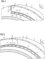
- Figure 7 shows an exemplary embodiment of the invention according to the previous figures, in a state in which the inner ring 5, the first outer clamping ring 6 and the second outer clamping ring 7, together with the fixation enhancement element 10, are placed onto the outer surface 2 of the wind turbine blade 1, but the inner ring, the first outer clamping ring 6 and the second outer clamping ring 7 are not yet locked by using the locking means 18.
- the inner ring 5 comprises a base 37 having mating surfaces 36, which couple with mating surfaces 35 of the first outer clamping ring 6 and the second outer clamping ring 7. Also, the first outer clamping ring 6 and the second outer clamping ring 7 have inner surfaces 34, which have a form corresponding to the wedge-shaped elements 23 of the fixation enhancement element 10.
- the locking means 18 here a screw, in the first through hole 16, the second through hole and the third through hole 14, which is threaded.
- the locking means 18 are also clamping means.
- the mating surfaces 36 of the base 37 of the fixation enhancement element 10 and the mating surface 35 of the first outer clamping ring 6 and the second outer clamping ring 7 also come in contact, so that the inner ring 5 is reliably held in a stable manner onto the outer surface 2 of the wind turbine blade 1.
Landscapes
- Engineering & Computer Science (AREA)
- Life Sciences & Earth Sciences (AREA)
- Sustainable Development (AREA)
- Sustainable Energy (AREA)
- Chemical & Material Sciences (AREA)
- Combustion & Propulsion (AREA)
- Mechanical Engineering (AREA)
- General Engineering & Computer Science (AREA)
- Wind Motors (AREA)
Priority Applications (5)
| Application Number | Priority Date | Filing Date | Title |
|---|---|---|---|
| EP23165980.6A EP4438892A1 (fr) | 2023-03-31 | 2023-03-31 | Ensemble de serrage |
| PCT/EP2024/056912 WO2024200041A1 (fr) | 2023-03-31 | 2024-03-15 | Ensemble de serrage |
| CN202480024024.2A CN121039389A (zh) | 2023-03-31 | 2024-03-15 | 夹持组件 |
| EP24711544.7A EP4665970A1 (fr) | 2023-03-31 | 2024-03-15 | Ensemble de serrage |
| TW113112011A TWI880694B (zh) | 2023-03-31 | 2024-03-29 | 夾緊組件 |
Applications Claiming Priority (1)
| Application Number | Priority Date | Filing Date | Title |
|---|---|---|---|
| EP23165980.6A EP4438892A1 (fr) | 2023-03-31 | 2023-03-31 | Ensemble de serrage |
Publications (1)
| Publication Number | Publication Date |
|---|---|
| EP4438892A1 true EP4438892A1 (fr) | 2024-10-02 |
Family
ID=85800440
Family Applications (2)
| Application Number | Title | Priority Date | Filing Date |
|---|---|---|---|
| EP23165980.6A Withdrawn EP4438892A1 (fr) | 2023-03-31 | 2023-03-31 | Ensemble de serrage |
| EP24711544.7A Pending EP4665970A1 (fr) | 2023-03-31 | 2024-03-15 | Ensemble de serrage |
Family Applications After (1)
| Application Number | Title | Priority Date | Filing Date |
|---|---|---|---|
| EP24711544.7A Pending EP4665970A1 (fr) | 2023-03-31 | 2024-03-15 | Ensemble de serrage |
Country Status (4)
| Country | Link |
|---|---|
| EP (2) | EP4438892A1 (fr) |
| CN (1) | CN121039389A (fr) |
| TW (1) | TWI880694B (fr) |
| WO (1) | WO2024200041A1 (fr) |
Citations (4)
| Publication number | Priority date | Publication date | Assignee | Title |
|---|---|---|---|---|
| US20150028608A1 (en) * | 2013-07-29 | 2015-01-29 | General Electric Company | Method and apparatus for handling a rotor blade |
| US20150233341A1 (en) * | 2014-02-20 | 2015-08-20 | General Electric Company | Methods and systems for removing and/or installing wind turbine rotor blades |
| US20190299393A1 (en) * | 2018-04-02 | 2019-10-03 | Tpi Composites, Inc. | Scissor lift system and plug-in mobility mechanism for wind turbine blade rotating device |
| CN112922794A (zh) * | 2019-12-05 | 2021-06-08 | 河北新天科创新能源技术有限公司 | 一种风力发电机的叶片更换装置及方法 |
Family Cites Families (2)
| Publication number | Priority date | Publication date | Assignee | Title |
|---|---|---|---|---|
| TWI672438B (zh) * | 2018-03-22 | 2019-09-21 | 行政院原子能委員會核能研究所 | 風力發電機葉片通用型夾具 |
| US12129826B2 (en) * | 2020-03-10 | 2024-10-29 | Vestas Wind Systems A/S | Method for handling a wind turbine blade |
-
2023
- 2023-03-31 EP EP23165980.6A patent/EP4438892A1/fr not_active Withdrawn
-
2024
- 2024-03-15 EP EP24711544.7A patent/EP4665970A1/fr active Pending
- 2024-03-15 WO PCT/EP2024/056912 patent/WO2024200041A1/fr not_active Ceased
- 2024-03-15 CN CN202480024024.2A patent/CN121039389A/zh active Pending
- 2024-03-29 TW TW113112011A patent/TWI880694B/zh active
Patent Citations (4)
| Publication number | Priority date | Publication date | Assignee | Title |
|---|---|---|---|---|
| US20150028608A1 (en) * | 2013-07-29 | 2015-01-29 | General Electric Company | Method and apparatus for handling a rotor blade |
| US20150233341A1 (en) * | 2014-02-20 | 2015-08-20 | General Electric Company | Methods and systems for removing and/or installing wind turbine rotor blades |
| US20190299393A1 (en) * | 2018-04-02 | 2019-10-03 | Tpi Composites, Inc. | Scissor lift system and plug-in mobility mechanism for wind turbine blade rotating device |
| CN112922794A (zh) * | 2019-12-05 | 2021-06-08 | 河北新天科创新能源技术有限公司 | 一种风力发电机的叶片更换装置及方法 |
Also Published As
| Publication number | Publication date |
|---|---|
| TWI880694B (zh) | 2025-04-11 |
| TW202449289A (zh) | 2024-12-16 |
| CN121039389A (zh) | 2025-11-28 |
| EP4665970A1 (fr) | 2025-12-24 |
| WO2024200041A1 (fr) | 2024-10-03 |
Similar Documents
| Publication | Publication Date | Title |
|---|---|---|
| EP0925455B1 (fr) | Dispositif de fixation | |
| TWI294492B (en) | Connector | |
| US9618051B2 (en) | Method and apparatus for mounting a machine element onto a shaft | |
| US9009937B2 (en) | Sleeve removal tool and sleeve removal method | |
| US20060285915A1 (en) | Apparatus for incrementally adjusting a modular tooling coupling | |
| US9221298B2 (en) | Hub clamp assembly | |
| US8782866B2 (en) | Angularly adjustable clamp assembly | |
| US20160375566A1 (en) | Tightening tool for coaxial connectors | |
| US6527233B2 (en) | Device for clamping a shaft | |
| US6223410B1 (en) | Pulling device | |
| US7559845B2 (en) | Nested disc pack coupling | |
| US20190226819A1 (en) | Universal nock system | |
| US7309187B2 (en) | Releasable keyless bushing assembly | |
| EP4665970A1 (fr) | Ensemble de serrage | |
| EP2395249A1 (fr) | Fil segmenté et agencement de connexion | |
| WO1990002272A2 (fr) | Dispositif de positionnement et de couplage d'arbres | |
| EP2708733B1 (fr) | Système de guidage pour guider une racine d'une pale de rotor pendant l'installation et procédé de montage d'une pale de rotor sur un moyeu de rotor d'une éolienne | |
| CA2560807C (fr) | Pince d'ancrage a boulon unique | |
| GB2181511A (en) | Expansion bolt for bolted couplings | |
| US20160252119A1 (en) | Serrated shaft-engaging surface for shrink disc | |
| US12601581B2 (en) | Generator rotor centering device | |
| JP2000179563A (ja) | 軸継手の軸締結装置 | |
| US10364847B2 (en) | Mounting device | |
| US12196251B2 (en) | Bearing assembly | |
| US20220196077A1 (en) | Assembly for connecting an adapter shaft to a shaft in a force-fitting manner using a clamping ring |
Legal Events
| Date | Code | Title | Description |
|---|---|---|---|
| PUAI | Public reference made under article 153(3) epc to a published international application that has entered the european phase |
Free format text: ORIGINAL CODE: 0009012 |
|
| STAA | Information on the status of an ep patent application or granted ep patent |
Free format text: STATUS: THE APPLICATION HAS BEEN PUBLISHED |
|
| AK | Designated contracting states |
Kind code of ref document: A1 Designated state(s): AL AT BE BG CH CY CZ DE DK EE ES FI FR GB GR HR HU IE IS IT LI LT LU LV MC ME MK MT NL NO PL PT RO RS SE SI SK SM TR |
|
| STAA | Information on the status of an ep patent application or granted ep patent |
Free format text: STATUS: THE APPLICATION IS DEEMED TO BE WITHDRAWN |
|
| 18D | Application deemed to be withdrawn |
Effective date: 20250403 |