EP4439059A1 - Système ultrasonore à laser à canaux multiples - Google Patents
Système ultrasonore à laser à canaux multiples Download PDFInfo
- Publication number
- EP4439059A1 EP4439059A1 EP24154697.7A EP24154697A EP4439059A1 EP 4439059 A1 EP4439059 A1 EP 4439059A1 EP 24154697 A EP24154697 A EP 24154697A EP 4439059 A1 EP4439059 A1 EP 4439059A1
- Authority
- EP
- European Patent Office
- Prior art keywords
- laser light
- laser
- detection
- generation
- ultrasonic
- Prior art date
- Legal status (The legal status is an assumption and is not a legal conclusion. Google has not performed a legal analysis and makes no representation as to the accuracy of the status listed.)
- Granted
Links
Images



Classifications
-
- G—PHYSICS
- G01—MEASURING; TESTING
- G01N—INVESTIGATING OR ANALYSING MATERIALS BY DETERMINING THEIR CHEMICAL OR PHYSICAL PROPERTIES
- G01N21/00—Investigating or analysing materials by the use of optical means, i.e. using sub-millimetre waves, infrared, visible or ultraviolet light
- G01N21/17—Systems in which incident light is modified in accordance with the properties of the material investigated
- G01N21/1702—Systems in which incident light is modified in accordance with the properties of the material investigated with opto-acoustic detection, e.g. for gases or analysing solids
-
- G—PHYSICS
- G01—MEASURING; TESTING
- G01N—INVESTIGATING OR ANALYSING MATERIALS BY DETERMINING THEIR CHEMICAL OR PHYSICAL PROPERTIES
- G01N29/00—Investigating or analysing materials by the use of ultrasonic, sonic or infrasonic waves; Visualisation of the interior of objects by transmitting ultrasonic or sonic waves through the object
- G01N29/04—Analysing solids
- G01N29/048—Marking the faulty objects
-
- G—PHYSICS
- G01—MEASURING; TESTING
- G01N—INVESTIGATING OR ANALYSING MATERIALS BY DETERMINING THEIR CHEMICAL OR PHYSICAL PROPERTIES
- G01N29/00—Investigating or analysing materials by the use of ultrasonic, sonic or infrasonic waves; Visualisation of the interior of objects by transmitting ultrasonic or sonic waves through the object
- G01N29/22—Details, e.g. general constructional or apparatus details
- G01N29/24—Probes
- G01N29/2418—Probes using optoacoustic interaction with the material, e.g. laser radiation, photoacoustics
-
- G—PHYSICS
- G01—MEASURING; TESTING
- G01N—INVESTIGATING OR ANALYSING MATERIALS BY DETERMINING THEIR CHEMICAL OR PHYSICAL PROPERTIES
- G01N29/00—Investigating or analysing materials by the use of ultrasonic, sonic or infrasonic waves; Visualisation of the interior of objects by transmitting ultrasonic or sonic waves through the object
- G01N29/22—Details, e.g. general constructional or apparatus details
- G01N29/26—Arrangements for orientation or scanning by relative movement of the head and the sensor
- G01N29/265—Arrangements for orientation or scanning by relative movement of the head and the sensor by moving the sensor relative to a stationary material
-
- G—PHYSICS
- G01—MEASURING; TESTING
- G01N—INVESTIGATING OR ANALYSING MATERIALS BY DETERMINING THEIR CHEMICAL OR PHYSICAL PROPERTIES
- G01N21/00—Investigating or analysing materials by the use of optical means, i.e. using sub-millimetre waves, infrared, visible or ultraviolet light
- G01N21/17—Systems in which incident light is modified in accordance with the properties of the material investigated
- G01N21/1702—Systems in which incident light is modified in accordance with the properties of the material investigated with opto-acoustic detection, e.g. for gases or analysing solids
- G01N2021/1706—Systems in which incident light is modified in accordance with the properties of the material investigated with opto-acoustic detection, e.g. for gases or analysing solids in solids
-
- G—PHYSICS
- G01—MEASURING; TESTING
- G01N—INVESTIGATING OR ANALYSING MATERIALS BY DETERMINING THEIR CHEMICAL OR PHYSICAL PROPERTIES
- G01N2201/00—Features of devices classified in G01N21/00
- G01N2201/06—Illumination; Optics
- G01N2201/061—Sources
- G01N2201/06113—Coherent sources; lasers
-
- G—PHYSICS
- G01—MEASURING; TESTING
- G01N—INVESTIGATING OR ANALYSING MATERIALS BY DETERMINING THEIR CHEMICAL OR PHYSICAL PROPERTIES
- G01N2201/00—Features of devices classified in G01N21/00
- G01N2201/06—Illumination; Optics
- G01N2201/063—Illuminating optical parts
- G01N2201/0636—Reflectors
-
- G—PHYSICS
- G01—MEASURING; TESTING
- G01N—INVESTIGATING OR ANALYSING MATERIALS BY DETERMINING THEIR CHEMICAL OR PHYSICAL PROPERTIES
- G01N2201/00—Features of devices classified in G01N21/00
- G01N2201/08—Optical fibres; light guides
-
- G—PHYSICS
- G01—MEASURING; TESTING
- G01N—INVESTIGATING OR ANALYSING MATERIALS BY DETERMINING THEIR CHEMICAL OR PHYSICAL PROPERTIES
- G01N2201/00—Features of devices classified in G01N21/00
- G01N2201/10—Scanning
-
- G—PHYSICS
- G01—MEASURING; TESTING
- G01N—INVESTIGATING OR ANALYSING MATERIALS BY DETERMINING THEIR CHEMICAL OR PHYSICAL PROPERTIES
- G01N2291/00—Indexing codes associated with group G01N29/00
- G01N2291/02—Indexing codes associated with the analysed material
- G01N2291/023—Solids
- G01N2291/0231—Composite or layered materials
-
- G—PHYSICS
- G01—MEASURING; TESTING
- G01N—INVESTIGATING OR ANALYSING MATERIALS BY DETERMINING THEIR CHEMICAL OR PHYSICAL PROPERTIES
- G01N2291/00—Indexing codes associated with group G01N29/00
- G01N2291/10—Number of transducers
- G01N2291/106—Number of transducers one or more transducer arrays
-
- G—PHYSICS
- G01—MEASURING; TESTING
- G01N—INVESTIGATING OR ANALYSING MATERIALS BY DETERMINING THEIR CHEMICAL OR PHYSICAL PROPERTIES
- G01N2291/00—Indexing codes associated with group G01N29/00
- G01N2291/26—Scanned objects
- G01N2291/269—Various geometry objects
- G01N2291/2694—Wings or other aircraft parts
Definitions
- the present disclosure relates to a laser ultrasound inspection system. More particularly, the present disclosure relates to a multiple channel laser ultrasonic system using a single detection laser and a single generation laser for inspecting internal structures of a component.
- Nondestructive inspection is commonly used to evaluate the properties of a part without altering the ability of the part to be used for its desired function. Examples of nondestructive inspection include ultrasound testing, eddy current testing, x-ray testing, and visual inspections.
- Ultrasound testing is often used to perform inspections on aircraft parts that are formed of composite materials. Ultrasound testing involves transmitting acoustic waves (e.g., sound waves) through a test object and detecting a response to the acoustic waves. The response is analyzed to determine whether inconsistencies or defects are present in the test object.
- acoustic waves e.g., sound waves
- Ultrasound testing is commonly performed using a transducer that is configured to send acoustic waves into the test object and detect the response to the acoustic waves.
- the transducer is coupled to a surface of the test object by placing the transducer in physical contact with the test object.
- a coupling medium such as water, oil, a water-based gel, or some other liquid, is used to reduce the acoustic impedance between the transducer and the test object.
- a coupling medium such as water, oil, a water-based gel, or some other liquid, is used to reduce the acoustic impedance between the transducer and the test object.
- coupling the transducer to the surface of the test object may be difficult and complex.
- test object when the test object has a non-constant geometry, a non-planar surface, or other non-planar features, it may be difficult and complex to couple the transducer to the test object in a manner that ensures that sound enters the test object in a desired direction, such as perpendicular to the surface.
- Laser ultrasound testing is an example of non-destructive inspection that allows for inspection of the test object without requiring physical contact with the test object.
- laser ultrasound testing uses a laser beam to generate ultrasonic waves in the test object and another separate laser beam to detect a response to the ultrasonic waves to generate data about the test object.
- laser ultrasound testing systems are generally less sensitive to the orientation relative to the test object.
- it can take a significant amount of time to perform testing of composite materials used in certain structures, such as aircraft, with laser ultrasound testing systems.
- the laser in laser ultrasound testing systems generally limit the rate of data acquisition, which tends to make such systems too expensive, slow, and bulky to be suitable for manufacturing inspection systems.
- the system includes a laser generator, a laser detector, a scanning apparatus, and a controller.
- the laser generator is configured to emit generation laser light.
- the laser detector is configured to emit detection laser light.
- the scanning apparatus is configured to: receive the generation laser light and the detection laser light; direct the generation laser light and the detection laser light onto a surface of a structure via a plurality of laser ultrasonic channels; and collect reflections of the detection laser light from the surface of the structure via the plurality of laser ultrasonic channels.
- the controller is coupled to the laser generator, the laser detector, and the scanning apparatus. The controller is configured to characterize an internal feature of the structure based on the reflections.
- the method includes generating, via a first plurality of beam splitters, a plurality of generation laser light beams from an emitted generation laser light.
- the method also includes generating, via a second plurality of beam splitters, a plurality of detection laser light beams from an emitted detection laser light.
- the method also includes, for each of a plurality of laser ultrasonic channels, (i) directing a respective one of the plurality of generation laser light beams and a respective one of the plurality of detection laser light beams to a surface of a structure via the laser ultrasonic channel and (ii) collecting one or more reflections of the respective one of the plurality of detection laser light beams via the laser ultrasonic channel.
- the method further includes characterizing an internal feature of the structure based on the reflections.
- the laser ultrasonic system includes a scanning head and a robotic arm coupled to the scanning head.
- the scanning head includes a laser generator configured to emit generation laser light, and a laser detector configured to emit detection laser light.
- the scanning head is configured to receive the generation laser light and the detection laser light.
- the scanning head is also configured to direct the generation laser light and the detection laser light onto a surface of a structure via a plurality of laser ultrasonic channels.
- the scanning head is further configured to collect reflections of the detection laser light from the surface of the structure via the plurality of laser ultrasonic channels.
- the present disclosure provides for ultrasound testing of various components using a laser ultrasonic (LUT) system, which includes multiple data acquisition channels, a single generation laser, and a single detection laser.
- LUT laser ultrasonic
- the LUT system is used for ultrasonic inspection of polymer-matrix composites during aircraft manufacturing.
- the LUT system described herein can significantly increase ultrasonic inspection speeds when scanning composite materials, increase signal quality, and maintain the cost of inspection low, relative to conventional laser ultrasonic inspection systems.
- the LUT system includes an inspection or scanning head that shares the generation and detection laser beams from a single generation laser and a single detection laser, respectively, among multiple channels.
- a single generation laser and a single detection laser enables a laser ultrasonic system to use higher quality, higher power lasers, while minimizing the capital cost per channel because the cost per unit of power is generally lower for industrial lasers relative to smaller custom-type lasers or diode lasers.
- the total system cost for such an approach becomes similar to an approach that uses smaller lasers.
- more power may be available with a LUT system with multiple channels, because industrial lasers have a lower cost per unit of laser power, relative to smaller lasers. More power, in turn, may translate into a higher quality signal (e.g., a larger signal-to-noise ratio (SNR)).
- SNR signal-to-noise ratio
- the higher quality signals may translate into a better incidence angle tolerance and longer depth of fields, which in turn can result in a larger range of possible applications and higher manufacturing throughput.
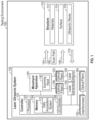
- FIG. 1 is a block diagram illustrating an example testing environment 100, according to certain embodiments.
- the testing environment 100 includes a LUT system 102, which is used to test a structure 110.
- the structure 110 is generally representative of any article or object that is to be tested using the LUT system 102.
- the structure 110 may include materials or components of an aircraft, vehicle, ship, or other structures.
- the LUT system 102 includes a controller 130, a movement apparatus 140, a (single) laser generator 154, a (single) laser detector 156, one or more optical fibers 158, one or more optical fibers 152, one or more interferometers 150, and one or more optical fibers 160.
- the controller 130 is generally configured to control one or more components of the LUT system 102, including, for example, the movement apparatus 140, laser generator 154, laser detector 156, and interferometer(s) 150.
- the controller 130 includes a processor 132, a memory 134, and one or more input/output (I/O) devices 138.
- the processor 132 is any electronic circuitry, including, but not limited to one or a combination of microprocessors, microcontrollers, application specific integrated circuits (ASIC), application specific instruction set processor (ASIP), and/or state machines, that communicatively couples to memory 134 and controls the operation of the LUT system 102.
- the processor 132 may be 8-bit, 16-bit, 32-bit, 64-bit or of any other suitable architecture.
- the processor 132 may include an arithmetic logic unit (ALU) for performing arithmetic and logic operations, processor registers that supply operands to the ALU and store the results of ALU operations, and a control unit that fetches instructions from memory and executes them by directing the coordinated operations of the ALU, registers and other components.
- the processor 132 may include other hardware that operates software to control and process information.
- the processor 132 executes software stored on the memory 134 to perform any of the functions described herein.
- the processor 132 controls the operation and administration of the controller 130 by processing information (e.g., information received from the processor 132, memory 134, and/or I/O devices 138).
- the processor 132 is not limited to a single processing device and may encompass multiple processing devices.
- the memory 134 may store, either permanently or temporarily, data, operational software, or other information for the processor 132.
- the memory 134 may include any one or a combination of volatile or non-volatile local or remote devices suitable for storing information.
- the memory 134 may include random access memory (RAM), read only memory (ROM), magnetic storage devices, optical storage devices, or any other suitable information storage device or a combination of these devices.
- the software represents any suitable set of instructions, logic, or code embodied in a computer-readable storage medium.
- the software may be embodied in the memory 134, a disk, a CD, or a flash drive.
- the software may include an application executable by the processor 132 to perform one or more of the functions described herein.
- the memory 134 includes a data acquisition system 172, which is described in greater detail herein.
- the I/O devices 138 may include, but are not limited to, one or more of a keypad, a keyboard, a touchsensitive display screen, a liquid crystal display (LCD) screen, a microphone, a speaker, a communication port, or any combination thereof.
- the laser generator 154 is configured to emit generation laser light 144.
- the generation laser light 144 emitted from the laser generator 154 is in the form of a laser pulse.
- the laser detector 156 is configured to generate detection laser light 148.
- the laser detector 156 generates the detection laser light 148 to illuminate the surface 114 of the structure 110 where surface displacements associated with ultrasonic waves are expected to occur.
- the laser detector 156 can be a continuous laser or long pulsed laser. Note, however, that the laser detector 154 can emit detection laser light 148 with any duration, frequency, and power.
- one or more parameters of the generation laser light 144 and/or the detection laser light 148 may be based on the materials 112 used to form the structure 110.
- the movement apparatus 140 includes a scanning head 142, which is generally configured to position and focus the generation laser light 144 (emitted from the laser generator 154) and the detection laser light 148 (emitted from the laser detector 156) onto the structure 110.
- the scanning head 142 may receive the generation laser light 144 via one or more optical fibers 158, optics, or a combination thereof.
- the scanning head 142 may receive the detection laser light 148 via one or more optical fibers 152, optics, or a combination thereof.
- the scanning head 142 may include an optical scanner, a mirror scanner, or another type of scanner. In one embodiment, scanning head 142 may not include a scanner, in which case scanning may be accomplished by movement apparatus 140 moving scanning head 142.
- one or more components of the LUT system 102 are mounted, or partially mounted, in the scanning head 142.
- the scanning head 142 may include the laser generator 154 and the laser detector 156.
- at least one of the laser generator 154 or the laser detector 156 can be partially mounted in the scanning head 142.
- the laser generator 154 may receive the generation laser light 144 through optics, optical fiber(s) 158, or a combination thereof, and the laser detector 156 may receive the detection laser light 148 through optics, optical fiber(s) 152, or a combination thereof.
- the movement apparatus 140 can move the scanning head 142 in relation to the structure 110.
- the controller 130 can control the movement apparatus 140 so that the generation laser light 144 and detection laser light 148 moves over the structure 110 along a scan path 146.
- the movement apparatus 140 is a robot, a robotic arm, or a gantry.
- the scanning head 142 can move the generation laser light 144 and/or the detection laser light 148 at the surface 114 of the structure 110 to inspect an area of the structure 110 for a given position of the scanning head 142.
- the scanning may be achieved by movements of the movement apparatus 140.
- the generation laser light 144 is absorbed at the surface 114 of the structure 110.
- the absorption of the generation laser light 144 creates a sudden localized thermal expansion that sends ultrasonic waves 118 into the structure 110.
- the ultrasonic waves 118 may be sent in a direction that is normal relative to the surface 114 of the structure 110, notwithstanding the incidence angle of the generation laser light 144.
- the detection laser light 148 illuminates the surface 114 of the structure 110 where surface displacements associated with the ultrasonic waves 118 are expected to occur.
- the detection laser light 148 is reflected off the surface 114 of the structure 110 (shown as reflected detection laser light 170).
- the reflected detection laser light 170 may be collected by a set of collection optics (not shown) and may be received by one or more interferometers 150 via one or more optical fibers 160.
- the interferometer(s) 150 may demodulate the reflected detection laser light 170 to extract an ultrasonic signal.
- the interferometer(s) 150 are representative of different types of interferometers, including, for example, confocal Fabry-Perot interferometers, photorefractive interferometers, and fiber-based Sagnac interferometers.
- the interferometer(s) 150 may be integral or external to the scanning head 142.
- the controller 130 via the data acquisition system 172, may analyze the extracted ultrasonic signal to determine whether a defect is present in the structure 110.
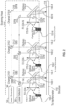
- FIG 2 illustrates an example scanning head 242 of a LUT system 102, according to one embodiment.
- the scanning head 242 is an example implementation of the scanning head 142 illustrated in Figure 1 .
- the laser generator 154 and the laser detector 156 are located within the scanning head 242.
- at least one of the laser generator 154 or the laser detector 156 is partially located in the scanning head 242.
- the laser generator 154 and the laser detector 156 are optically coupled using moving mirrors, articulated mirrors, or a combination of moving and articulated mirrors.
- the scanning head 242 includes multiple channels 210 1-N.
- the generation laser light 144 emitted from the laser generator 154 is directed towards a (first) LUT channel 210-1.
- a (first) generation beam splitter (GBS) 216-1 reflects a fraction of power of the original generation laser light 144 towards the surface 114 of the structure 110 through a (first) Dichroic 220-1 as generation laser light 144-1, and the rest of the power of the generation laser light 144 is directed towards a (second) LUT channel 210-2.
- a (second) GBS 216-2 reflects another fraction of the remaining power of the generation laser light 144 towards the surface 114 of the structure 110 through a (second) Dichroic 220-2 as generation laser light 144-2, and the rest of the power of the power of the generation laser light 144 is directed towards a (third) LUT channel (not shown). This pattern is repeated until the remaining power of the generation laser light 144 reaches the last (N th ) LUT channel 210-N, where the generation laser light is completely reflected by a generation final mirror (GFM) 218 towards the surface 114 of the structure through a (N th ) Dichroic 220-N as generation laser light 144-N.
- GBM generation final mirror
- the detection laser light 148 emitted from the laser detector 156 is directed towards the (first) LUT channel 210-1.
- a (first) detection beam splitter (DBS) 212-1 reflects a fraction of power of the original detection laser light 148 towards a (first) detection turning mirror (DTM) 222-1, and the rest of the power of the detection laser light 148 is directed towards a (second) LUT channel 210-2.
- the DTM 222-1 reflects the fraction of power of the original detection laser light 148 towards Dichroic 220-1, which, in turn, reflects the fraction of power of the original detection laser light 148 towards the surface 114 of the structure 110 as detection laser light 148-1.
- a (second) DBS 212-2 reflects another fraction of power of the remaining detection laser light 148 towards a (second) DTM 222-2, and the rest of the power of the detection laser light 148 is directed towards a (third) LUT channel (not shown).
- the DTM 222-2 reflects the other fraction of power of the remaining detection laser light 148 towards Dichroic 220-2, which, in turn, reflects the other fraction of power of the remaining detection laser light 148 towards the surface 114 of the structure 110 as detection laser light 148-2.
- This pattern is repeated until the remaining power of the detection laser light 148 reaches the last (N th ) LUT channel, where the detection laser light 148 is completely reflected by a detection final mirror (DFM) 214 towards an (N th ) DTM 222-N.
- the DTM 222-N then reflects the remaining power of the detection laser light 148 towards Dichroic 220-N, which, in turn, reflects the remaining power of the detection laser light 148 towards the surface 114 of the structure 110 as detection
- the detection laser light 148 1-N is scattered or reflected by the surface 114 as reflected detection laser light 170 1-N, respectively.
- the reflected detection laser light 170 1-N is reflected by the Dichroic 220 1-N towards focusing optics (FO) 224 1-N, respectively.
- the FO 224 1-N focus the reflected detection laser light 170 1-N into optical fibers 160 1-N, respectively.
- the optical fibers 160 1-N transmit the reflected detection laser light 170 1-N to interferometers 150 1-N, respectively.
- the interferometers 150 may be located within the scanning head 242, within the movement apparatus 140, or elsewhere within the testing environment 100.
- the generation laser light 144 and detection laser light 148 of all the LUT channels 210 can be made collinear or non-collinear.
- the generation laser light 144 and detection laser light 148 may form a pattern of inspection spots at the surface 114 of the structure 110, such that when a movement apparatus 140 moves the scanning head 142, the inspection rate of the structure 110 is increased by a factor equal to the number of LUT channels 210 in the scanning head 142, relative to a scanning head containing a single LUT channel.
- the DBSs 212 and GBSs 216 have different characteristics so that the power of the generation laser light 144 and power of the detection laser light 148 are approximately the same for all the LUT channels 210.
- the generation laser light 144 and detection laser light 148 can be varied in any suitable manner in order to create a target number of inspection spots at one or more target locations of the structure 110.
- Figure 3 illustrates an example scanning head 342 of a LUT system 102, according to one embodiment.
- the scanning head 342 is an example implementation of the scanning head 142 illustrated in Figure 1 .
- the scanning head 342 does not include the laser generator 154 and the laser detector 156. That is, the generation laser light 144 and the detection laser light 148 are not generated within the scanning head 342.
- the generation laser light 144 emitted from the laser generator 154 and the detection laser light 148 emitted from the laser detector 156 are brought to the scanning head 342 by optical fibers 158 and 152, respectively.
- the generation laser light 144 and detection laser light 148 may follow a pattern similar to that depicted in Figure 2 .
- Figure 3 depicts both generation laser light 144 and detection laser light 148 being brought to the scanning head via respective optical fibers 158 and 152, in certain embodiments, at least one of the generation laser light 144 or the detection laser light 148 may be brought to the scanning head 342 by a respective optical fiber.
- FIG 4 illustrates an example scanning head 442 of a LUT system 102, according to one embodiment.
- the scanning head 442 is an example implementation of the scanning head 142 illustrated in Figure 1 .
- the scanning head 442 does not include the laser generator 154 and the laser detector 156. That is, the generation laser light 144 and the detection laser light 148 are not generated within the scanning head 342.
- at least one of the generation laser light 144 emitted from the laser generator 154 or the detection laser light 148 emitted from the laser detector 156 may be split and injected into a number of optical fibers equal to the number of LUT channels 210 in the scanning head 442.
- the generation laser light 144 from the single laser generator 154 is distributed to each of the multiple channels 210 1-N via respective optical fibers 158 1-N.
- the detection laser light 148 from the single laser detector 165 is distributed to each of the multiple channels 210 1-N via respective optical fibers 152 1-N.
- each channel 210 is optically uncoupled from the other channels 210.
- a bundle of optical fibers may inject the generation laser light 144 or the detection laser light 148, or both, in a predefined pattern onto a single mirror and single Dichroic.
- the shape of scanning head 142, or the configuration of its optical components, or both may be adapted to inspect structures 110 that have surfaces that might be more complex than just flat.
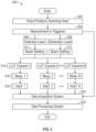
- FIG. 5 is a flowchart of a method 500 for performing a laser ultrasonic test to inspect a structure (e.g., structure 110), according to one embodiment.
- Method 500 enters with block 502, where a movement apparatus 140 (e.g., robot or gantry) positions the scanning head 142 with respect to the structure 110.
- the laser ultrasonic measurement (including data acquisition system 172) is triggered (block 504).
- the laser generator 154 and laser detector 156 emit respective generation laser light 144 and detection laser light 148.
- the beams of the generation laser light 144 and detection laser light 148 are split into a number of laser light beams and a number of detection laser light beams, respectively.
- Each of the number of laser light beams and the number of detection laser light beams may correspond to the number of LUT channels 210.
- each pair of generation laser light beam and detection laser light beam is directed into a respective LUT channel 210.
- each LUT channel 210 directs its generation laser light beam and detection laser light beam towards the surface 114 of the structure 110 and collects the detection laser light beams reflected by the surface 114 of the structure 110.
- each LUT channel 210 directs collected detection laser light beams to its corresponding interferometer 150.
- Each interferometer 150 extracts ultrasonic information from the collected light, and sends the ultrasonic information to a data acquisition system 172 (block 520).
- the digitized data of the data acquisition system 172 is sent to a data processing system that adds the data for the current inspection spots to the total inspection data for the current structure 110. If the inspection is not completed, then the method 500 goes to block 502 to position the movement apparatus 140 to the next inspection location.
- FIG 6 illustrates an example testing environment 600, according to one embodiment.
- the testing environment 600 is an example implementation of the testing environment 100 depicted in Figure 1 .
- the testing environment 600 includes a robot 640, which is used to move the scanning head 142 in relation to the structure 110.
- the robot 640 is one example implementation of the movement apparatus 140.
- the scanning head 142 is generally representative of any of the scanning heads described herein, including, for example scanning head 242, 342, and 442.
- aspects described herein may be embodied as a system, method or computer program product. Accordingly, aspects may take the form of an entirely hardware aspect, an entirely software aspect (including firmware, resident software, micro-code, etc.) or an aspect combining software and hardware aspects that may all generally be referred to herein as a "circuit,” “module” or “system.” Furthermore, aspects described herein may take the form of a computer program product embodied in one or more computer readable storage medium(s) having computer readable program code embodied thereon.
- Program code embodied on a computer readable storage medium may be transmitted using any appropriate medium, including but not limited to wireless, wireline, optical fiber cable, RF, etc., or any suitable combination of the foregoing.
- Computer program code for carrying out operations for aspects of the present disclosure may be written in any combination of one or more programming languages, including an object oriented programming language such as Java, Smalltalk, C++ or the like and conventional procedural programming languages, such as the "C" programming language or similar programming languages.
- the program code may execute entirely on the user's computer, partly on the user's computer, as a stand-alone software package, partly on the user's computer and partly on a remote computer or entirely on the remote computer or server.
- the remote computer may be connected to the user's computer through any type of network, including a local area network (LAN) or a wide area network (WAN), or the connection may be made to an external computer (for example, through the Internet using an Internet Service Provider).
- LAN local area network
- WAN wide area network
- Internet Service Provider for example, AT&T, MCI, Sprint, EarthLink, MSN, GTE, etc.
- These computer program instructions may also be stored in a computer readable medium that can direct a computer, other programmable data processing apparatus, or other device to function in a particular manner, such that the instructions stored in the computer readable medium produce an article of manufacture including instructions which implement the function/act specified in the block(s) of the flowchart illustrations and/or block diagrams.
- the computer program instructions may also be loaded onto a computer, other programmable data processing apparatus, or other device to cause a series of operational steps to be performed on the computer, other programmable apparatus or other device to produce a computer implemented process such that the instructions which execute on the computer, other programmable data processing apparatus, or other device provide processes for implementing the functions/acts specified in the block(s) of the flowchart illustrations and/or block diagrams.
- each block in the flowchart illustrations or block diagrams may represent a module, segment, or portion of code, which comprises one or more executable instructions for implementing the specified logical function(s).
- the functions noted in the block may occur out of the order noted in the Figures. For example, two blocks shown in succession may, in fact, be executed substantially concurrently, or the blocks may sometimes be executed in the reverse order or out of order, depending upon the functionality involved.
Landscapes
- Physics & Mathematics (AREA)
- General Physics & Mathematics (AREA)
- Pathology (AREA)
- Life Sciences & Earth Sciences (AREA)
- Chemical & Material Sciences (AREA)
- Analytical Chemistry (AREA)
- Biochemistry (AREA)
- Health & Medical Sciences (AREA)
- Immunology (AREA)
- General Health & Medical Sciences (AREA)
- Optics & Photonics (AREA)
- Acoustics & Sound (AREA)
- Investigating Or Analyzing Materials By The Use Of Ultrasonic Waves (AREA)
- Length Measuring Devices By Optical Means (AREA)
- Investigating Or Analysing Materials By Optical Means (AREA)
- Investigating Materials By The Use Of Optical Means Adapted For Particular Applications (AREA)
Applications Claiming Priority (1)
| Application Number | Priority Date | Filing Date | Title |
|---|---|---|---|
| US18/191,788 US12392710B2 (en) | 2023-03-28 | 2023-03-28 | Multiple channel laser ultrasonic system |
Publications (2)
| Publication Number | Publication Date |
|---|---|
| EP4439059A1 true EP4439059A1 (fr) | 2024-10-02 |
| EP4439059B1 EP4439059B1 (fr) | 2026-06-10 |
Family
ID=89772018
Family Applications (1)
| Application Number | Title | Priority Date | Filing Date |
|---|---|---|---|
| EP24154697.7A Active EP4439059B1 (fr) | 2023-03-28 | 2024-01-30 | Système ultrasonore à laser à canaux multiples |
Country Status (5)
| Country | Link |
|---|---|
| US (1) | US12392710B2 (fr) |
| EP (1) | EP4439059B1 (fr) |
| JP (1) | JP2024144114A (fr) |
| CN (1) | CN118731159A (fr) |
| CA (1) | CA3232124A1 (fr) |
Citations (3)
| Publication number | Priority date | Publication date | Assignee | Title |
|---|---|---|---|---|
| EP1007942A1 (fr) * | 1996-11-22 | 2000-06-14 | Perceptron, Inc. | Appareil de mesure d'un parametre physique et procede associe |
| US6128081A (en) * | 1996-11-22 | 2000-10-03 | Perceptron, Inc. | Method and system for measuring a physical parameter of at least one layer of a multilayer article without damaging the article and sensor head for use therein |
| EP2132560A1 (fr) * | 2007-02-21 | 2009-12-16 | Lockheed Martin Corporation | Robot articulé pour inspection au laser-ultrasonore |
Family Cites Families (2)
| Publication number | Priority date | Publication date | Assignee | Title |
|---|---|---|---|---|
| US11287507B2 (en) | 2018-04-30 | 2022-03-29 | The Boeing Company | System and method for testing a structure using laser ultrasound |
| JP2023509586A (ja) * | 2019-12-19 | 2023-03-09 | イルミソニックス インコーポレイテッド | 光音響リモートセンシング(pars)及び関連する使用方法 |
-
2023
- 2023-03-28 US US18/191,788 patent/US12392710B2/en active Active
-
2024
- 2024-01-25 JP JP2024009483A patent/JP2024144114A/ja active Pending
- 2024-01-30 EP EP24154697.7A patent/EP4439059B1/fr active Active
- 2024-02-20 CN CN202410188103.9A patent/CN118731159A/zh active Pending
- 2024-03-15 CA CA3232124A patent/CA3232124A1/en active Pending
Patent Citations (3)
| Publication number | Priority date | Publication date | Assignee | Title |
|---|---|---|---|---|
| EP1007942A1 (fr) * | 1996-11-22 | 2000-06-14 | Perceptron, Inc. | Appareil de mesure d'un parametre physique et procede associe |
| US6128081A (en) * | 1996-11-22 | 2000-10-03 | Perceptron, Inc. | Method and system for measuring a physical parameter of at least one layer of a multilayer article without damaging the article and sensor head for use therein |
| EP2132560A1 (fr) * | 2007-02-21 | 2009-12-16 | Lockheed Martin Corporation | Robot articulé pour inspection au laser-ultrasonore |
Also Published As
| Publication number | Publication date |
|---|---|
| CN118731159A (zh) | 2024-10-01 |
| EP4439059B1 (fr) | 2026-06-10 |
| CA3232124A1 (en) | 2025-06-25 |
| US20240328926A1 (en) | 2024-10-03 |
| US12392710B2 (en) | 2025-08-19 |
| JP2024144114A (ja) | 2024-10-11 |
Similar Documents
| Publication | Publication Date | Title |
|---|---|---|
| CN107024542B (zh) | 用于测试对象的机载超声测试系统 | |
| US10352911B2 (en) | Airborne ultrasound testing system for a test object | |
| JPS606860A (ja) | 非接触式超音波探傷方法およびその装置 | |
| JP4386709B2 (ja) | レーザ超音波による材料非破壊検査方法及び装置 | |
| Fischer et al. | Acoustic Process Control for Laser Material Processing: Optical microphone as a novel “ear” for industrial manufacturing | |
| KR20090122424A (ko) | 레이저 초음파 검사를 위한 다관절 로봇 | |
| US10197535B2 (en) | Apparatus and method for full-field pulse-echo laser ultrasonic propagation imaging | |
| CN111323480B (zh) | 一种手持式自动对焦激光超声无损检测系统 | |
| US11692810B2 (en) | Photoacoustic excitation sensing enhanced by cross-correlated unfocused speckle images | |
| US20130088724A1 (en) | Method and apparatus for the inspection of sandwich structures using laser-induced resonant frequencies | |
| CN118914363A (zh) | 一种金属增材制造件缺陷检测系统及方法 | |
| CN109799191B (zh) | 固体材料粗糙表面声扰动的光学非接触检测装置及方法 | |
| US12392710B2 (en) | Multiple channel laser ultrasonic system | |
| WO2011108855A2 (fr) | Appareil destiné à imager une propagation par ultrasons anormale | |
| KR101664470B1 (ko) | 빔 스플리터의 후면 반사를 이용한 다중 광경로 레이저 광학계 | |
| JP2003215111A (ja) | レーザ計測用プローブおよびレーザ計測装置 | |
| BR102024005606A2 (pt) | Sistema ultrassônico a laser de múltiplos canais | |
| JPH11271281A (ja) | レーザー超音波検査装置及びレーザー超音波検査方法 | |
| JP2503139Y2 (ja) | レ―ザ―超音波斜角探傷装置 | |
| US20240329005A1 (en) | Multi pump-probe encoding-decoding for opto-acoustic metrology | |
| CN110793918B (zh) | 基于空间自由分布光路的工业oct检测装置及方法 | |
| JPS63269054A (ja) | 超音波ビ−ム入射状況確認装置 | |
| RU95109005A (ru) | Способ бесконтактной ультразвуковой дефектоскопии и акустическое устройство дистанционной диагностики | |
| JP2026051598A (ja) | 超音波検査装置および超音波検査方法 | |
| JP2024062497A (ja) | 超音波検査装置および超音波検査方法 |
Legal Events
| Date | Code | Title | Description |
|---|---|---|---|
| PUAI | Public reference made under article 153(3) epc to a published international application that has entered the european phase |
Free format text: ORIGINAL CODE: 0009012 |
|
| STAA | Information on the status of an ep patent application or granted ep patent |
Free format text: STATUS: THE APPLICATION HAS BEEN PUBLISHED |
|
| AK | Designated contracting states |
Kind code of ref document: A1 Designated state(s): AL AT BE BG CH CY CZ DE DK EE ES FI FR GB GR HR HU IE IS IT LI LT LU LV MC ME MK MT NL NO PL PT RO RS SE SI SK SM TR |
|
| STAA | Information on the status of an ep patent application or granted ep patent |
Free format text: STATUS: REQUEST FOR EXAMINATION WAS MADE |
|
| 17P | Request for examination filed |
Effective date: 20250210 |
|
| STAA | Information on the status of an ep patent application or granted ep patent |
Free format text: STATUS: EXAMINATION IS IN PROGRESS |
|
| 17Q | First examination report despatched |
Effective date: 20250526 |
|
| REG | Reference to a national code |
Ref country code: DE Ref legal event code: R079 Free format text: PREVIOUS MAIN CLASS: G01N0029240000 Ipc: G01N0029265000 Ref country code: DE Ref legal event code: R079 Ref document number: 602024005314 Country of ref document: DE Free format text: PREVIOUS MAIN CLASS: G01N0029240000 Ipc: G01N0029265000 |
|
| GRAP | Despatch of communication of intention to grant a patent |
Free format text: ORIGINAL CODE: EPIDOSNIGR1 |
|
| STAA | Information on the status of an ep patent application or granted ep patent |
Free format text: STATUS: GRANT OF PATENT IS INTENDED |
|
| GRAJ | Information related to disapproval of communication of intention to grant by the applicant or resumption of examination proceedings by the epo deleted |
Free format text: ORIGINAL CODE: EPIDOSDIGR1 |
|
| STAA | Information on the status of an ep patent application or granted ep patent |
Free format text: STATUS: EXAMINATION IS IN PROGRESS |
|
| RIC1 | Information provided on ipc code assigned before grant |
Ipc: G01N 29/265 20060101AFI20260203BHEP Ipc: G01N 29/24 20060101ALI20260203BHEP |
|
| INTG | Intention to grant announced |
Effective date: 20260217 |
|
| INTC | Intention to grant announced (deleted) | ||
| GRAP | Despatch of communication of intention to grant a patent |
Free format text: ORIGINAL CODE: EPIDOSNIGR1 |
|
| STAA | Information on the status of an ep patent application or granted ep patent |
Free format text: STATUS: GRANT OF PATENT IS INTENDED |
|
| P01 | Opt-out of the competence of the unified patent court (upc) registered |
Free format text: CASE NUMBER: UPC_APP_0011296_4439059/2026 Effective date: 20260330 |
|
| GRAS | Grant fee paid |
Free format text: ORIGINAL CODE: EPIDOSNIGR3 |
|
| GRAA | (expected) grant |
Free format text: ORIGINAL CODE: 0009210 |
|
| STAA | Information on the status of an ep patent application or granted ep patent |
Free format text: STATUS: THE PATENT HAS BEEN GRANTED |
|
| INTG | Intention to grant announced |
Effective date: 20260504 |
|
| AK | Designated contracting states |
Kind code of ref document: B1 Designated state(s): AL AT BE BG CH CY CZ DE DK EE ES FI FR GB GR HR HU IE IS IT LI LT LU LV MC ME MK MT NL NO PL PT RO RS SE SI SK SM TR |
|
| REG | Reference to a national code |
Ref country code: CH Ref legal event code: F10 Free format text: ST27 STATUS EVENT CODE: U-0-0-F10-F00 (AS PROVIDED BY THE NATIONAL OFFICE) Effective date: 20260610 Ref country code: GB Ref legal event code: FG4D |
|
| REG | Reference to a national code |
Ref country code: IE Ref legal event code: FG4D |
|
| REG | Reference to a national code |
Ref country code: DE Ref legal event code: R096 Ref document number: 602024005314 Country of ref document: DE |