EP4439155A2 - Procédés d'exposition étagée spatiale et séquentielle pour la fabrication d'éléments diffractants d'un dispositif guide d'ondes ou d'un moteur optique - Google Patents
Procédés d'exposition étagée spatiale et séquentielle pour la fabrication d'éléments diffractants d'un dispositif guide d'ondes ou d'un moteur optique Download PDFInfo
- Publication number
- EP4439155A2 EP4439155A2 EP24186947.8A EP24186947A EP4439155A2 EP 4439155 A2 EP4439155 A2 EP 4439155A2 EP 24186947 A EP24186947 A EP 24186947A EP 4439155 A2 EP4439155 A2 EP 4439155A2
- Authority
- EP
- European Patent Office
- Prior art keywords
- diffractive element
- light
- photopolymer
- diffractive
- stepped
- Prior art date
- Legal status (The legal status is an assumption and is not a legal conclusion. Google has not performed a legal analysis and makes no representation as to the accuracy of the status listed.)
- Pending
Links
- 230000003287 optical effect Effects 0.000 title claims description 42
- 238000000034 method Methods 0.000 title claims description 25
- 238000004519 manufacturing process Methods 0.000 title claims description 5
- 230000001537 neural effect Effects 0.000 claims description 8
- 239000000178 monomer Substances 0.000 claims description 6
- 238000002834 transmittance Methods 0.000 claims description 6
- 239000003999 initiator Substances 0.000 claims description 4
- 229920000642 polymer Polymers 0.000 claims description 4
- 241001270131 Agaricus moelleri Species 0.000 claims description 2
- 239000011230 binding agent Substances 0.000 claims description 2
- 230000008569 process Effects 0.000 claims description 2
- 230000001131 transforming effect Effects 0.000 claims 1
- 238000010586 diagram Methods 0.000 description 10
- 230000015572 biosynthetic process Effects 0.000 description 8
- 230000003190 augmentative effect Effects 0.000 description 3
- 230000000644 propagated effect Effects 0.000 description 3
- 230000007423 decrease Effects 0.000 description 2
- 239000011521 glass Substances 0.000 description 2
- 239000000463 material Substances 0.000 description 2
- 230000004048 modification Effects 0.000 description 2
- 238000012986 modification Methods 0.000 description 2
- 210000001747 pupil Anatomy 0.000 description 2
- 230000008859 change Effects 0.000 description 1
- 239000003086 colorant Substances 0.000 description 1
- 230000007246 mechanism Effects 0.000 description 1
- 238000006552 photochemical reaction Methods 0.000 description 1
- 238000006116 polymerization reaction Methods 0.000 description 1
- 230000009467 reduction Effects 0.000 description 1
Images



Classifications
-
- G—PHYSICS
- G02—OPTICS
- G02B—OPTICAL ELEMENTS, SYSTEMS OR APPARATUS
- G02B27/00—Optical systems or apparatus not provided for by any of the groups G02B1/00 - G02B26/00, G02B30/00
- G02B27/01—Head-up displays
- G02B27/017—Head mounted
- G02B27/0172—Head mounted characterised by optical features
-
- G—PHYSICS
- G02—OPTICS
- G02B—OPTICAL ELEMENTS, SYSTEMS OR APPARATUS
- G02B6/00—Light guides; Structural details of arrangements comprising light guides and other optical elements, e.g. couplings
- G02B6/24—Coupling light guides
- G02B6/26—Optical coupling means
- G02B6/262—Optical details of coupling light into, or out of, or between fibre ends, e.g. special fibre end shapes or associated optical elements
-
- G—PHYSICS
- G02—OPTICS
- G02B—OPTICAL ELEMENTS, SYSTEMS OR APPARATUS
- G02B27/00—Optical systems or apparatus not provided for by any of the groups G02B1/00 - G02B26/00, G02B30/00
- G02B27/42—Diffraction optics, i.e. systems including a diffractive element being designed for providing a diffractive effect
- G02B27/4272—Diffraction optics, i.e. systems including a diffractive element being designed for providing a diffractive effect having plural diffractive elements positioned sequentially along the optical path
-
- G—PHYSICS
- G02—OPTICS
- G02B—OPTICAL ELEMENTS, SYSTEMS OR APPARATUS
- G02B27/00—Optical systems or apparatus not provided for by any of the groups G02B1/00 - G02B26/00, G02B30/00
- G02B27/01—Head-up displays
- G02B27/0101—Head-up displays characterised by optical features
-
- G—PHYSICS
- G02—OPTICS
- G02B—OPTICAL ELEMENTS, SYSTEMS OR APPARATUS
- G02B5/00—Optical elements other than lenses
- G02B5/18—Diffraction gratings
- G02B5/1847—Manufacturing methods
- G02B5/1857—Manufacturing methods using exposure or etching means, e.g. holography, photolithography, exposure to electron or ion beams
-
- G—PHYSICS
- G02—OPTICS
- G02B—OPTICAL ELEMENTS, SYSTEMS OR APPARATUS
- G02B6/00—Light guides; Structural details of arrangements comprising light guides and other optical elements, e.g. couplings
- G02B6/10—Light guides; Structural details of arrangements comprising light guides and other optical elements, e.g. couplings of the optical waveguide type
- G02B6/12—Light guides; Structural details of arrangements comprising light guides and other optical elements, e.g. couplings of the optical waveguide type of the integrated circuit kind
-
- G—PHYSICS
- G02—OPTICS
- G02B—OPTICAL ELEMENTS, SYSTEMS OR APPARATUS
- G02B6/00—Light guides; Structural details of arrangements comprising light guides and other optical elements, e.g. couplings
- G02B6/10—Light guides; Structural details of arrangements comprising light guides and other optical elements, e.g. couplings of the optical waveguide type
- G02B6/12—Light guides; Structural details of arrangements comprising light guides and other optical elements, e.g. couplings of the optical waveguide type of the integrated circuit kind
- G02B6/122—Basic optical elements, e.g. light-guiding paths
- G02B6/124—Geodesic lenses or integrated gratings
-
- G—PHYSICS
- G03—PHOTOGRAPHY; CINEMATOGRAPHY; ANALOGOUS TECHNIQUES USING WAVES OTHER THAN OPTICAL WAVES; ELECTROGRAPHY; HOLOGRAPHY
- G03B—APPARATUS OR ARRANGEMENTS FOR TAKING PHOTOGRAPHS OR FOR PROJECTING OR VIEWING THEM; APPARATUS OR ARRANGEMENTS EMPLOYING ANALOGOUS TECHNIQUES USING WAVES OTHER THAN OPTICAL WAVES; ACCESSORIES THEREFOR
- G03B21/00—Projectors or projection-type viewers; Accessories therefor
- G03B21/14—Details
-
- G—PHYSICS
- G03—PHOTOGRAPHY; CINEMATOGRAPHY; ANALOGOUS TECHNIQUES USING WAVES OTHER THAN OPTICAL WAVES; ELECTROGRAPHY; HOLOGRAPHY
- G03H—HOLOGRAPHIC PROCESSES OR APPARATUS
- G03H1/00—Holographic processes or apparatus using light, infrared or ultraviolet waves for obtaining holograms or for obtaining an image from them; Details peculiar thereto
- G03H1/02—Details of features involved during the holographic process; Replication of holograms without interference recording
- G03H1/024—Hologram nature or properties
- G03H1/0248—Volume holograms
-
- G—PHYSICS
- G02—OPTICS
- G02B—OPTICAL ELEMENTS, SYSTEMS OR APPARATUS
- G02B6/00—Light guides; Structural details of arrangements comprising light guides and other optical elements, e.g. couplings
- G02B6/10—Light guides; Structural details of arrangements comprising light guides and other optical elements, e.g. couplings of the optical waveguide type
- G02B6/12—Light guides; Structural details of arrangements comprising light guides and other optical elements, e.g. couplings of the optical waveguide type of the integrated circuit kind
- G02B2006/12083—Constructional arrangements
- G02B2006/12107—Grating
-
- G—PHYSICS
- G02—OPTICS
- G02B—OPTICAL ELEMENTS, SYSTEMS OR APPARATUS
- G02B27/00—Optical systems or apparatus not provided for by any of the groups G02B1/00 - G02B26/00, G02B30/00
- G02B27/0081—Optical systems or apparatus not provided for by any of the groups G02B1/00 - G02B26/00, G02B30/00 with means for altering, e.g. enlarging, the entrance or exit pupil
-
- G—PHYSICS
- G03—PHOTOGRAPHY; CINEMATOGRAPHY; ANALOGOUS TECHNIQUES USING WAVES OTHER THAN OPTICAL WAVES; ELECTROGRAPHY; HOLOGRAPHY
- G03H—HOLOGRAPHIC PROCESSES OR APPARATUS
- G03H1/00—Holographic processes or apparatus using light, infrared or ultraviolet waves for obtaining holograms or for obtaining an image from them; Details peculiar thereto
- G03H1/04—Processes or apparatus for producing holograms
- G03H1/0402—Recording geometries or arrangements
- G03H2001/0439—Recording geometries or arrangements for recording Holographic Optical Element [HOE]
Definitions
- the present disclosure relates to spatial and sequential stepped exposure methods for manufacturing diffracting elements of a waveguide device and an optical engine.
- Various types of computing, entertainment, and/or mobile devices can be implemented with a transparent or semi-transparent display through which a user of a device can view the surrounding environment.
- Such devices which can be referred to as see-through, mixed reality display device systems, or as augmented reality (AR) systems, enable a user to see through the transparent or semi-transparent display of a device to view the surrounding environment, and also see images of virtual objects (e.g., text, graphics, video, etc.) that are generated for display to appear as a part of, and/or overlaid upon, the surrounding environment.
- virtual objects e.g., text, graphics, video, etc.
- HMD head-mounted display
- These devices which can be implemented as head-mounted display (HMD) glasses or other wearable display devices, but are not limited thereto, often utilize optical waveguides to replicate an image to a location where a user of a device can view the image as a virtual image in an augmented reality environment.
- HMD head-mounted display
- An aspect of the disclosure is to provide a waveguide device and an optical engine that can efficiently solve the aforementioned problems.
- a waveguide device includes a first diffractive element, a second diffractive element, a third diffractive element, and a waveguide element.
- the first diffractive element is configured to diffract light of a wavelength to propagate with a diffraction angle.
- the second diffractive element is configured to diffract the light of the wavelength to propagate with the diffraction angle.
- the third diffractive element is configured to diffract the light of the wavelength to propagate with the diffraction angle.
- the waveguide element is configured to guide the light of the wavelength to propagate from the first diffractive element to the second diffractive element and the third diffractive element. Diffraction efficiencies of the second diffractive element and the third diffractive element are different.
- the first diffractive element is spaced apart from the second diffractive element and the third diffractive element.
- a distance between the first diffractive element and the second diffractive element is smaller than a distance between the first diffractive element and the third diffractive element.
- the diffraction efficiency of the second diffractive element is smaller than the diffraction efficiency of the third diffractive element.
- the waveguide element has opposite sides.
- the first diffractive element is disposed at one of the opposite sides.
- the second diffractive element and the third diffractive element are disposed on another of the opposite sides.
- the first diffractive element, the second diffractive element, and the third diffractive element are reflective diffractive elements.
- the waveguide device further includes a fourth diffractive element.
- the fourth diffractive element is configured to diffract the light of the wavelength to propagate with the diffraction angle.
- the second diffractive element, the third diffractive element, and the fourth diffractive element are disposed on a surface of the waveguide element and sequentially arranged along a direction.
- the diffraction efficiency of the third diffractive element is greater than the diffraction efficiency of the second diffractive element and smaller than a diffraction efficiency of the fourth diffractive element.
- the third diffractive element is seamlessly connected to the second diffractive element and the fourth diffractive element.
- an optical engine includes a projector, a first diffractive element, a second diffractive element, a third diffractive element, and a waveguide element.
- the first diffractive element is configured to diffract the light of the wavelength to propagate with a diffraction angle.
- the second diffractive element is configured to diffract the light of the wavelength to propagate with the diffraction angle.
- the third diffractive element is configured to diffract the light of the wavelength to propagate with the diffraction angle.
- the waveguide element is configured to guide the light of the wavelength to propagate from the first diffractive element to the second diffractive element and the third diffractive element, wherein diffraction efficiencies of the second diffractive element and the third diffractive element are different.
- the first diffractive element is spaced apart from the second diffractive element and the third diffractive element.
- a distance between the first diffractive element and the second diffractive element is smaller than a distance between the first diffractive element and the third diffractive element.
- the diffraction efficiency of the second diffractive element is smaller than the diffraction efficiency of the third diffractive element.
- the light diffracted by the first diffractive element sequentially reaches the second diffractive element and the third diffractive element through the waveguide element.
- the diffraction efficiency of the second diffractive element is smaller than the diffraction efficiency of the third diffractive element.
- the waveguide element has opposite sides.
- the first diffractive element is disposed at one of the opposite sides.
- the second diffractive element and the third diffractive element are disposed on another of the opposite sides.
- the first diffractive element, the second diffractive element, and the third diffractive element are reflective diffractive elements.
- the optical engine further includes a fourth diffractive element.
- the fourth diffractive element is configured to diffract the light of the wavelength to propagate with the diffraction angle.
- the second diffractive element, the third diffractive element, and the fourth diffractive element are disposed on a surface of the waveguide element and sequentially arranged along a direction.
- the diffraction efficiency of the third diffractive element is greater than the diffraction efficiency of the second diffractive element and smaller than a diffraction efficiency of the fourth diffractive element.
- the third diffractive element is seamlessly connected to the second diffractive element and the fourth diffractive element.
- the light diffracted by the first diffractive element sequentially reaches the second diffractive element, the third diffractive element, and the fourth diffractive element through the waveguide element.
- the light projected by the projector reaches the first diffractive element through the waveguide element.
- the light reaching the first diffractive element is diffracted by the first diffractive element to sequentially reach the second diffractive element and the third diffractive element.
- the diffraction efficiencies of the second diffractive element and the third diffractive element increase as the energy of the totally reflected light decreases.
- the second diffractive element and the third diffractive element having different diffraction efficiencies can provide a wider eyebox range, and this range can provide a more uniform light intensity. It allows users to see uniformly bright and dark image content when laterally moving their eyes relative to the waveguide device and the optical engine.
- Fig. 1 is a schematic diagram of an optical engine 100 according to some embodiments of the present disclosure.
- the optical engine 100 may be used in an augmented reality device (not shown) which can be implemented as head-mounted display (HMD) glasses or other wearable display devices, but is not limited thereto.
- the optical engine 100 includes a projector 110 and a waveguide device 120.
- the waveguide device 120 includes a first diffractive element 121, a second diffractive element 122, a third diffractive element 123, a fourth diffractive element 124, and a waveguide element 125.
- the projector 110 is configured to project light of a wavelength.
- the first diffractive element 121 is configured to diffract the light of the wavelength to propagate with a diffraction angle.
- the second diffractive element 122 is configured to diffract the light of the wavelength to propagate with the diffraction angle.
- the third diffractive element 123 configured to diffract the light of the wavelength to propagate with the diffraction angle.
- the fourth diffractive element 124 is configured to diffract the light of the wavelength to propagate with the diffraction angle.
- the first diffractive element 121, the second diffractive element 122, the third diffractive element 123, and the fourth diffractive element 124 may have holographic gratings having an identical fringe pitch.
- the projector 110 is configured to project red light R, green light G, and blue light B (referring to Fig. 5 ), but the disclosure is not limited in this regard.
- the wavelength band of the red light R projected by the projector 110 is from about 622 nm to about 642 nm, but the disclosure is not limited in this regard.
- the wavelength band of the green light G projected by the projector 110 is from about 522 nm to about 542 nm, but the disclosure is not limited in this regard.
- the wavelength band of the blue light B projected by the projector 110 is from about 455 nm to about 475 nm, but the disclosure is not limited in this regard.
- the projector 110 adopts light-emitting diodes to project the red light R, the green light G, and the blue light B.
- the projector 110 may adopt laser diodes to project the red light R, the green light G, and the blue light B with smaller wavelength band.
- the holographic gratings of the first diffractive element 121, the second diffractive element 122, the third diffractive element 123, and the fourth diffractive element 124 are configured to diffract the red light R projected by the projector 110 to propagate with a first range of diffraction angle.
- the holographic gratings are configured to diffract light of which the wavelength is 632 nm (which is within the wavelength band of the red light R) to propagate with a first diffraction angle.
- the holographic gratings are configured to diffract the green light G projected by the projector 110 to propagate with a second range of diffraction angle.
- the holographic gratings are configured to diffract light of which the wavelength is 532 nm (which is within the wavelength band of the green light G) to propagate with a second diffraction angle.
- the third holographic gratings are configured to diffract the green light B projected by the projector 110 to propagate with a third range of diffraction angle.
- the holographic gratings are configured to diffract light of which the wavelength is 465 nm (which is within the wavelength band of the blue light B) to propagate with a first diffraction angle.
- the holographic gratings of the first diffractive element 121, the second diffractive element 122, the third diffractive element 123, and the fourth diffractive element 124 are volume holographic gratings. It is notable that light diffracted by a volume holographic grating can propagate with a specific diffraction angle based on the Bragg's law.
- the waveguide element 125 is configured to guide the light of the wavelength to propagate from the first diffractive element 121 to the second diffractive element 122, the third diffractive element 123, and the fourth diffractive element 124 based on the principle of total reflection.
- the light projected by the projector 110 can be inputted to the first diffractive element 121 and outputted from the second diffractive element 122, the third diffractive element 123, and the fourth diffractive element 124.
- the first diffractive element 121 serves as a light guiding element of light-input
- the second diffractive element 122, the third diffractive element 123, and the fourth diffractive element 124 serve as light guiding elements of light-output.
- diffraction efficiencies of the second diffractive element 122, the third diffractive element 123, and the fourth diffractive element 124 are different.
- the first diffractive element 121 is spaced apart from second diffractive element 122, the third diffractive element 123, and the fourth diffractive element 124.
- the waveguide element 125 has opposite sides 125a, 125b.
- the first diffractive element 121 is disposed at the side 125a.
- the second diffractive element 122, the third diffractive element 123, and the fourth diffractive element 124 are disposed at the side 125b and sequentially arranged along a direction substantially away from the first diffractive element 121.
- a distance between the first diffractive element 121 and the third diffractive element 123 is greater than a distance between the first diffractive element 121 and the second diffractive element 122 and smaller than a distance between the first diffractive element 121 and the third diffractive element 123, and the diffraction efficiency of the third diffractive element 123 is greater than the diffraction efficiency of the second diffractive element 122 and smaller than the diffraction efficiency of the fourth diffractive element 124.
- the light projected by the projector 110 reaches the first diffractive element 121 through the waveguide element 125.
- the light reaching the first diffractive element 121 is diffracted by the first diffractive element 121 to sequentially reach the second diffractive element 122, the third diffractive element 123, and the fourth diffractive element 124 through the waveguide element 125, and the diffraction efficiency of the third diffractive element 123 is greater than the diffraction efficiency of the second diffractive element 122 and smaller than the diffraction efficiency of the fourth diffractive element 124.
- the diffraction efficiencies of the second diffractive element 122, the third diffractive element 123, and the fourth diffractive element 124 are about 33%, 50%, and 99%, respectively.
- about 33% of the light propagated from the first diffractive element 121 to the second diffractive element 122 is diffracted by the second diffractive element 122 of which the diffraction efficiency is about 33%, while about 66% of the light is reflected and continues to reach the third diffractive element 123.
- About 33% of the light is diffracted by the third diffractive element 123 of which the diffraction efficiency is about 50%, while 33% of the light is reflected and continues to reach the fourth diffractive element 124.
- about 33% of the light is diffracted by the fourth diffractive element 124 of which the diffraction efficiency is about 99%, while less than 1% of the light is reflected.
- the second diffractive element 122, the third diffractive element 123, and the fourth diffractive element 124 having different diffraction efficiencies can provide a wider eyebox range, and this range can provide a more uniform light intensity. That is, a more consistent amount of light is obtained in the pupil area outside the waveguide element 125. It allows users to see uniformly bright and dark image content when laterally moving their eyes relative to the waveguide device 120 and the optical engine 100.
- the number of light guiding elements of light-output may be flexibly adjusted.
- the fourth diffractive element 124 may be omitted, and the diffraction efficiencies of the second diffractive element 122 and the third diffractive element 123 may be adjusted to be about 50% and 99%, respectively.
- about 50% of the light propagated from the first diffractive element 121 to the second diffractive element 122 is diffracted by the second diffractive element 122 of which the diffraction efficiency is about 50%, while about 50% of the light is reflected and continues to reach the third diffractive element 123.
- About 50% of the light is diffracted by the third diffractive element 123 of which the diffraction efficiency is about 99%, while less than 1% of the light is reflected.
- the waveguide device 120 further includes a fifth diffractive element (not shown), and the diffraction efficiencies of second diffractive element 122, the third diffractive element 123, the fourth diffractive element 124, and the fifth diffractive element may be adjusted to be about 25%, 33%, 50%, and 99%, respectively. In this way, about 25% of the light propagated from the first diffractive element 121 to the second diffractive element 122 is diffracted by the second diffractive element 122 of which the diffraction efficiency is about 25%, while about 75% of the light is reflected and continues to reach the third diffractive element 123.
- the third diffractive element 123 is seamlessly connected to the second diffractive element 122 and the fourth diffractive element 124. That is, no gap is formed between the second diffractive element 122 and the third diffractive element 123 and between the third diffractive element 123 and the fourth diffractive element 124. In this way, the exit pupil image can be relatively continuous.
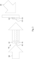
- Fig. 2 is a schematic diagram illustrating a spatial stepped exposure method according to some embodiments of the present disclosure.
- a photopolymer is exposed with two light beams (i.e., a reference beam RB and a signal beam SB) of the red light R, the green light G, or the blue light B in difference incidence directions from the opposite sides of the photopolymer.
- the photopolymer may include monomer, polymer, photo-initiator, and binder.
- the photo-initiator receives photons to generate radicals, so that the monomers begin to polymerize (i.e., polymerization).
- phase gratings i.e., the holographic gratings of the second diffractive element 122, the third diffractive element 123, and the fourth diffractive element 124) each including bright and dark stripes can be formed, and the photopolymer is transformed to a combination of the second diffractive element 122, the third diffractive element 123, and the fourth diffractive element 124.
- a volume holographic grating can form a transmissive holographic grating or a reflective holographic grating according to different manufacturing methods. Specifically, as shown in Fig. 2 , by exposing the photopolymer with the reference beam RB and the signal beam SB in difference incidence directions from the opposite sides of the photopolymer, the holographic gratings of the second diffractive element 122, the third diffractive element 123, and the fourth diffractive element 124 can be manufactured as reflective diffractive elements.
- the second diffractive element 122, the third diffractive element 123, and the fourth diffractive element 124 can be manufactured as transmissive diffractive elements (i.e., the holographic gratings of the second diffractive element 122, the third diffractive element 123, and the fourth diffractive element 124 are transmissive holographic gratings).
- the first diffractive element 121 is a reflective diffractive element, but the present disclosure is not limited in this regard. In some other embodiments, the first diffractive element 121 may be a transmissive diffractive element.
- the holographic gratings can be formed through a photochemical reaction mechanism and established through a dual-light interference exposure system (e.g., the optical exposure system 200 as shown in Fig. 5 ).
- the sum of the energies of the reference beam RB and the signal beam SB is the total light intensity.
- the ratio of the light intensities of the reference beam RB and the signal beam SB is 1:1.
- I ref represents the light intensity of the reference beam RB
- I sig represents the light intensity of the signal beam SB.
- a specific ratio that conforms to the holographic interference rule can also be used, and the present disclosure is not limited in this regard.
- the exposure time is controlled to reach the dosage required by the holographic photosensitive material (i.e., the photopolymer).
- the required dosages of photopolymer are reached, the gratings are formed.
- the dosages can be calculated by the following equation (2).
- Fig. 3 is a graph showing the relationship between the total dosage received by the photopolymer and the diffraction efficiency of the photopolymer. It should be pointed out that the graph is obtained by exposing the photopolymer to the reference beam RB and the signal beam SB of the blue light B for example.
- the diffraction efficiencies of the second diffractive element 122, the third diffractive element 123, and the fourth diffractive element 124 are about 33%, 50%, and 99%, respectively.
- the exposure dosages needed by the second diffractive element 122, the third diffractive element 123, and the fourth diffractive element 124 are 15 mJ/cm 2 , 18 mJ/cm 2 , and 45 mJ/cm 2 , respectively.
- each of the reference beam RB and the signal beam SB may be modulated to have a flat-top intensity distribution.
- a stepped neural density filter NF is disposed in front of the photopolymer. A side of the photopolymer is exposed to the reference beam RB via the stepped neural density filter NF, and another side of the photopolymer is exposed to the signal beam SB.
- Power Reference represents the power of the reference beam RB
- Power Signal represents the power of the signal beam SB
- ⁇ represents the light transmittance
- r represents the exposure radius.
- Power Reference and Power Signal may be 18 mW and 50 mW, respectively
- r is 1.6 mm
- the exposure time is 5.5 seconds.
- the light transmittances of three gradient intervals of the stepped neural density filter NF which are 8%, 17%, and 96% can be obtained.
- the holographic photosensitive material can be exposed to different dosages in different regions, and finally the second diffractive element 122, the third diffractive element 123, and the fourth diffractive element 124 with a gradient change in diffraction efficiency can be obtained.
- Fig. 4 is a schematic diagram illustrating a sequential stepped exposure method according to some embodiments of the present disclosure.
- the second diffractive element 122 can be formed by exposing to a reference beam RB1 and a signal beam SB1
- the third diffractive element 123 can be formed by exposing to a reference beam RB2 and a signal beam SB2
- the fourth diffractive element 124 can be formed by exposing to a reference beam RB3 and a signal beam SB3.
- the exposure sequence of the second diffractive element 122, the third diffractive element 123, and the fourth diffractive element 124 can be flexibly adjusted as needed.
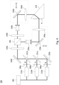
- Fig. 5 is a schematic diagram of an optical exposure system 200 according to some embodiments of the present disclosure.
- the optical exposure system 200 includes three light sources 210a, 210b, 210c configured to emit the red light R, the green light G, and the blue light B, respectively.
- the wavelength band of the red light R projected by the light sources 210a is about 633 nm, but the disclosure is not limited in this regard.
- the wavelength band of the green light G projected by the light sources 210b is about 532 nm, but the disclosure is not limited in this regard.
- the wavelength band of the blue light B projected by the light sources 210c is about 457 nm, but the disclosure is not limited in this regard.
- the light sources 210a, 210b, 210c may be laser diodes, but the disclosure is not limited in this regard.
- the optical exposure system 200 further includes four reflective mirrors 220a, 220b, 220c, 220d, two dichroic mirrors 221a, 221b, two half-wave plates 230a, 230b, a polarizing beam splitter 240, two spatial filters 250a, 250b, two lenses 260a, 260b, a prism 270, and three light valves 280a, 280b, 280c.
- the light valve 280a is optically coupled between the light source 210a and the reflective mirror 220a.
- the light valve 280b is optically coupled between the light source 210b and the dichroic mirror 221a.
- the light valve 280c is optically coupled between the light source 210c and the dichroic mirror 221b.
- the dichroic mirrors 221a, 221b are optically coupled between the reflective mirrors 220a, 220b sequentially.
- the half-wave plate 230a is optically coupled between the reflective mirror 220b and the polarizing beam splitter 240.
- a photopolymer P is attached to a side of the prism 270.
- the polarizing beam splitter 240 is optically coupled to the prism 270 sequentially via the spatial filter 250a, the reflective mirror 220c, the lens 260a, and the photopolymer P.
- the polarizing beam splitter 240 is further optically coupled to the prism 270 sequentially via the half-wave plate 230b, the spatial filter 250b, the reflective mirror 220d, and the lens 260b.
- the light valves 280a, 280b, 280c are configured to respectively allow the red light R, the green light G, and the blue light B to pass through.
- the dichroic mirror 221a is configured to transmit the red light R and reflect the green light G.
- the dichroic mirror 221b is configured to transmit the red light R and the green light G and reflect the blue light B.
- two light beams of the red light R will be generated to reach opposite sides of the photopolymer P when the light source 210a emits the red light R and the light valve 280a allows the red light R pass through
- two light beams of the green light G will be generated to reach the opposite sides of the photopolymer P when the light source 210b emits the green light G and the light valve 280b allows the green light G pass through
- two light beams of the blue light B will be generated to reach the opposite sides of the photopolymer P when the light source 210c emits the blue light B and the light valve 280c allows the blue light B pass through.
- a combination of the light source 210a and the light valve 280a may be regarded as a red light-emitting module
- a combination of the light source 210b and the light valve 280b may be regarded as a green light-emitting module
- a combination of the light source 210c and the light valve 280c may be regarded as a blue light-emitting module.
- the light valves 280a, 280b, 280c are shutters, but the disclosure is not limited in this regard.
- the optical exposure system 200 further includes a controller 290.
- the controller 290 is electrically connected to the light sources 210a, 210b, 210c, and is configured to control the light sources 210a, 210b, 210c to emit the red light R, the green light G, and the blue light B, respectively.
- the light valves 280a, 280b, 280c in Fig. 3 may be omitted.
- light source 210a may be regarded as a red light-emitting module
- the light source 210b may be regarded as a green light-emitting module
- the light source 210c may be regarded as a blue light-emitting module.
- each of the second diffractive element 122, the third diffractive element 123, and the fourth diffractive element 124 may be formed with three holographic gratings of the red light R, the green light G, and the blue light B intersect each other.
- the required dosage of the red light R may be about 7 mJ/cm 2
- the required dosage of the green light G may be about 15 mJ/cm 2
- the required dosage of the blue light B may be about 18 mJ/cm 2 .
- the required dosage of the red light R may be about 10 mJ/cm 2
- the required dosage of the green light G may be about 18 mJ/cm 2
- the required dosage of the blue light B may be about 30 mJ/cm 2
- the required dosage of the red light R may be about 24 mJ/cm 2
- the required dosage of the green light G may be about 45 mJ/cm 2
- the required dosage of the blue light B may be about 50 mJ/cm 2 .
- the prism 270 on which the photopolymer P is attached is movable in a direction (e.g., the vertical direction in Fig. 5 ).
- a direction e.g., the vertical direction in Fig. 5
- the photopolymer P is exposed to a reference beam RB1 and a signal beam SB1 at the same time to form at last one holographic grating of the second diffractive element 122.
- the prism 270 moves down in the direction, and then the photopolymer P is exposed to a reference beam RB2 and a signal beam SB2 at the same time to form at last one holographic grating of the third diffractive element 123.
- the prism 270 further moves down in the direction, and then the photopolymer P is exposed to a reference beam RB3 and a signal beam SB3 at the same time to form at last one holographic grating of the fourth diffractive element 124.
- Fig. 6 is a schematic diagram of an optical exposure system 300 according to some embodiments of the present disclosure.
- the optical exposure system 300 includes all the components of the optical exposure system 200 shown in Fig. 5 .
- the prism 270 of the optical exposure system 300 is stationary, a first combination of the reflective mirror 220c and the lens 260a is movable in a first direction (e.g., the vertical direction in Fig. 6 ), and a second combination of the reflective mirror 220d and the lens 260b is movable in a second direction (e.g., the horizontal direction in Fig. 6 ).
- a first direction e.g., the vertical direction in Fig. 6
- a second combination of the reflective mirror 220d and the lens 260b is movable in a second direction (e.g., the horizontal direction in Fig. 6 ).
- a first direction e.g., the vertical direction in Fig. 6
- a second combination of the reflective mirror 220d and the lens 260b
- the photopolymer P is exposed to a reference beam RB1 and a signal beam SB1 at the same time to form at last one holographic grating of the second diffractive element 122.
- the first combination moves up in the first direction and the second combination moves left in the second direction, and then the photopolymer P is exposed to a reference beam RB2 and a signal beam SB2 at the same time to form at last one holographic grating of the third diffractive element 123.
- the first combination further moves up in the first direction and the second combination further moves left in the second direction, and then the photopolymer P is exposed to a reference beam RB3 and a signal beam SB3 at the same time to form at last one holographic grating of the fourth diffractive element 124.
- the second diffractive element 122, the third diffractive element 123, and the fourth diffractive element 124 are sequentially formed. Specifically, the formation of the third diffractive element 123 is performed after the formation of the three holographic gratings of the second diffractive element 122 are finished, and then the formation of the fourth diffractive element 124 is performed after the formation of the three holographic gratings of the third diffractive element 123 are finished.
- the holographic gratings of the red light R, the green light G, and the blue light B are sequentially formed. Specifically, the formation of the holographic gratings of the green light G of the second diffractive element 122, the third diffractive element 123, and the fourth diffractive element 124 is performed after the formation of the three holographic gratings of the red light R are finished, and the formation of the holographic gratings of the blue light B is performed after the formation of the three holographic gratings of the green light G finished.
- the diffraction efficiencies of the second diffractive element and the third diffractive element increase as the energy of the totally reflected light decreases.
- the second diffractive element and the third diffractive element having different diffraction efficiencies can provide a wider eyebox range, and this range can provide a more uniform light intensity. It allows users to see uniformly bright and dark image content when laterally moving their eyes relative to the waveguide device and the optical engine.
Landscapes
- Physics & Mathematics (AREA)
- General Physics & Mathematics (AREA)
- Optics & Photonics (AREA)
- Engineering & Computer Science (AREA)
- Microelectronics & Electronic Packaging (AREA)
- Manufacturing & Machinery (AREA)
- Diffracting Gratings Or Hologram Optical Elements (AREA)
- Optical Couplings Of Light Guides (AREA)
- Optical Integrated Circuits (AREA)
Applications Claiming Priority (2)
| Application Number | Priority Date | Filing Date | Title |
|---|---|---|---|
| US202263403873P | 2022-09-06 | 2022-09-06 | |
| EP23195658.2A EP4336242A1 (fr) | 2022-09-06 | 2023-09-06 | Dispositif de guide d'ondes et moteur optique |
Related Parent Applications (1)
| Application Number | Title | Priority Date | Filing Date |
|---|---|---|---|
| EP23195658.2A Division EP4336242A1 (fr) | 2022-09-06 | 2023-09-06 | Dispositif de guide d'ondes et moteur optique |
Publications (2)
| Publication Number | Publication Date |
|---|---|
| EP4439155A2 true EP4439155A2 (fr) | 2024-10-02 |
| EP4439155A3 EP4439155A3 (fr) | 2025-01-15 |
Family
ID=87934126
Family Applications (2)
| Application Number | Title | Priority Date | Filing Date |
|---|---|---|---|
| EP24186947.8A Pending EP4439155A3 (fr) | 2022-09-06 | 2023-09-06 | Procédés d'exposition étagée spatiale et séquentielle pour la fabrication d'éléments diffractants d'un dispositif guide d'ondes ou d'un moteur optique |
| EP23195658.2A Withdrawn EP4336242A1 (fr) | 2022-09-06 | 2023-09-06 | Dispositif de guide d'ondes et moteur optique |
Family Applications After (1)
| Application Number | Title | Priority Date | Filing Date |
|---|---|---|---|
| EP23195658.2A Withdrawn EP4336242A1 (fr) | 2022-09-06 | 2023-09-06 | Dispositif de guide d'ondes et moteur optique |
Country Status (4)
| Country | Link |
|---|---|
| US (1) | US20240077677A1 (fr) |
| EP (2) | EP4439155A3 (fr) |
| CN (1) | CN117666141A (fr) |
| TW (1) | TWI871756B (fr) |
Family Cites Families (11)
| Publication number | Priority date | Publication date | Assignee | Title |
|---|---|---|---|---|
| US7573640B2 (en) * | 2005-04-04 | 2009-08-11 | Mirage Innovations Ltd. | Multi-plane optical apparatus |
| JP6437435B2 (ja) * | 2012-08-13 | 2018-12-12 | コベストロ、ドイチュラント、アクチエンゲゼルシャフトCovestro Deutschland Ag | 出力結合素子を有する導光板 |
| DE102013219625B3 (de) * | 2013-09-27 | 2015-01-22 | Carl Zeiss Ag | Brillenglas für eine auf den Kopf eines Benutzers aufsetzbare und ein Bild erzeugende Anzeigevorrichtung sowie Anzeigevorrichtung mit einem solchen Brillenglas |
| JP2016206480A (ja) * | 2015-04-24 | 2016-12-08 | セイコーエプソン株式会社 | 回折光学素子の製造方法及び画像表示装置 |
| US10877214B2 (en) * | 2018-05-04 | 2020-12-29 | Facebook Technologies, Llc | Diffraction gratings for beam redirection |
| EP3663833A3 (fr) * | 2018-12-05 | 2020-07-29 | HTC Corporation | Dispositif de guide d'ondes et moteur optique |
| US20200355862A1 (en) * | 2019-05-08 | 2020-11-12 | Facebook Technologies, Llc | Spatial deposition of resins with different functionality on different substrates |
| US20210055551A1 (en) * | 2019-08-23 | 2021-02-25 | Facebook Technologies, Llc | Dispersion compensation in volume bragg grating-based waveguide display |
| CN114415275B (zh) * | 2020-10-28 | 2024-11-26 | 杭州海康威视数字技术股份有限公司 | 曝光设备及近眼显示设备 |
| EP4260127A1 (fr) * | 2020-12-10 | 2023-10-18 | Snap, Inc. | Dispositif optique |
| CN113075793B (zh) * | 2021-04-06 | 2023-06-02 | 业成科技(成都)有限公司 | 显示装置及其操作方法 |
-
2023
- 2023-09-06 EP EP24186947.8A patent/EP4439155A3/fr active Pending
- 2023-09-06 CN CN202311143667.2A patent/CN117666141A/zh active Pending
- 2023-09-06 EP EP23195658.2A patent/EP4336242A1/fr not_active Withdrawn
- 2023-09-06 US US18/461,525 patent/US20240077677A1/en active Pending
- 2023-09-06 TW TW112133857A patent/TWI871756B/zh active
Also Published As
| Publication number | Publication date |
|---|---|
| TWI871756B (zh) | 2025-02-01 |
| CN117666141A (zh) | 2024-03-08 |
| EP4336242A1 (fr) | 2024-03-13 |
| EP4439155A3 (fr) | 2025-01-15 |
| US20240077677A1 (en) | 2024-03-07 |
| TW202411731A (zh) | 2024-03-16 |
Similar Documents
| Publication | Publication Date | Title |
|---|---|---|
| US11474347B2 (en) | Waveguide and devices for data reflection | |
| US20200183162A1 (en) | Waveguide device and optical engine | |
| CN108139593B (zh) | 具有反射转向阵列的成像光引导 | |
| US11561393B2 (en) | Light guide plate and image display device | |
| CN111566571A (zh) | 波导单元格中全息光栅高吞吐量记录的系统和方法 | |
| CN104423042A (zh) | 光学器件及图像显示装置 | |
| EP3444527B1 (fr) | Plaque de guidage de lumière, unité de rétroéclairage et appareil d'affichage holographique comprenant l'unité de rétroéclairage | |
| JP2019507370A (ja) | 反射型転換アレイを有する結像光ガイド | |
| CN115509006B (zh) | 光学设备及电子设备 | |
| CN112462519A (zh) | 一种出光均匀的光栅波导显示装置 | |
| WO2023011199A1 (fr) | Module de dispositif d'affichage, dispositif d'affichage et procédé d'affichage d'image | |
| EP3995881A1 (fr) | Dispositif de guide d'ondes et moteur optique | |
| EP4439155A2 (fr) | Procédés d'exposition étagée spatiale et séquentielle pour la fabrication d'éléments diffractants d'un dispositif guide d'ondes ou d'un moteur optique | |
| JPH11326821A (ja) | 虚像観察光学系 | |
| EP4446821A1 (fr) | Procédé de fabrication d'un élément optique et système d'exposition optique | |
| US12619087B2 (en) | Method of manufacturing optical element and projection device | |
| US20230324593A1 (en) | Method of manufacturing optical element and optical exposure system | |
| US20250189812A1 (en) | Light guide plate and image display device | |
| US20240118552A1 (en) | Method of manufacturing optical element and projection device | |
| CN116348804B (zh) | 体光栅中的折射率廓线的变迹 | |
| US20250355156A1 (en) | Waveguide device and optical device using the same | |
| CN223217738U (zh) | 显示装置及抬头显示系统 | |
| CN222506666U (zh) | 一种抬头显示系统及设备、图像光束耦出装置 | |
| Weng et al. | 3‐3: study on the field of view properties for a holographic waveguide display system | |
| CN119317861A (zh) | 投影基板以及投影基板的制造方法 |
Legal Events
| Date | Code | Title | Description |
|---|---|---|---|
| PUAI | Public reference made under article 153(3) epc to a published international application that has entered the european phase |
Free format text: ORIGINAL CODE: 0009012 |
|
| STAA | Information on the status of an ep patent application or granted ep patent |
Free format text: STATUS: REQUEST FOR EXAMINATION WAS MADE |
|
| 17P | Request for examination filed |
Effective date: 20240705 |
|
| AC | Divisional application: reference to earlier application |
Ref document number: 4336242 Country of ref document: EP Kind code of ref document: P |
|
| AK | Designated contracting states |
Kind code of ref document: A2 Designated state(s): AL AT BE BG CH CY CZ DE DK EE ES FI FR GB GR HR HU IE IS IT LI LT LU LV MC ME MK MT NL NO PL PT RO RS SE SI SK SM TR |
|
| REG | Reference to a national code |
Ref country code: DE Ref legal event code: R079 Free format text: PREVIOUS MAIN CLASS: G02B0027420000 Ipc: G02B0027000000 |
|
| PUAL | Search report despatched |
Free format text: ORIGINAL CODE: 0009013 |
|
| STAA | Information on the status of an ep patent application or granted ep patent |
Free format text: STATUS: EXAMINATION IS IN PROGRESS |
|
| AK | Designated contracting states |
Kind code of ref document: A3 Designated state(s): AL AT BE BG CH CY CZ DE DK EE ES FI FR GB GR HR HU IE IS IT LI LT LU LV MC ME MK MT NL NO PL PT RO RS SE SI SK SM TR |
|
| RIC1 | Information provided on ipc code assigned before grant |
Ipc: G02B 6/12 20060101ALN20241206BHEP Ipc: G03H 1/04 20060101ALN20241206BHEP Ipc: G02B 27/42 20060101ALI20241206BHEP Ipc: G02B 5/18 20060101ALI20241206BHEP Ipc: G02B 27/01 20060101ALI20241206BHEP Ipc: G02B 27/00 20060101AFI20241206BHEP |
|
| 17Q | First examination report despatched |
Effective date: 20250103 |