EP4439178A1 - Système et procédé pour appliquer des indices sans impression sur des plaques d'impression flexographique numériques à travers un masque non imagé - Google Patents
Système et procédé pour appliquer des indices sans impression sur des plaques d'impression flexographique numériques à travers un masque non imagé Download PDFInfo
- Publication number
- EP4439178A1 EP4439178A1 EP23164991.4A EP23164991A EP4439178A1 EP 4439178 A1 EP4439178 A1 EP 4439178A1 EP 23164991 A EP23164991 A EP 23164991A EP 4439178 A1 EP4439178 A1 EP 4439178A1
- Authority
- EP
- European Patent Office
- Prior art keywords
- layer
- printing
- lams
- oxygen barrier
- liquid fluid
- Prior art date
- Legal status (The legal status is an assumption and is not a legal conclusion. Google has not performed a legal analysis and makes no representation as to the accuracy of the status listed.)
- Withdrawn
Links
Images

Classifications
-
- G—PHYSICS
- G03—PHOTOGRAPHY; CINEMATOGRAPHY; ANALOGOUS TECHNIQUES USING WAVES OTHER THAN OPTICAL WAVES; ELECTROGRAPHY; HOLOGRAPHY
- G03F—PHOTOMECHANICAL PRODUCTION OF TEXTURED OR PATTERNED SURFACES, e.g. FOR PRINTING, FOR PROCESSING OF SEMICONDUCTOR DEVICES; MATERIALS THEREFOR; ORIGINALS THEREFOR; APPARATUS SPECIALLY ADAPTED THEREFOR
- G03F7/00—Photomechanical, e.g. photolithographic, production of textured or patterned surfaces, e.g. printing surfaces; Materials therefor, e.g. comprising photoresists; Apparatus specially adapted therefor
- G03F7/20—Exposure; Apparatus therefor
- G03F7/2022—Multi-step exposure, e.g. hybrid; backside exposure; blanket exposure, e.g. for image reversal; edge exposure, e.g. for edge bead removal; corrective exposure
-
- G—PHYSICS
- G03—PHOTOGRAPHY; CINEMATOGRAPHY; ANALOGOUS TECHNIQUES USING WAVES OTHER THAN OPTICAL WAVES; ELECTROGRAPHY; HOLOGRAPHY
- G03F—PHOTOMECHANICAL PRODUCTION OF TEXTURED OR PATTERNED SURFACES, e.g. FOR PRINTING, FOR PROCESSING OF SEMICONDUCTOR DEVICES; MATERIALS THEREFOR; ORIGINALS THEREFOR; APPARATUS SPECIALLY ADAPTED THEREFOR
- G03F7/00—Photomechanical, e.g. photolithographic, production of textured or patterned surfaces, e.g. printing surfaces; Materials therefor, e.g. comprising photoresists; Apparatus specially adapted therefor
- G03F7/20—Exposure; Apparatus therefor
- G03F7/2002—Exposure; Apparatus therefor with visible light or UV light, through an original having an opaque pattern on a transparent support, e.g. film printing, projection printing; by reflection of visible or UV light from an original such as a printed image
- G03F7/2014—Contact or film exposure of light sensitive plates such as lithographic plates or circuit boards, e.g. in a vacuum frame
- G03F7/2016—Contact mask being integral part of the photosensitive element and subject to destructive removal during post-exposure processing
- G03F7/202—Masking pattern being obtained by thermal means, e.g. laser ablation
-
- G—PHYSICS
- G03—PHOTOGRAPHY; CINEMATOGRAPHY; ANALOGOUS TECHNIQUES USING WAVES OTHER THAN OPTICAL WAVES; ELECTROGRAPHY; HOLOGRAPHY
- G03F—PHOTOMECHANICAL PRODUCTION OF TEXTURED OR PATTERNED SURFACES, e.g. FOR PRINTING, FOR PROCESSING OF SEMICONDUCTOR DEVICES; MATERIALS THEREFOR; ORIGINALS THEREFOR; APPARATUS SPECIALLY ADAPTED THEREFOR
- G03F7/00—Photomechanical, e.g. photolithographic, production of textured or patterned surfaces, e.g. printing surfaces; Materials therefor, e.g. comprising photoresists; Apparatus specially adapted therefor
- G03F7/20—Exposure; Apparatus therefor
- G03F7/24—Curved surfaces
Definitions
- a typical flexographic (flexo) photopolymer plate workflow may comprise the following steps:
- plate precursor may be used herein to refer to any form of the plate in process prior to achieving its final form ready to receive and transmit ink. In general, however, at least the relief structures of the finished plate take a near final form after the uncured polymer removal step, despite one or more additional processes remaining. At times, the term “plate” may also be used herein to refer to the plate precursor as a shorthand reference, but those of skill in the art will understood the actual state of the plate in the overall process.
- One aspect of the invention relates to a method for creating non-printing indicia on a flexographic printing plate, wherein the non-printing indicia comprising structures having a non-printing elevation above a floor of the plate.
- the method includes the steps of providing a photopolymer printing plate precursor having a front side, a back side opposite the front side, and a Laser Ablateable Mask system (LAMs) layer disposed over the front side; disposing on the LAMs layer an oxygen barrier having a pattern defining the non-printing indicia; and exposing the back side of the plate precursor to actinic radiation while the oxygen barrier remains disposed on the LAMs layer.
- LAMs Laser Ablateable Mask system
- Embodiments of the method may include imaging the LAMs layer by laser ablating openings in the LAMs layer corresponding to a desired image to be formed by printing structures on the front side of the plate prior to the exposure step. Such an embodiment may further include, after or during the back side exposure step, performing a front side exposure step comprising exposing the photopolymer printing plate precursor to actinic radiation through the openings in the LAMs layer.
- the oxygen barrier may comprise a planar layer defining the pattern, such as a foil or a sticker, or the oxygen barrier may comprise a 3-dimensional object having elevated relief structures defining the pattern with gaps between adjacent relief structures that allow airflow therebetween, wherein the 3-dimensional object is disposed on the LAMs layer with outward surfaces of the elevated relief structure facing the LAMs layer.
- a 3-dimensional object may comprise a portion of a finished printing plate having structures elevated above a floor thereof that define the pattern.
- Embodiments may also include disposing the oxygen barrier by applying a liquid fluid, such as oil, water, ink, or a combination thereof, to the LAMs layer. The liquid fluid may be applied between the LAMs layer and the 3-dimensional or planar object that defines the pattern.
- the liquid fluid as applied or after evaporation of a volatile component to leave a dried residue, may solely define the pattern.
- the liquid fluid may be applied using an inkjet printer or a spray nozzle, via a marking pen or a stamp, or by applying a stencil to the LAMs layer, applying the liquid fluid over the stencil, and removing the stencil.
- the intensity and corresponding duration for the actinic radiation exposure step may be selected for improving or optimizing formation of the non-printing indicia relative to a operable intensity associated with a different (typically shorter) corresponding duration.
- the system includes a photopolymer printing plate precursor having a front side, a back side opposite the front side, and a Laser Ablateable Mask system (LAMs) layer disposed over the front side; a back side exposure system configured to expose the back side of the plate precursor to actinic radiation; and an oxygen barrier having a pattern that defines the non-printing indicia disposed on the LAMs layer.
- LAMs Laser Ablateable Mask system
- the oxygen barrier may comprise a planar layer defining the pattern or a 3-dimensional object having elevated relief structures defining the pattern with gaps between adjacent relief structures that allow airflow therebetween, wherein the 3-dimensional object is disposed on the LAMs layer with outward surfaces of the elevated relief structure facing the LAMs layer.
- the system may further include a liquid fluid disposed between the LAMs layer and the outward surfaces of the elevated relief structure of 3-dimensional object.
- the oxygen barrier comprises a liquid fluid or a dried residue remaining from a liquid fluid from which a volatile component has evaporated.
- the system may further include an applicator for applying the liquid fluid, such as an inkjet printer, a marking pen, a stamp, or a spray nozzle.
- an inkjet printer having a print head mounted on a carriage of an exposure system.
- the system may include an inkjet printer comprising a print head mounted on an imaging system.
- systems that may be particularly suitable for practicing aspects of the invention may include the Esko ® XPS, the XSYS ThermoFlexX Catena-E system, and certain bank exposure systems having one bank of tubes for front and another bank for back exposure (such as, e.g., a Cyrel ® 3000 ETL-I system).
- Esko ® XPS the XSYS ThermoFlexX Catena-E system
- certain bank exposure systems having one bank of tubes for front and another bank for back exposure (such as, e.g., a Cyrel ® 3000 ETL-I system).
- aspects of the invention relate to the creation of non-printing structures on the plate floor by placing an oxygen-blocking barrier on top of the LAMs layer of a digital flexographic printing plate.
- exemplary methods as described herein utilize relatively simple tools like stamps or stencils that apply or admit the application of an oxygen blocking ink or other oxygen blocking liquid fluid to the LAMs layer of the printing plate.
- stamps or stencils that apply or admit the application of an oxygen blocking ink or other oxygen blocking liquid fluid to the LAMs layer of the printing plate.
- Plate ID information such as brand logos or watermarks with plate information, such as production day or customer name, on the plate.
- the invention is not limited to any specific content for the non-printing indicia so created, but exemplary content may include alphanumeric characters, non-text graphics, machine readable code, one or more lines, or a combination thereof, some or all of which may be in a repeating pattern.
- the non-printing indicia in any of the foregoing forms may embody information including job number, separation color, version, date, or a combination thereof.
- the indicia may comprise branding information.
- the non-printing indicia may comprise alignment indicia for orienting the plate relative to the element of plate processing equipment.
- human readable alphanumeric information is also machine readable by a reader equipped with suitable optical character recognition (OCR) functionality, and that the hardware and software for providing such functionality is well known in the art.
- OCR optical character recognition
- Machine vision systems and human operators alike can also be trained to read non-alphanumeric graphic symbols to convey information that can be universally understood (e.g. the graphic symbols denoting recyclable materials or laundry care recommendations).
- indica and “machine readable” are intended to be broadly interpreted to include, without limitation, in addition to the other types of indicia discussed in detail herein, printed or otherwise visible alphanumeric or graphical information configured to be read and comprehended by human operators as well as machines, as well as combinations of indicia that are exclusively machine readable with indicia that is both human and machine readable.
- machine-readable indicia that is also at least partially human readable, is that an experienced human operator may be able to process and act upon at least some codes faster than it would take that same operator to enlist the assistance of a machine.
- process information may be stored directly or indirectly in the indicia, such as may be embodied in a QR code, although indicia used for providing such information is not limited to any particular type of code.
- at least one variable operating parameter may be embodied in the indicia or stored in computer memory at a unique, machine-accessible address embodied in the indicia.
- process parameters for one or more stages of plate processing are embodied directly in the code such that each individual processing unit can derive instructions directly from the code on the plate without having to connect to a network.
- the code may comprise a computer storage address where such process information is stored and may be used in conjunction with a reader configured to read the information embodied in the indicia, connect to the storage address embedded in the information such as via a hyperlink, read the information from the storage address, and communicating relevant stored information to the processing machine.
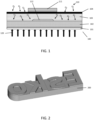
- the mechanism operative to perform the method entails blocking the entrance of oxygen from the surrounding air into the photopolymer during backside curing. This principle is depicted in FIG. 1 .
- FIG. 1 depicts a flexographic, photopolymer plate precursor 100, comprising dimensionally stable backside foil 101, photopolymer layer 102 to be cured by actinic radiation 120 to build the plate floor after the plate has been completely processed, another layer of non-cured polymer 103 that is removed during processing except for cured portions thereof that form relief structures elevated above the floor of the plate, and the LAMs layer 104 disposed over the non-cured polymer.
- laser ablation of the LAMs layer in an imaging step and subsequent front side curing of photopolymer 103 in a subsequent front side curing step results in cured portions of the photopolymer corresponding to a desired image, which cured portions remain in the uncured polymer removal step to create relief structures.
- Relief structures having a printing elevation are configured to receive ink, whereas relief structures having a non-printing elevation may be used for support of printing structures or as non-printing indicia, as described in the background section herein. It should be noted that while specific methods for forming some non-printing indicia are disclosed and described in detail herein, this disclosure does not preclude the use of other methods for forming other non-printing indicia on the same plate.
- oxygen barriers defining one or more patterns that form alphanumeric letters, numbers, or codes thus may be used for creating three-dimensional, non-printing structures on the plate floor.
- FIG. 2 depicts a three-dimensional Esko logo 200 (i.e. four letters in stylized form that are arranged to form the brand name "Esko"), printed on a 3-D printer.
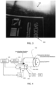
- FIG. 3 is a photograph of structures having a printing elevation of about 0.54 mm at or near the top of the plate in the form of a first Esko logo 300, and a second Esko logo 310 formed by structures having a non-printing elevation of about 25 ⁇ m.
- the plate is an NEF 114 (i.e. 1.14 mm thick) plate with a floor thickness (including the back side substrate) of 0.6 mm.
- the non-printing indicia may be applied through non-imaged portions of the LAMs during a UV back exposure step, such as for example, by placing an already-fully-processed flexo plate with the printing side facing the LAMs layer.
- the relief formed between the printing structures and floor, with the printing structures disposed adjacent the LAMs layer create gaps into which the oxygen can flow during processing.
- 3D structures e.g. 3D printed structures
- Oxygen barriers may also be disposed as planar layers using marker pens, metal foils, stickers, or by applying oxygen blocking liquid fluid.
- the oxygen-blocking fluid such as oil, water, or ink may be used for improving the oxygen-blocking effect of three-dimensional objects, such as the object depicted in FIG. 2 , when the contact surface of the object is slightly wettened with the fluid.
- the oxygen-blocking fluid may solely form the oxygen barrier.
- the oxygen-blocking fluid may be applied as a liquid that dries.
- liquid refers to any non-gas fluid, and may refer to fluids that also contain particulates or non-liquid components, such as fluids comprising a volatile component, such that the applied liquid evaporates, leaving only a dry residue.
- the oxygen blocking fluid may be applied with a stamp, through openings in a stencil, or by inkjet printing or ink spraying.
- a stencil is a type of mask typically comprising a planar sheet with openings therein, and an exemplary process comprises applying the stencil to the surface of the LAMs layer, applying the fluid over the stencil so that the fluid becomes disposed on the LAMs layer in the areas defined by the stencil, and then removing the stencil.
- stencil as used herein is not limited to any particular type of mask construction and may be interpreted to refer to any type of temporary mask that is applied during a fluid application step, and then removed.
- An exemplary method and system may include using a stamp bearing the production date or production site name that places oxygen blocking ink on the LAMs, preferably in a predetermined, repeatable area.
- the stamp may be manually applied by a human user or applied automatically by a machine.
- Another exemplary method and system may include using an inkjet head (for example, mounted on a same movable carriage as a front exposure head in an exposure system or inside a digital imager for laser-ablating the LAMs layer), which prints information on the LAMs layer with oxygen-blocking ink.
- FIG. 4 depicts an exemplary drum (e.g. imager) embodiment.
- imagers typically comprise a drive mechanism 410 (such as a motor and a transmission system, including gearing, belt drives, or the like, not shown) rotate drum 402 in a transverse, circumferential direction about an axis of rotation and advances a carriage 404, on which is mounted the imaging apparatus (e.g. a laser for ablating the LAMs layer).
- the carriage moves in a longitudinal (axial) direction parallel to the drum rotation axis, controlled by control system 420 and powered by power supply 430.
- Printing plate 406 may be in the form of a sleeve, or may be rectangular sheet, with the drum configured to hold opposite edges of the sheet in place with any one of various clamping systems known in the art, while the drum rotates. The mechanisms and details of operation of such imaging systems is well known in the art and not explained here further.
- an additional inkjet printhead 440 is also disposed on the carriage and connected to a source of oxygen-blocking ink 442 and a controller 444 for controlling the deposition of oxygen-blocking ink in accordance with the printhead location based upon instructions stored in memory 446 (e.g. an the form of an image defining where ink should and should not be applied), which instructions (e.g.
- the carriage bearing the inkjet head may have a travel limited to a portion of the plate less than the full area of the plate (e.g. less than the full longitudinal dimension of the plate.
- FIG. 5 depicts a plan view of an exemplary exposure system embodiment 500 comprising a substrate 502 (i.e. typically glass through which back-side exposure is transmitted) for holding the plate.
- Carriage 510 is configured to traverse the substrate along the X direction along arrow A in a first path from a first position 512 to a second position 514, and then return back to the first position in the direction of arrow B in a second path.
- the envelope of travel of carriage 510 is outlined by box 516 marked by a first style of dashed lines.
- front exposure actinic radiation is emitted during the traversal in the first path, but not during the traversal in the second path.
- the front side and back side exposure systems are linked to one another and are spaced apart a predetermined distance to cause the back exposure to be followed by a predetermined, repeatable delay before the front back exposure, and/or may be configured to perform one or more back-exposure only steps, as is further described in U.S. Pat. No. 10,732,507 , titled PROCESS AND APPARATUS FOR CONTROLLED EXPOSURE OF FLEXOGRAPHIC PRINTING PLATES AND ADJUSTING THE FLOOR THEREOF, commonly owned by the applicant of the present application and incorporated herein by reference.
- the present disclosure is not limited to any particular exposure method or system, and the details of various exposure systems are well known in the art and are not detailed further herein.
- Embodiments of the invention as described herein include inkjet printer head 520 connected to a source of ink (not shown) and configured to scan the plate along the X and Y direction in a rastering fashion along the path of arrows C and D starting from a storage position 522, moving within the envelope defined by box 524 (marked by dashed lines different than those of box 516) in accordance with instructions provided by a control mechanism (not shown) guided as to where to dispense the oxygen-blocking ink in accordance with instructions stored in memory (not shown).
- a control mechanism not shown
- backside exposure is provided from underneath exposure glass 502, and then frontside exposure is provided.
- the back side exposure step may be independent of the front side exposure.
- the source of ink, controller for the inkjet print head, and memory for storage of instructions may be configured in the same manner as depicted schematically in FIG. 4 .
- the inkjet head may be disposed on the same structure as the exposure head, particularly in systems with rastering front exposure heads, such that the front exposure head and inkjet print head move in tandem, typically with only one of the exposure head or inkjet head operational at a time.
- FIGS. 4 and 5 are only exemplary, and the invention is not limited to any particular structure for mounting the fluid applicator to a drum or flatbed system, or to any particular type of fluid applicator.
- the photopolymer curing process is often a competition between polymer chain growth and oxygen inhibition. Therefore, the effect described herein may be controlled or influenced by the amount of UV energy provided within a given time.
- UV energy intensity and exposure time typically have an inverse ratio to one another wherein as one increases, the other decreases. Decreasing the backside UV intensity such that curing takes relatively longer will make the effect for forming non-printing indicia as described herein stronger (i.e. the non-printing indicia have a greater elevation above the floor and are thus more visible), whereas applying backside curing energy at a relatively higher intensity for a relatively shorter period of time will reduce the effect of oxygen migration and result in a lesser effect.
- the oxygen permeability of the LAMs layer also affects the visibility of the created non-printing structures.
- a LAMs layer that is generally not permeable to oxygen, or plate constructions having dedicated additional oxygen barrier layers, will prevent or lessen the effect, whereas LAMs layers having relatively good permeability will support the effect.
- the plate thickness also has an impact on the strength of the effect.
- Relatively thin plates such as 1.7, 1.14, or 0.76 mm thick flexo plates obtain respectively increasingly visible effects of the methods described herein, all other conditions remaining the same, whereas relatively thicker plates demonstrate less visible effects.
- Systems having relatively unfavorable conditions for creating the effects described herein may benefit from providing relatively larger patterns corresponding to the indicia to be created on the floor for improved visibility, as compared to the size of patterns used in systems with more favorable conditions.
Landscapes
- Physics & Mathematics (AREA)
- General Physics & Mathematics (AREA)
- Optics & Photonics (AREA)
- Manufacture Or Reproduction Of Printing Formes (AREA)
Priority Applications (4)
| Application Number | Priority Date | Filing Date | Title |
|---|---|---|---|
| EP23164991.4A EP4439178A1 (fr) | 2023-03-29 | 2023-03-29 | Système et procédé pour appliquer des indices sans impression sur des plaques d'impression flexographique numériques à travers un masque non imagé |
| EP24734798.2A EP4689802A1 (fr) | 2023-03-29 | 2024-03-29 | Système et procédé d'application d'indices de non-impression sur des plaques d'impression flexographique numériques par l'intermédiaire d'un masque non imagé |
| CN202480021943.4A CN120898178A (zh) | 2023-03-29 | 2024-03-29 | 用于通过非成像掩模在数字柔性版印刷印版上施加非印刷标记的系统和方法 |
| PCT/EP2024/058789 WO2024200832A1 (fr) | 2023-03-29 | 2024-03-29 | Système et procédé d'application d'indices de non-impression sur des plaques d'impression flexographique numériques par l'intermédiaire d'un masque non imagé |
Applications Claiming Priority (1)
| Application Number | Priority Date | Filing Date | Title |
|---|---|---|---|
| EP23164991.4A EP4439178A1 (fr) | 2023-03-29 | 2023-03-29 | Système et procédé pour appliquer des indices sans impression sur des plaques d'impression flexographique numériques à travers un masque non imagé |
Publications (1)
| Publication Number | Publication Date |
|---|---|
| EP4439178A1 true EP4439178A1 (fr) | 2024-10-02 |
Family
ID=85781856
Family Applications (2)
| Application Number | Title | Priority Date | Filing Date |
|---|---|---|---|
| EP23164991.4A Withdrawn EP4439178A1 (fr) | 2023-03-29 | 2023-03-29 | Système et procédé pour appliquer des indices sans impression sur des plaques d'impression flexographique numériques à travers un masque non imagé |
| EP24734798.2A Pending EP4689802A1 (fr) | 2023-03-29 | 2024-03-29 | Système et procédé d'application d'indices de non-impression sur des plaques d'impression flexographique numériques par l'intermédiaire d'un masque non imagé |
Family Applications After (1)
| Application Number | Title | Priority Date | Filing Date |
|---|---|---|---|
| EP24734798.2A Pending EP4689802A1 (fr) | 2023-03-29 | 2024-03-29 | Système et procédé d'application d'indices de non-impression sur des plaques d'impression flexographique numériques par l'intermédiaire d'un masque non imagé |
Country Status (3)
| Country | Link |
|---|---|
| EP (2) | EP4439178A1 (fr) |
| CN (1) | CN120898178A (fr) |
| WO (1) | WO2024200832A1 (fr) |
Citations (6)
| Publication number | Priority date | Publication date | Assignee | Title |
|---|---|---|---|---|
| WO2018172374A1 (fr) | 2017-03-20 | 2018-09-27 | Esko-Graphics Imaging Gmbh | Procédé et appareil pour ajuster le support d'une plaque d'impression flexographique dans un système ou un processus d'exposition contrôlée |
| WO2019192764A1 (fr) | 2018-04-06 | 2019-10-10 | Esko-Graphics Imaging Gmbh | Procédé de marquage persistant de plaques flexo avec des informations de flux de travail et plaques marquées avec celles-ci |
| WO2020043875A1 (fr) | 2018-08-31 | 2020-03-05 | Esko-Graphics Bvba | Forme d'impression photosensible pour procédé d'impression flexographique, comportant des informations visibles et non imprimables, et procédé de préparation de cette forme d'impression |
| US10732507B2 (en) | 2015-10-26 | 2020-08-04 | Esko-Graphics Imaging Gmbh | Process and apparatus for controlled exposure of flexographic printing plates and adjusting the floor thereof |
| WO2020156692A1 (fr) | 2019-02-01 | 2020-08-06 | Esko-Graphics Imaging Gmbh | Système et procédé de marquage persistant de plaques flexographiques et plaques marquées avec celui-ci |
| WO2021069489A1 (fr) | 2019-10-07 | 2021-04-15 | Esko-Graphics Imaging Gmbh | Système et procédé de marquage persistant de plaques flexographiques et plaques marquées avec celui-ci |
-
2023
- 2023-03-29 EP EP23164991.4A patent/EP4439178A1/fr not_active Withdrawn
-
2024
- 2024-03-29 WO PCT/EP2024/058789 patent/WO2024200832A1/fr not_active Ceased
- 2024-03-29 CN CN202480021943.4A patent/CN120898178A/zh active Pending
- 2024-03-29 EP EP24734798.2A patent/EP4689802A1/fr active Pending
Patent Citations (6)
| Publication number | Priority date | Publication date | Assignee | Title |
|---|---|---|---|---|
| US10732507B2 (en) | 2015-10-26 | 2020-08-04 | Esko-Graphics Imaging Gmbh | Process and apparatus for controlled exposure of flexographic printing plates and adjusting the floor thereof |
| WO2018172374A1 (fr) | 2017-03-20 | 2018-09-27 | Esko-Graphics Imaging Gmbh | Procédé et appareil pour ajuster le support d'une plaque d'impression flexographique dans un système ou un processus d'exposition contrôlée |
| WO2019192764A1 (fr) | 2018-04-06 | 2019-10-10 | Esko-Graphics Imaging Gmbh | Procédé de marquage persistant de plaques flexo avec des informations de flux de travail et plaques marquées avec celles-ci |
| WO2020043875A1 (fr) | 2018-08-31 | 2020-03-05 | Esko-Graphics Bvba | Forme d'impression photosensible pour procédé d'impression flexographique, comportant des informations visibles et non imprimables, et procédé de préparation de cette forme d'impression |
| WO2020156692A1 (fr) | 2019-02-01 | 2020-08-06 | Esko-Graphics Imaging Gmbh | Système et procédé de marquage persistant de plaques flexographiques et plaques marquées avec celui-ci |
| WO2021069489A1 (fr) | 2019-10-07 | 2021-04-15 | Esko-Graphics Imaging Gmbh | Système et procédé de marquage persistant de plaques flexographiques et plaques marquées avec celui-ci |
Also Published As
| Publication number | Publication date |
|---|---|
| WO2024200832A1 (fr) | 2024-10-03 |
| EP4689802A1 (fr) | 2026-02-11 |
| CN120898178A (zh) | 2025-11-04 |
Similar Documents
| Publication | Publication Date | Title |
|---|---|---|
| US5495803A (en) | Method of forming a photomask for a printing plate with an ink jet | |
| CA2558037C (fr) | Procede et appareil pour appliquer des marques d'identite sur des documents de securite | |
| CN1214291C (zh) | 合成凸印元件 | |
| US6640713B2 (en) | System and method for recording an image using a laser diode array | |
| US4395946A (en) | Rotary printing presses with inplace laser impression of printing surface | |
| US6648470B2 (en) | Apparatus and method for printing | |
| EP2397327B1 (fr) | Marques d'enregistrement sans impression sur une plaque d'impression | |
| EP2242595B1 (fr) | Plaques d'impression | |
| DE19503951C2 (de) | Verfahren und Vorrichtung für den Tiefdruck | |
| GB2272866A (en) | Non-photographic production of planographic printing plates. | |
| EP0965444A1 (fr) | Système et méthode pour l'impression lithographique utilisant des supports à surface réutilisable | |
| EP4439178A1 (fr) | Système et procédé pour appliquer des indices sans impression sur des plaques d'impression flexographique numériques à travers un masque non imagé | |
| KR101162334B1 (ko) | 자외선 경화형 그라비어 인쇄 장치 | |
| GB2298986A (en) | Method of making printing plates | |
| JPH062427B2 (ja) | 画像記録法及び装置 | |
| NL2034371B1 (en) | Methods and systems for imaging a mask layer | |
| HK1208737A1 (en) | Printable laminates made via liquid photopolymers | |
| JPH1067087A (ja) | トンボマーク形成方法及び印刷版並びにトンボマーク描画装置 | |
| EP1354700A2 (fr) | Procédé pour la manipulation de plaques ou cylindres d'impression ré-utilisables dans les machines d'impression | |
| JP2007086564A (ja) | 印刷版管理方法、ctp装置および印刷機 | |
| JPS6021878B2 (ja) | 投票券発売機 | |
| JP2003182022A (ja) | 印刷装置 | |
| Blunden et al. | The Printing Processes | |
| JPH05278314A (ja) | スタンプ装置 | |
| JPH08110633A (ja) | 印刷版の画像形成方法 |
Legal Events
| Date | Code | Title | Description |
|---|---|---|---|
| PUAI | Public reference made under article 153(3) epc to a published international application that has entered the european phase |
Free format text: ORIGINAL CODE: 0009012 |
|
| STAA | Information on the status of an ep patent application or granted ep patent |
Free format text: STATUS: THE APPLICATION HAS BEEN PUBLISHED |
|
| AK | Designated contracting states |
Kind code of ref document: A1 Designated state(s): AL AT BE BG CH CY CZ DE DK EE ES FI FR GB GR HR HU IE IS IT LI LT LU LV MC ME MK MT NL NO PL PT RO RS SE SI SK SM TR |
|
| STAA | Information on the status of an ep patent application or granted ep patent |
Free format text: STATUS: THE APPLICATION IS DEEMED TO BE WITHDRAWN |
|
| 18D | Application deemed to be withdrawn |
Effective date: 20250403 |