EP4439218A1 - Véhicule de transport sans conducteur - Google Patents
Véhicule de transport sans conducteur Download PDFInfo
- Publication number
- EP4439218A1 EP4439218A1 EP24161142.5A EP24161142A EP4439218A1 EP 4439218 A1 EP4439218 A1 EP 4439218A1 EP 24161142 A EP24161142 A EP 24161142A EP 4439218 A1 EP4439218 A1 EP 4439218A1
- Authority
- EP
- European Patent Office
- Prior art keywords
- transport vehicle
- location
- drop
- environmental sensor
- designed
- Prior art date
- Legal status (The legal status is an assumption and is not a legal conclusion. Google has not performed a legal analysis and makes no representation as to the accuracy of the status listed.)
- Pending
Links
Images






Classifications
-
- G—PHYSICS
- G05—CONTROLLING; REGULATING
- G05D—SYSTEMS FOR CONTROLLING OR REGULATING NON-ELECTRIC VARIABLES
- G05D1/00—Control of position, course, altitude or attitude of land, water, air or space vehicles, e.g. using automatic pilots
- G05D1/60—Intended control result
- G05D1/617—Safety or protection, e.g. defining protection zones around obstacles or avoiding hazards
- G05D1/622—Obstacle avoidance
-
- G—PHYSICS
- G05—CONTROLLING; REGULATING
- G05D—SYSTEMS FOR CONTROLLING OR REGULATING NON-ELECTRIC VARIABLES
- G05D1/00—Control of position, course, altitude or attitude of land, water, air or space vehicles, e.g. using automatic pilots
- G05D1/40—Control within particular dimensions
- G05D1/43—Control of position or course in two dimensions [2D]
-
- B—PERFORMING OPERATIONS; TRANSPORTING
- B66—HOISTING; LIFTING; HAULING
- B66F—HOISTING, LIFTING, HAULING OR PUSHING, NOT OTHERWISE PROVIDED FOR, e.g. DEVICES WHICH APPLY A LIFTING OR PUSHING FORCE DIRECTLY TO THE SURFACE OF A LOAD
- B66F9/00—Devices for lifting or lowering bulky or heavy goods for loading or unloading purposes
- B66F9/06—Devices for lifting or lowering bulky or heavy goods for loading or unloading purposes movable, with their loads, on wheels or the like, e.g. fork-lift trucks
- B66F9/063—Automatically guided
-
- G—PHYSICS
- G01—MEASURING; TESTING
- G01S—RADIO DIRECTION-FINDING; RADIO NAVIGATION; DETERMINING DISTANCE OR VELOCITY BY USE OF RADIO WAVES; LOCATING OR PRESENCE-DETECTING BY USE OF THE REFLECTION OR RERADIATION OF RADIO WAVES; ANALOGOUS ARRANGEMENTS USING OTHER WAVES
- G01S17/00—Systems using the reflection or reradiation of electromagnetic waves other than radio waves, e.g. lidar systems
- G01S17/02—Systems using the reflection of electromagnetic waves other than radio waves
- G01S17/06—Systems determining position data of a target
- G01S17/42—Simultaneous measurement of distance and other co-ordinates
-
- G—PHYSICS
- G01—MEASURING; TESTING
- G01S—RADIO DIRECTION-FINDING; RADIO NAVIGATION; DETERMINING DISTANCE OR VELOCITY BY USE OF RADIO WAVES; LOCATING OR PRESENCE-DETECTING BY USE OF THE REFLECTION OR RERADIATION OF RADIO WAVES; ANALOGOUS ARRANGEMENTS USING OTHER WAVES
- G01S17/00—Systems using the reflection or reradiation of electromagnetic waves other than radio waves, e.g. lidar systems
- G01S17/88—Lidar systems specially adapted for specific applications
- G01S17/93—Lidar systems specially adapted for specific applications for anti-collision purposes
- G01S17/931—Lidar systems specially adapted for specific applications for anti-collision purposes of land vehicles
-
- G—PHYSICS
- G05—CONTROLLING; REGULATING
- G05D—SYSTEMS FOR CONTROLLING OR REGULATING NON-ELECTRIC VARIABLES
- G05D1/00—Control of position, course, altitude or attitude of land, water, air or space vehicles, e.g. using automatic pilots
- G05D1/20—Control system inputs
- G05D1/24—Arrangements for determining position or orientation
- G05D1/242—Means based on the reflection of waves generated by the vehicle
-
- G—PHYSICS
- G05—CONTROLLING; REGULATING
- G05D—SYSTEMS FOR CONTROLLING OR REGULATING NON-ELECTRIC VARIABLES
- G05D1/00—Control of position, course, altitude or attitude of land, water, air or space vehicles, e.g. using automatic pilots
- G05D1/20—Control system inputs
- G05D1/24—Arrangements for determining position or orientation
- G05D1/242—Means based on the reflection of waves generated by the vehicle
- G05D1/2424—Means based on the reflection of waves generated by the vehicle for monitoring a plurality of zones
-
- G—PHYSICS
- G05—CONTROLLING; REGULATING
- G05D—SYSTEMS FOR CONTROLLING OR REGULATING NON-ELECTRIC VARIABLES
- G05D1/00—Control of position, course, altitude or attitude of land, water, air or space vehicles, e.g. using automatic pilots
- G05D1/20—Control system inputs
- G05D1/24—Arrangements for determining position or orientation
- G05D1/243—Means capturing signals occurring naturally from the environment, e.g. ambient optical, acoustic, gravitational or magnetic signals
- G05D1/2435—Extracting 3D information
-
- G—PHYSICS
- G05—CONTROLLING; REGULATING
- G05D—SYSTEMS FOR CONTROLLING OR REGULATING NON-ELECTRIC VARIABLES
- G05D1/00—Control of position, course, altitude or attitude of land, water, air or space vehicles, e.g. using automatic pilots
- G05D1/60—Intended control result
- G05D1/617—Safety or protection, e.g. defining protection zones around obstacles or avoiding hazards
- G05D1/622—Obstacle avoidance
- G05D1/633—Dynamic obstacles
-
- G—PHYSICS
- G05—CONTROLLING; REGULATING
- G05D—SYSTEMS FOR CONTROLLING OR REGULATING NON-ELECTRIC VARIABLES
- G05D1/00—Control of position, course, altitude or attitude of land, water, air or space vehicles, e.g. using automatic pilots
- G05D1/60—Intended control result
- G05D1/65—Following a desired speed profile
-
- G—PHYSICS
- G05—CONTROLLING; REGULATING
- G05D—SYSTEMS FOR CONTROLLING OR REGULATING NON-ELECTRIC VARIABLES
- G05D1/00—Control of position, course, altitude or attitude of land, water, air or space vehicles, e.g. using automatic pilots
- G05D1/60—Intended control result
- G05D1/656—Interaction with payloads or external entities
- G05D1/665—Releasing payloads, e.g. parachutes
-
- G—PHYSICS
- G05—CONTROLLING; REGULATING
- G05D—SYSTEMS FOR CONTROLLING OR REGULATING NON-ELECTRIC VARIABLES
- G05D1/00—Control of position, course, altitude or attitude of land, water, air or space vehicles, e.g. using automatic pilots
- G05D1/60—Intended control result
- G05D1/656—Interaction with payloads or external entities
- G05D1/667—Delivering or retrieving payloads
-
- G—PHYSICS
- G01—MEASURING; TESTING
- G01S—RADIO DIRECTION-FINDING; RADIO NAVIGATION; DETERMINING DISTANCE OR VELOCITY BY USE OF RADIO WAVES; LOCATING OR PRESENCE-DETECTING BY USE OF THE REFLECTION OR RERADIATION OF RADIO WAVES; ANALOGOUS ARRANGEMENTS USING OTHER WAVES
- G01S15/00—Systems using the reflection or reradiation of acoustic waves, e.g. sonar systems
- G01S15/88—Sonar systems specially adapted for specific applications
- G01S15/93—Sonar systems specially adapted for specific applications for anti-collision purposes
- G01S15/931—Sonar systems specially adapted for specific applications for anti-collision purposes of land vehicles
-
- G—PHYSICS
- G05—CONTROLLING; REGULATING
- G05D—SYSTEMS FOR CONTROLLING OR REGULATING NON-ELECTRIC VARIABLES
- G05D2105/00—Specific applications of the controlled vehicles
- G05D2105/20—Specific applications of the controlled vehicles for transportation
- G05D2105/28—Specific applications of the controlled vehicles for transportation of freight
-
- G—PHYSICS
- G05—CONTROLLING; REGULATING
- G05D—SYSTEMS FOR CONTROLLING OR REGULATING NON-ELECTRIC VARIABLES
- G05D2107/00—Specific environments of the controlled vehicles
- G05D2107/70—Industrial sites, e.g. warehouses or factories
-
- G—PHYSICS
- G05—CONTROLLING; REGULATING
- G05D—SYSTEMS FOR CONTROLLING OR REGULATING NON-ELECTRIC VARIABLES
- G05D2107/00—Specific environments of the controlled vehicles
- G05D2107/95—Interior or surroundings of another vehicle
-
- G—PHYSICS
- G05—CONTROLLING; REGULATING
- G05D—SYSTEMS FOR CONTROLLING OR REGULATING NON-ELECTRIC VARIABLES
- G05D2109/00—Types of controlled vehicles
- G05D2109/10—Land vehicles
-
- G—PHYSICS
- G05—CONTROLLING; REGULATING
- G05D—SYSTEMS FOR CONTROLLING OR REGULATING NON-ELECTRIC VARIABLES
- G05D2111/00—Details of signals used for control of position, course, altitude or attitude of land, water, air or space vehicles
- G05D2111/10—Optical signals
- G05D2111/17—Coherent light, e.g. laser signals
Definitions
- the present invention relates to a driverless transport vehicle for transporting and setting down a load.
- Such transport vehicles are used, for example, in industrial processes to transport loads automatically.
- transport vehicles are also referred to as Automated Guided Vehicles (AGVs).
- AGVs Automated Guided Vehicles
- driverless transport vehicles have not yet been used in a fully automated manner to load trucks, truck trailers or swap bodies. Such loading is often still done manually.
- the invention is based on the realization that a very high level of safety can be achieved by double scanning the route to the drop-off location and the drop-off location with two different environmental sensors, i.e. safe operation is enabled. Due to this high level of safety, automated loading of a swap body, for example, can be carried out, as it can be ruled out that, for example, a person is at the drop-off location and is then injured or crushed when the transport vehicle drives in with the load.
- the transport vehicle can be loaded with a load, for example a pallet.
- the transport vehicle then first uses the primary environmental sensor to scan the drop-off location for the load and the area between the drop-off location and the transport vehicle in order to detect any obstacles (e.g. people or objects) that may be present.
- This scanning using the primary environmental sensor already provides a very high level of certainty that, for example, no people are in the endangered areas. If it is now detected that there is no obstacle, the transport vehicle begins to drive to the drop-off location.
- the secondary environmental sensor is activated and checked, for example repeatedly. and/or periodically, the route to the drop-off location and ultimately also the drop-off location for obstacles, i.e. again for people or unwanted objects.
- a reaction can be initiated, which includes, for example, stopping the transport vehicle, slowing the transport vehicle or driving around the obstacle.
- the transport vehicle can continue on its way to the drop-off location under monitoring by the secondary environmental sensor and ultimately unload the load at the drop-off location.
- the primary environmental sensor and the secondary environmental sensor are, in particular, separate sensors, which are preferably also different types of sensors.
- the sensors can therefore be based on different measuring principles, for example.
- the primary environmental sensor and the secondary environmental sensor can be aligned in approximately the same direction, so that they have at least partially overlapping viewing areas or measuring areas.
- the alignment of the environmental sensors can be, for example, to the rear with respect to the transport vehicle, so that, for example, the primary environmental sensor can see through the load, in particular the lifted load.
- the secondary environmental sensor can preferably be attached to a rear end of the transport vehicle, for example to the ends of a fork tine if the transport vehicle is a forklift. By attaching it to the At the rear end, the secondary environmental sensor can detect the travel distance and/or the drop-off location even when the load is lowered.
- the drop-off location can in particular be the space and/or area where the load is to be located after being dropped off by the transport vehicle.
- the drop-off location can accordingly have, for example, the shape and/or size of a pallet transported by the transport vehicle.
- the transport vehicle can in particular comprise a control unit which controls the actions of the transport vehicle mentioned here and which also evaluates the measurement data provided by the environmental sensors.
- the control unit can in particular be coupled to a higher-level automation system via radio, for example WLAN.
- the higher-level automation system can in particular inform the transport vehicle where the drop-off location for a load is, as explained in more detail later.
- the transport vehicle is designed to use the primary environmental sensor to detect neighboring areas of the drop-off location in addition to the drop-off location and to compare the detected neighboring areas with expected neighboring areas.
- the primary environmental sensor (but also the secondary environmental sensor) can detect two-dimensional contours of the drop-off location and the neighboring areas.
- the expected neighboring areas can also include two-dimensional contours, which in particular show the boundary of the drop-off location (e.g. in a top view). The neighboring areas can therefore in particular represent the boundary of the drop-off location.
- the primary environmental sensor is used to record data when the transport vehicle is at a standstill, for example, although it is also possible to record data when driving slowly. If faster sensors become available in the future, it could also be possible to record data at normal speed.
- the transport vehicle is designed to receive the expected neighboring areas from a higher-level automation system.
- the transport vehicle is designed to carry out a plausibility check of the measurement data recorded by the primary environmental sensor when checking for obstacles using the primary environmental sensor.
- the plausibility check serves to better detect any obstacles that may be present and can be based in particular on the expected neighboring areas.
- the transport vehicle is designed to set a tolerance range around the expected neighboring areas during the plausibility check, wherein measuring points outside the tolerance range which lie in front of or behind the expected neighboring areas and/or missing measuring points are considered as an obstacle.
- the expected neighboring areas tell the transport vehicle where, for example, the rear boundary of the drop-off location should be. If an environmental sensor now records measuring points that are in front of the expected rear boundary (and also outside the tolerance range), this suggests that, for example, a person is located there.
- measuring points are outside the tolerance range and behind the expected neighboring area. For example, Assuming that the rear boundary of the drop-off location is formed by a wall or another pallet, no measuring points should be located behind the expected neighboring area. In practice, however, it can happen that, for example, black trouser legs "swallow" a lot of signal, so that the environmental sensor falsely reports that a measuring point is located behind the expected neighboring areas. This in turn can be an indication of an obstacle, so that the transport vehicle must then take countermeasures and, for example, stop.
- Missing measuring points can also indicate that, for example, no measurement was possible due to black trouser legs or the like, although it can be assumed that a measuring point should be present due to the known expected neighboring areas.
- the tolerance range can in particular extend on both sides around a contour of the expected neighboring area and in particular have a predetermined size or width.
- the tolerance range can end 15 cm, 20 cm or 30 cm on both sides of the expected neighboring area.
- the transport vehicle is designed to adapt the detected neighboring areas and the expected neighboring areas to one another, in particular by rotation and displacement.
- the adaptation can be carried out by the vehicle itself, for example by a control unit of the transport vehicle.
- the adaptation can also be carried out by an external unit, whereby the transport vehicle can then receive the result.
- the transport vehicle can, for example, recognize a swap body that is at an angle and which has not been driven up to a loading terminal in a completely straight line.
- the transport vehicle is designed to determine the length of the route to the drop-off location and to monitor the actual route traveled during the journey to the drop-off location using a driving sensor system, in particular one coupled to a wheel or an axle of the transport vehicle.
- the driving sensor system can, for example, determine a distance traveled via the number of wheel revolutions.
- the monitoring by means of the driving sensor system can preferably be safety-oriented, i.e., for example, meet a safety level such as SIL2, SIL3 or SIL4 (SIL for Security Integrity Level).
- a countermeasure can be taken, for example stopping the vehicle or reversing the direction of travel.
- Monitoring the route using the driving sensors provides additional safety so that the transport vehicle does not drive beyond the drop-off location because obstacles outside the drop-off location or behind the drop-off location may not have been detected. This also prevents neighboring objects or barriers from being damaged when driving beyond the drop-off location.
- the transport vehicle is designed to ignore the primary environmental sensor when approaching the drop-off location. This means that the primary environmental sensor is "muted” after the approach to the drop-off location has begun. By “muting”, the primary environmental sensor is switched off, for example, or the measured values of the primary environmental sensor are at least not taken into account and/or further processed.
- the load has to be lowered when driving into a truck or swap body, which often means that the primary environmental sensor is covered by the load, so that the function of the primary environmental sensor is limited. "Muting” can therefore also prevent the lowered load from being recognized as an obstacle.
- the secondary environmental sensor is then activated and evaluated in order to replace and check the primary environmental sensor blocked by the load in this respect.
- the transport vehicle is designed to ignore the secondary environmental sensor when approaching the parking location if the transport vehicle comes closer to the detected and/or expected neighboring areas than a predetermined threshold value. If the transport vehicle approaches the detected and/or expected neighboring areas, the secondary environmental sensor then records measured values from these neighboring areas, which can, for example, lie in a protective field of the secondary environmental sensor. If the secondary environmental sensor detects a measured value or an obstacle in its protective field, this can lead to the transport vehicle stopping, which is undesirable because the load could then not be transported completely to the drop-off location.
- the secondary environmental sensor is also "muted" if the transport vehicle comes so close to the neighboring areas (for example, a neighboring pallet) that, for example, a neighboring pallet would cause a protective field violation.
- the predetermined threshold value can accordingly correspond to the size of the protective field of the secondary environmental sensor.
- the predetermined threshold may correspond to the size of the detection area of the secondary environmental sensor.
- the secondary environmental sensor is preferably only "muted" when the load is almost completely at the set-down location and the secondary The environmental sensor has already detected the remaining area of the drop-off location and has therefore ensured that there are no obstacles (i.e. people or objects) there.
- the transport vehicle is designed to monitor the remaining travel path, in particular solely, using the driving sensors after the secondary environmental sensor has been ignored.
- the relatively small remaining travel path can therefore be monitored solely using the driving sensors, with the load then being placed at the place of delivery after it has been reached.
- the placement can be carried out, for example, by lowering the fork of a forklift truck.
- the primary and/or secondary environmental sensor comprises a 2D or 3D sensor, a laser scanner, a multi-layer laser scanner, a multi-beam scanner, a 3D camera, a radar and/or an ultrasonic sensor.
- the primary environmental sensor is preferably designed as a laser scanner and the secondary environmental sensor is preferably designed as an ultrasonic sensor. In this way, different measuring principles can be used to secure the travel path and the drop-off location.
- the primary environmental sensor may be mounted at a height of approximately 200 mm above the ground and have a single scanning plane parallel to the ground.
- the secondary environmental sensor preferably comprises two individual sensors, each of which is an ultrasonic sensor. Both the primary environmental sensor and the secondary environmental sensor may be rear-facing, for example the two ultrasonic sensors may be mounted at the ends of a fork of the transport vehicle.
- the transport vehicle is an autonomous forklift truck or an autonomous industrial truck.
- the drop-off location is located in a truck or swap body and, before detecting the drop-off location with the primary environmental sensor, the transport vehicle drives to a position outside the truck or swap body from which the drop-off location can be detected with the primary environmental sensor. This means that the transport vehicle initially remains outside the truck or swap body in order to carry out the detection with the primary environmental sensor from outside and to determine the route and the drop-off location.
- a swap body can also be referred to as a swap container, swap body, swap flatbed, swap body bridge, swap box or swap loading container and is an interchangeable load carrier that can, for example, be driven under by a carrier vehicle and can be separated from the carrier vehicle again.
- the load is lifted to detect the drop-off location using the primary environmental sensor in order to enable the primary environmental sensor to see the drop-off location through the load.
- Such lifting is only possible outside the truck or swap body. possible.
- the primary environmental sensor may be covered, so that when entering the truck or swap body, the secondary environmental sensor takes over monitoring the route and the drop-off location.
- All of the process steps and actions of the transport vehicle mentioned here can in particular be carried out automatically, i.e. without human intervention or assistance.
- the transport vehicle can receive the drop-off location by radio, then automatically drive to the swap body in which the drop-off location is located.
- a check for obstacles is carried out using the primary environmental sensor in the manner described.
- a check is then carried out using the secondary environmental sensor, which is also carried out automatically.
- the secondary environmental sensor is muted at the drop-off location and the rest of the positioning of the load at the drop-off location is carried out automatically using the driving sensors.
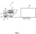
- Fig. 1 shows a driverless transport vehicle, more precisely an autonomous forklift 10.
- the forklift 10 comprises a control unit 12, which controls a drive of the forklift 10.
- the control unit 12 is also equipped with a primary environmental sensor in the form of a laser scanner 14 and with a secondary environmental sensor, which comprises two ultrasonic sensors 16.
- the control unit 12 is also coupled to a driving sensor system 18, which is attached to a wheel of the forklift 10 and detects the movements of the wheel.
- the sensors 14, 16, 18 are coupled to the control unit 12 via data connections 20.
- the forklift 10 comprises a fork tine 22 on which a load 24 can be transported.
- the ultrasonic sensors 16 are arranged at the two ends of the fork tine 22.
- the laser scanner 14 is arranged in such a way that it can look backwards under the load 24 when the load 24 is raised. Accordingly, the laser scanner 24 emits laser pulses 25 backwards during operation in order to detect the surroundings. The laser scanner 24 uses reflected laser pulses (not shown) to determine the light travel time and from this the distance of objects in its measuring range.
- the ultrasonic sensors 16 emit ultrasonic waves 27.
- Fig. 1 also shows a swap body 26 which is arranged on a truck trailer and has been moved to a loading terminal (not shown) so that the autonomous forklift 10 can drive into the swap body 26.
- Fig. 2 The forklift truck 10 and the swap body 26 are now shown in a schematic plan view. It can be seen that several unloaded pallets are already present in the swap body 26.
- the load transported by the forklift truck 10 is also a pallet, which is to be positioned next to the already unloaded pallets 28.
- Fig. 3 now shows that the laser scanner 14 is first used to scan the swap body 26 and the wider surroundings.
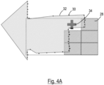
- the laser scanner 14 records a large number of measuring points 30, which form a contour 32.
- the scan with the primary environmental sensor, ie with the laser scanner 14, therefore records both the drop-off location 34 and the route of the forklift truck to the drop-off location 34 and also the surroundings of the drop-off location and the route, ie the neighbouring areas. Accordingly, the contour 32 forms the recorded neighbouring areas.
- the control unit 12 can receive data on the loading status of the swap body 26 from a higher-level automation system via a radio interface (not shown).
- hatched areas are those areas that are reported to the forklift truck 10 by the higher-level automation system as already occupied by pallets.
- a drop-off location 34 is reported to the forklift truck 10.
- the XY coordinates of the contour of the pallets 28 that have already been unloaded can be reported to the forklift truck 10 by the higher-level automation system. The same applies to the coordinates of the drop-off location 34.
- an adjustment of the obtained contour (ie the expected neighboring areas) and the measured contour (ie the detected neighboring areas) is therefore carried out.
- the adjustment is carried out in particular by rotation (d ⁇ ) and displacement (dx, dy).
- the adjustment adjusts the setting-down location 34 and the expected neighboring areas to the reference system of the forklift truck 10.
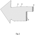
- a tolerance range 36 is set at least in some areas around the expected neighboring areas, as is the case in Fig. 5 shown. In Fig. 5 There are no measuring points 30 that would indicate an obstacle.
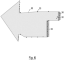
- Fig. 6 there are two measuring points 30 in front of the tolerance area 36, so that it can be assumed that a person is standing in front of the already unloaded pallet 28. In this case, the forklift truck 10 must not drive to the drop-off location 34.
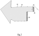
- Fig. 7 shows another variant of the recognition of a person.
- the person is wearing dark trousers, so that the laser scanner 14 receives almost no reflected signal from the trouser legs. In practice, this often leads to measured values being generated further away from the laser scanner 14, which also leads to Fig. 7 is shown. However, since no values can be found in this area because the unloaded pallet 28 is located there, this is also evaluated as the detection of an obstacle (ie a person).
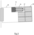
- the ultrasonic sensors 16 remain activated until the forklift 10 has almost reached the drop-off location 34 and the already unloaded pallets 28 come so close to the ultrasonic sensors 16 that the ultrasonic sensors 16 would recognize the unloaded pallets 28 as an obstacle. At this point, the ultrasonic sensors 16 are switched off or ignored, as in Fig. 10 is shown. The forklift truck 10 then travels the remaining distance to the drop-off location 34 based solely on the driving sensors 18, since it is now ensured that there are no obstacles between the load 24 and the pallets 28 that have already been unloaded.
Landscapes
- Engineering & Computer Science (AREA)
- Physics & Mathematics (AREA)
- Radar, Positioning & Navigation (AREA)
- Remote Sensing (AREA)
- General Physics & Mathematics (AREA)
- Automation & Control Theory (AREA)
- Aviation & Aerospace Engineering (AREA)
- Electromagnetism (AREA)
- Transportation (AREA)
- Structural Engineering (AREA)
- Computer Networks & Wireless Communication (AREA)
- Civil Engineering (AREA)
- Life Sciences & Earth Sciences (AREA)
- Geology (AREA)
- Mechanical Engineering (AREA)
- Control Of Position, Course, Altitude, Or Attitude Of Moving Bodies (AREA)
Applications Claiming Priority (1)
| Application Number | Priority Date | Filing Date | Title |
|---|---|---|---|
| DE102023107599.3A DE102023107599A1 (de) | 2023-03-27 | 2023-03-27 | Fahrerloses transportfahrzeug |
Publications (1)
| Publication Number | Publication Date |
|---|---|
| EP4439218A1 true EP4439218A1 (fr) | 2024-10-02 |
Family
ID=90195359
Family Applications (1)
| Application Number | Title | Priority Date | Filing Date |
|---|---|---|---|
| EP24161142.5A Pending EP4439218A1 (fr) | 2023-03-27 | 2024-03-04 | Véhicule de transport sans conducteur |
Country Status (4)
| Country | Link |
|---|---|
| US (1) | US20240329659A1 (fr) |
| EP (1) | EP4439218A1 (fr) |
| CN (1) | CN118707942A (fr) |
| DE (1) | DE102023107599A1 (fr) |
Families Citing this family (2)
| Publication number | Priority date | Publication date | Assignee | Title |
|---|---|---|---|---|
| JP7468503B2 (ja) * | 2021-12-28 | 2024-04-16 | トヨタ自動車株式会社 | 搬送ロボット |
| US20260028213A1 (en) * | 2024-07-26 | 2026-01-29 | Ocado Innovation Limited | Load handling device |
Citations (4)
| Publication number | Priority date | Publication date | Assignee | Title |
|---|---|---|---|---|
| US20180357601A1 (en) * | 2013-03-15 | 2018-12-13 | Cybernet Systems Corp. | Automated warehousing using robotic forklifts |
| US20210293548A1 (en) * | 2020-03-19 | 2021-09-23 | Mobile Industrial Robots A/S | Using static scores to control vehicle operations |
| CN114265374A (zh) * | 2021-11-25 | 2022-04-01 | 云南昆船智能装备有限公司 | 一种agv对厢式卡车货物存取的系统和方法 |
| US11537140B2 (en) * | 2017-09-04 | 2022-12-27 | Nidec-Shimpo Corporation | Mobile body, location estimation device, and computer program |
Family Cites Families (11)
| Publication number | Priority date | Publication date | Assignee | Title |
|---|---|---|---|---|
| DE10234730A1 (de) * | 2002-07-30 | 2004-02-19 | Josef Schreiner | Verfahren zur Positionsbestimmung eines Transportfahrzeuges |
| DE10323643B4 (de) * | 2003-05-26 | 2021-02-04 | Still Gesellschaft Mit Beschränkter Haftung | Sensorsystem für ein autonomes Flurförderfahrzeug |
| US8210791B2 (en) * | 2004-05-03 | 2012-07-03 | Jervis B. Webb Company | Automatic transport loading system and method |
| JP2008214113A (ja) * | 2007-02-28 | 2008-09-18 | Pentel Corp | 座標入力パネルの製造方法 |
| US8655588B2 (en) * | 2011-05-26 | 2014-02-18 | Crown Equipment Limited | Method and apparatus for providing accurate localization for an industrial vehicle |
| JP6469506B2 (ja) * | 2015-04-16 | 2019-02-13 | 株式会社豊田中央研究所 | フォークリフト |
| US10815080B2 (en) * | 2017-01-11 | 2020-10-27 | Omnitracs, Llc | Automatic truck loading and unloading system |
| US11142413B2 (en) * | 2019-01-28 | 2021-10-12 | Assa Abloy Entrance Systems Ab | Systems and methods for automated loading and unloading at a dock station |
| DE102020105334A1 (de) * | 2020-02-28 | 2021-09-02 | Viatcheslav Tretyakov | Verfahren für ein Steuern eines fahrerlosen Transportfahrzeugs und Steuerungssystem, das angepasst ist, um das Verfahren auszuführen |
| JP7559707B2 (ja) * | 2021-08-24 | 2024-10-02 | 株式会社豊田自動織機 | フォークリフト |
| US20250109002A1 (en) * | 2023-10-03 | 2025-04-03 | Fox Robotics | Method and system for operating automated forklift |
-
2023
- 2023-03-27 DE DE102023107599.3A patent/DE102023107599A1/de active Pending
-
2024
- 2024-03-04 EP EP24161142.5A patent/EP4439218A1/fr active Pending
- 2024-03-06 US US18/597,048 patent/US20240329659A1/en active Pending
- 2024-03-20 CN CN202410322572.5A patent/CN118707942A/zh active Pending
Patent Citations (4)
| Publication number | Priority date | Publication date | Assignee | Title |
|---|---|---|---|---|
| US20180357601A1 (en) * | 2013-03-15 | 2018-12-13 | Cybernet Systems Corp. | Automated warehousing using robotic forklifts |
| US11537140B2 (en) * | 2017-09-04 | 2022-12-27 | Nidec-Shimpo Corporation | Mobile body, location estimation device, and computer program |
| US20210293548A1 (en) * | 2020-03-19 | 2021-09-23 | Mobile Industrial Robots A/S | Using static scores to control vehicle operations |
| CN114265374A (zh) * | 2021-11-25 | 2022-04-01 | 云南昆船智能装备有限公司 | 一种agv对厢式卡车货物存取的系统和方法 |
Also Published As
| Publication number | Publication date |
|---|---|
| DE102023107599A1 (de) | 2024-10-02 |
| US20240329659A1 (en) | 2024-10-03 |
| CN118707942A (zh) | 2024-09-27 |
Similar Documents
| Publication | Publication Date | Title |
|---|---|---|
| EP3583586B1 (fr) | Vehicule de transport a guidage automatique pour conteneurs et son procede de fonctionnement et systeme avec un vehicule de transport a guidage automatique | |
| EP3875990B1 (fr) | Système d'inspection d'un dépôt | |
| EP2151402B1 (fr) | Système logistique | |
| EP4439218A1 (fr) | Véhicule de transport sans conducteur | |
| EP3312131B1 (fr) | Chariot de manutention doté d'un dispositif capteur permettant de surveiller un environnement | |
| EP3887178B1 (fr) | Véhicule à guidage automatique et procédé pour déplacer une semi-remorque au moyen d'un véhicule à guidage automatique | |
| WO2018202483A1 (fr) | Procédé et système servant à faire fonctionner un véhicule de transport à pilotage automatique pour des conteneurs | |
| EP2339376A1 (fr) | Capteur optoélectronique | |
| DE102006039382A1 (de) | Stückgut-Transportvorrichtung für ein Stückgut-Lagersystem, und Verfahren zum Betreiben der Vorrichtung | |
| WO2018224408A1 (fr) | Dispositif de levage de portique pour conteneurs guidé automatiquement et procédé de fonctionnement d'un tel dispositif de levage de portique | |
| EP3800158B1 (fr) | Chariot de manutention, équipé pour un fonctionnement autonome sans conducteur pour une charge à transporter | |
| EP3118152B1 (fr) | Procédé de commande de la vitesse d'un chariot de manutention pour la préparation de commandes | |
| WO2018073168A1 (fr) | Procédé de positionnement automatique d'un chariot cavalier pour conteneurs et chariot cavalier correspondant | |
| DE102008027701A1 (de) | Steuerungsverfahren für Flurförderzeug | |
| EP4296215B1 (fr) | Système de transport à déplacement autonome pour le transport de palettes et/ou de boîtes en treillis et procédé de fonctionnement d'un tel système de transport à déplacement autonome | |
| EP4421019B1 (fr) | Procédé de fonctionnement d'un chariot de manutention et chariot de manutention | |
| EP3722912A1 (fr) | Procédé permettant d'éviter une collision d'un véhicule de transport sans conducteur et véhicule de transport sans conducteur correspondant | |
| EP3992058A1 (fr) | Procédé de transport d'un support de marchandise au moyen d'un chariot de manutention au moins en partie automatisé | |
| DE102004047209B4 (de) | Verfahren und Vorrichtung zur Sicherheitsüberwachung für Transportfahrzeuge | |
| EP2385013A1 (fr) | Chariot de manutention doté d'un dispositif destiné à la surveillance de la position d'un produit de transport chargé et procédé destiné à la surveillance de la position d'un produit de transport chargé d'un chariot de manutention | |
| DE102024119287A1 (de) | Frachthandhabungssteuervorrichtung | |
| DE202022103511U1 (de) | Autonom fahrendes Transportsystem zum Transport von Paletten und/oder Gitterboxen | |
| DE102020122030A1 (de) | Intralogistisches System | |
| EP3103757A1 (fr) | Procédé et système de détection d'un levage d'un véhicule porte-conteneur | |
| EP3984858B1 (fr) | Procédé de détermination des informations sur la propagation d'un support de marchandises dans un chariot de manutention à fonctionnement au moins partiellement automatisé |
Legal Events
| Date | Code | Title | Description |
|---|---|---|---|
| PUAI | Public reference made under article 153(3) epc to a published international application that has entered the european phase |
Free format text: ORIGINAL CODE: 0009012 |
|
| STAA | Information on the status of an ep patent application or granted ep patent |
Free format text: STATUS: THE APPLICATION HAS BEEN PUBLISHED |
|
| AK | Designated contracting states |
Kind code of ref document: A1 Designated state(s): AL AT BE BG CH CY CZ DE DK EE ES FI FR GB GR HR HU IE IS IT LI LT LU LV MC ME MK MT NL NO PL PT RO RS SE SI SK SM TR |
|
| STAA | Information on the status of an ep patent application or granted ep patent |
Free format text: STATUS: REQUEST FOR EXAMINATION WAS MADE |
|
| 17P | Request for examination filed |
Effective date: 20240930 |
|
| RBV | Designated contracting states (corrected) |
Designated state(s): AL AT BE BG CH CY CZ DE DK EE ES FI FR GB GR HR HU IE IS IT LI LT LU LV MC ME MK MT NL NO PL PT RO RS SE SI SK SM TR |
|
| STAA | Information on the status of an ep patent application or granted ep patent |
Free format text: STATUS: EXAMINATION IS IN PROGRESS |
|
| 17Q | First examination report despatched |
Effective date: 20250718 |