EP4439617A1 - Actionneur magnétique pour systèmes électriques basse tension - Google Patents
Actionneur magnétique pour systèmes électriques basse tension Download PDFInfo
- Publication number
- EP4439617A1 EP4439617A1 EP23165649.7A EP23165649A EP4439617A1 EP 4439617 A1 EP4439617 A1 EP 4439617A1 EP 23165649 A EP23165649 A EP 23165649A EP 4439617 A1 EP4439617 A1 EP 4439617A1
- Authority
- EP
- European Patent Office
- Prior art keywords
- magnetic
- armature
- movable
- magnetic armature
- fixed
- Prior art date
- Legal status (The legal status is an assumption and is not a legal conclusion. Google has not performed a legal analysis and makes no representation as to the accuracy of the status listed.)
- Granted
Links
Images






Classifications
-
- H—ELECTRICITY
- H01—ELECTRIC ELEMENTS
- H01H—ELECTRIC SWITCHES; RELAYS; SELECTORS; EMERGENCY PROTECTIVE DEVICES
- H01H50/00—Details of electromagnetic relays
- H01H50/16—Magnetic circuit arrangements
- H01H50/36—Stationary parts of magnetic circuit, e.g. yoke
- H01H50/40—Branched or multiple-limb main magnetic circuits
-
- H—ELECTRICITY
- H01—ELECTRIC ELEMENTS
- H01F—MAGNETS; INDUCTANCES; TRANSFORMERS; SELECTION OF MATERIALS FOR THEIR MAGNETIC PROPERTIES
- H01F7/00—Magnets
- H01F7/06—Electromagnets; Actuators including electromagnets
- H01F7/08—Electromagnets; Actuators including electromagnets with armatures
- H01F7/14—Pivoting armatures
-
- H—ELECTRICITY
- H01—ELECTRIC ELEMENTS
- H01H—ELECTRIC SWITCHES; RELAYS; SELECTORS; EMERGENCY PROTECTIVE DEVICES
- H01H50/00—Details of electromagnetic relays
- H01H50/16—Magnetic circuit arrangements
- H01H50/36—Stationary parts of magnetic circuit, e.g. yoke
- H01H50/42—Auxiliary magnetic circuits, e.g. for maintaining armature in, or returning armature to, position of rest, for damping or accelerating movement
-
- H—ELECTRICITY
- H01—ELECTRIC ELEMENTS
- H01H—ELECTRIC SWITCHES; RELAYS; SELECTORS; EMERGENCY PROTECTIVE DEVICES
- H01H50/00—Details of electromagnetic relays
- H01H50/16—Magnetic circuit arrangements
- H01H50/18—Movable parts of magnetic circuits, e.g. armature
- H01H50/24—Parts rotatable or rockable outside coil
-
- H—ELECTRICITY
- H01—ELECTRIC ELEMENTS
- H01H—ELECTRIC SWITCHES; RELAYS; SELECTORS; EMERGENCY PROTECTIVE DEVICES
- H01H50/00—Details of electromagnetic relays
- H01H50/16—Magnetic circuit arrangements
- H01H50/18—Movable parts of magnetic circuits, e.g. armature
- H01H50/24—Parts rotatable or rockable outside coil
- H01H50/26—Parts movable about a knife edge
Definitions
- the present invention concerns the field of low-voltage electric systems. More particularly, the present invention relates to a magnetic actuator for low-voltage electric systems.
- a magnetic actuator is a device typically designed to provide a mechanical actuation force to an external mechanism (e.g., the switching mechanism of an electric or electronic protection device) in response to receiving an input electrical signal (normally a current signal).
- an external mechanism e.g., the switching mechanism of an electric or electronic protection device
- EP0829896A2 An example of magnetic actuator is described in EP0829896A2 .
- the magnetic actuator disclosed in this document includes an actuation coil magnetically coupled to a magnetic circuit including a fixed magnetic yoke, a movable magnetic armature, and a permanent magnet.
- the magnetic yoke includes a pair of yoke plates arranged in parallel and spaced apart one from another in such a way that an airgap of about 50-100 ⁇ m is formed between them.
- the above-mentioned magnetic plates diverge one from another in such a way to form a space for accommodating the permanent magnet.
- the magnetic armature is rotatable about an axis perpendicular to the spaced yoke plates, and it is arranged, so as to bridge laterally these latter.
- the magnetic armature is mechanically coupled to a pre-loaded spring exerting a mechanical torque directed to rotate the armature away from the polar surfaces.
- the magnetic armature In normal conditions, the magnetic armature is maintained coupled to the yoke plates due to the magnetic force deriving from the magnetic flux generated by the permanent magnet.
- a trip of the magnetic actuator is required, for example due to a fault current detected in an electric line, a current is fed into the actuation coil.
- the coil current generates a temporary magnetic flux in opposition to the magnetic flux generated by the permanent magnet. This allows decreasing the magnetic torque holding the magnetic armature coupled to the magnetic yoke.
- the movable armature can thus rotate away from the yoke plates due to the mechanical force exerted by the pre-loaded spring. In doing so, the armature pushes a plunger, which can thus actuate an external mechanism operatively associated to the magnetic actuator.
- the magnetic actuators of the type described above generally show relevant advantages in terms of operation efficiency. However, they still have some critical aspects.
- the behaviour of the magnetic circuit is rather dependant on environmental temperature, which obliges to carefully design the magnetic components to consider the effects of possible temperature drifts.
- the main aim of the present invention is to provide a magnetic actuator for low-voltage electric systems, which allows solving or mitigating the above-mentioned technical problems.
- Another object of the present invention is to provide a magnetic actuator relatively easy to manufacture at industrial level, at competitive costs compared to the available corresponding devices of the state of the art.
- the present invention provides a magnetic actuator for low-voltage electric systems, according to the following claim 1 and the related dependent claims.
- the magnetic actuator comprises a magnetic circuit including a fixed magnetic armature and a movable magnetic armature.
- the movable magnetic armature is reversibly movable between a first position and a second position relative to said fixed magnetic armature.
- said movable magnetic armature is rotationally movable between said first and second positions relative to said fixed magnetic armature.
- said movable magnetic armature is roto-translationally movable between said first and second positions relative to said fixed magnetic armature.
- said movable magnetic armature is translationally movable between said first and second positions relative to said fixed magnetic armature.
- the magnetic actuator comprises also a permanent magnet configured to feed said fixed and movable magnetic armatures with a first magnetic flux having a predefined direction, when said permanent magnet is in a magnetized condition.
- the magnetic actuator further comprises an excitation coil magnetically coupled to said magnetic circuit and configured to be fed with an electric current, when a tripping manoeuvre of said magnetic actuator is required.
- the aforesaid magnetic circuit has three branches, which are arranged in parallel one to another in terms of equivalent magnetic structure.
- a first branch of the magnetic circuit includes a first portion of said fixed magnetic armature, a first portion of said second fixed magnetic armature, said permanent magnet and a first airgap region. This latter is arranged between said fixed and movable magnetic armatures.
- a second branch of the magnetic circuit includes a second portion of said fixed magnetic armature, a second portion of said second moveable magnetic armature and a second airgap region. This latter is arranged between said fixed and movable magnetic armatures.
- a third branch of the magnetic circuit includes at least a magnetic shunt region between said fixed and movable magnetic armatures.
- Each of the above-mentioned portions of fixed or movable armature may be a shaped part or simply a region of the corresponding armature.
- the magnetic circuit has a pair of magnetic loops defining corresponding paths for corresponding magnetic fluxes circulating long them.
- the magnetic circuit includes a first magnetic loop formed by the first and third branches of said magnetic circuit and a second magnetic loop formed by the second and third branches of said magnetic circuit.
- the first and second airgap regions differ one from another for at least one of the following factors:
- the first and second airgap regions are arranged at different distances relative to the rotation axis of said movable magnetic armature.
- said rotation axis is preferably located at said magnetic shunt region.
- the above-mentioned excitation coil is configured to feed said magnetic circuit with a second magnetic flux having an opposite direction compared to said first magnetic flux at least along the second branch of said magnetic circuit and having a same direction compared to said first magnetic flux along the third branch of said magnetic circuit, when said excitation coil is fed with an electric current.
- the first, second and third branches of said magnetic circuit have, respectively, first, second and third magnetic reluctances.
- the magnetic circuit is configured so that the first magnetic reluctance of said first branch decreases and the second magnetic reluctance of said second branch increases, when said movable magnetic armature moves from said first position to said second position.
- the magnetic circuit is configured so that the ratio between the second magnetic reluctance of said second branch and the third magnetic reluctance of said third branch increases, when said movable magnetic armature moves from said first position to said second position.
- the movable magnetic armature is subjected to a first magnetic force, which is generated by magnetic fluxes circulating along said first magnetic loop and is directed in such a way to move said movable magnetic armature away from said first position, and to a second magnetic force, which is generated by magnetic fluxes circulating along said second magnetic loop and is directed in such a way to move said movable magnetic armature towards said first position.
- the above-mentioned first and second magnetic forces may be torques actuating the movable magnetic armature if the movable magnetic armature moves rotationally or linear forces actuating the movable magnetic armature if the movable magnetic armature moves translationally or a combination of torques and linear forces actuating the movable magnetic armature if the movable magnetic armature moves roto-translationally.
- first and second magnetic forces depend on the position of the movable magnetic armature relative to the fixed magnetic armature.
- the magnetic circuit is configured so that:
- said first magnetic force increases and said second magnetic force decreases as a highly non-linear function (for example as a hyperbolic function or as an exponential function with negative exponent) in response to a movement of said movable magnetic armature, when said movable magnetic armature starts moving away from said first position.
- a highly non-linear function for example as a hyperbolic function or as an exponential function with negative exponent
- said first magnetic force is lower than said second magnetic force, so that said movable magnetic armature is hold in said first position.
- said second magnetic force decreases due to the circulation of said second magnetic flux and becomes lower than said first magnetic force, so that said movable magnetic armature is moved away from said first position towards said second position.
- said second magnetic force when said movable magnetic armature has slightly moved from said first position, said second magnetic force remains lower than said first magnetic force even if said excitation coil is no more fed by an electric current, so that said movable magnetic armature continues to be moved away from said first position until reaching said second position.
- said first magnetic force is higher than said second magnetic force, so that said movable magnetic armature is hold in said second position.
- said permanent magnet is coupled to the first portion of fixed magnetic armature.
- said first airgap region is preferably formed between said movable magnetic armature and said permanent magnet.
- said excitation coil is wound on said second portion of fixed magnetic armature.
- the third branch of said magnetic circuit comprises a third portion of said fixed magnetic armature facing said movable magnetic armature.
- the third branch of said magnetic circuit comprises a third portion of said movable magnetic armature facing said fixed magnetic armature.
- the magnetic actuator comprises a movable plunger configured to be actuated by said movable magnetic armature, when said movable magnetic armature moves from said first position to said second position.
- the magnetic actuator comprises a bumper configured to limit the travel of said movable magnetic armature, when said magnetic movable armature moves from said first position to said second position.
- said bumper comprises an element made of elastic material configured to come in contact with said movable magnetic armature when said movable magnetic armature comes in proximity of said second position, while moving from said first position to said second position (tripping manoeuvre).
- the present invention relates to a magnetic actuator for low-voltage electric systems, i.e., operating at voltage levels up to 2.0 kV either AC or DC.
- the magnetic actuator 1 is configured to actuate an external mechanism (e.g., the switching mechanism of an electric or electronic protection device) by carrying out a tripping manoeuvre in response to receiving an input electrical signal (normally a current signal).
- an external mechanism e.g., the switching mechanism of an electric or electronic protection device
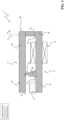
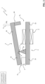
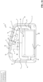
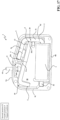
- the magnetic actuator 1 can be in a loaded condition ( figures 1 , 16 ), at which it is ready to provide a mechanical actuation force to an external mechanism, or in a tripped condition ( figures 2 , 17 ), at which it has already released a mechanical actuation force.
- the magnetic actuator 1 has a bistable behaviour and it can permanently stay in the above-mentioned loaded or tripped conditions.
- the magnetic actuator 1 can pass from a loaded condition to a tripped condition by carrying out a tripping manoeuvre upon receiving an electrical signal as an input.
- the magnetic actuator 1 can be restored from the above-mentioned tripped condition to the loaded condition through a loading manoeuvre carried out by a user or by an external loading mechanism.
- the magnetic actuator 1 comprises a magnetic circuit 10 including a fixed magnetic armature 2 rigidly coupled to a fixed support (e.g., the housing of the magnetic actuator) and a movable magnetic armature 3 operatively coupled to said fixed armature.
- the movable magnetic armature 3 can move relatively to the fixed magnetic armature 2. According to most of the embodiments shown in the cited figures, the movable magnetic armature 3 can move relatively to the fixed magnetic armature 2 by rotating about a rotation axis A.
- the movable magnetic armature 3 can move relatively to the fixed magnetic armature 2 by carrying out a roto-translation movement.
- the movable magnetic armature carries out a movement, which is the combination of a rotation movement (about a rotation axis) and translation movement relative to the fixed magnetic armature 2.
- a motion is typically defined as “rolling motion”, but it is not limited to a rolling motion in a strict sense.
- the movable magnetic armature can move relatively to the fixed magnetic armature by carrying out a translation movement.
- the present invention will be described with reference to the embodiments, in which the movable armature 3 is rotationally movable about a rotation axis.
- the movable magnetic armature 3 can move between a first position C and a second position O relative to the fixed magnetic armature 2.
- the first position C of the movable magnetic armature 3 corresponds to the loaded condition of the magnetic actuator while the second position O of the movable magnetic armature 3 corresponds to the tripped condition of the magnetic actuator.
- a transition of the movable magnetic armature 3 from the first position C to the second position O is part of a tripping manoeuvre of the magnetic actuator, during which said magnetic actuator provides a mechanical actuation force to an external mechanism, whereas a transition of the movable magnetic armature 3 from the second position O to the first position C is part of a loading manoeuvre of the magnetic actuator, during which said magnetic actuator is subjected to a mechanical actuation force by a user or an external loading mechanism.
- the magnetic armatures 2, 3 are formed by shaped pieces of ferromagnetic material (e.g., a nickel-iron alloy or the like).
- the magnetic armatures 2, 3 have an elongated shape and are juxtaposed one to another in such a way to have mutually facing surfaces.
- the rotation axis A of the movable magnetic armature 3 is perpendicular to the thickness and the longer dimension of the juxtaposed magnetic armatures (reference is made to the observation plane of figures 1-2 ).
- the magnetic circuit 10 further comprises a permanent magnet 4 configured to feed the fixed and movable magnetic armatures 2, 3 with a first magnetic flux ⁇ 1 having a predefined direction, when said permanent magnet is in a magnetized condition.
- the permanent magnet 4 is fixed (e.g., glued, spot-welded, or soldered) to the fixed magnetic armature 2.
- the permanent magnet 4 may be fixed to the movable magnetic armature 3 or even be fixed to a suitable support different from the magnetic armatures.
- the permanent magnet 4 may be formed by a monolithic structure of magnetic material (for example ferrite, AlNiCo or NdFeB) or by a plurality of elements of magnetic material, advantageously stacked one on another.
- magnetic material for example ferrite, AlNiCo or NdFeB
- the permanent magnet 4 is supposed to have the magnetic polarization shown in figures 1-6 , i.e., with the N pole and S pole oriented in such a way to generate a first magnetic flux ⁇ 1 having a predefined clockwise direction ( figures 3-6 ).
- the permanent magnet 4 may have an opposite magnetic polarization and generate a magnetic flux having an opposite direction.
- the permanent magnet 4 can be already in a magnetized condition when the magnetic actuator is assembled.
- the magnetic actuator 1 further comprises an excitation coil 5 operatively coupled to the magnetic circuit 10 in such a way to generate a magnetic flux in this latter, when fed with an electric current.
- the excitation coil 5 is fed with an electric current having a predetermined direction, when the magnetic actuator is in a loaded condition (first position C of the movable armature) and a tripping manoeuvre of the magnetic actuator must be carried out.
- the excitation coil 5 comprises one or more electrical windings electrically connected one to another and wound around one or more corresponding portions of the magnetic circuit 10. In this way, when an electric current circulates along it, the excitation coil 5 can generate a second magnetic flux ⁇ 2 having a predetermined direction and circulating along the fixed and movable magnetic armatures 2, 3.
- the excitation coil 5 may include one or more support structures (not shown) made of electrically insulating material, which are conveniently mounted on corresponding portions of magnetic circuit to support the above-mentioned one or more electrical windings.
- the excitation coil 5 has a single electrical winding arranged on a suitable support structure coupled to a corresponding portion of the magnetic circuit 10.
- the excitation coil 5 may have multiple windings electrically connected one to another and coupled to corresponding portions of the magnetic circuit 10.
- This last solution may be advantageously adopted when the magnetic actuator is required to have a particularly compact structure, particularly along a vertical dimension (perpendicular to the magnetic armatures 2, 3 in figures 1-2 ).
- the excitation coil 5 comprises also suitable power supply terminals (not shown) electrically connected to the above-mentioned one or more electrical windings to allow the excitation coil to be fed with an electric current having a predetermined direction.
- the excitation coil 5 thus generates a magnetic flux ⁇ 2 having a predefined direction, even when it includes multiple electric windings.
- the magnetic actuator 1 comprises also a movable plunger 6 mechanically coupled to the movable magnetic armature 3 in such a way to be actuated by this latter during a tripping manoeuvre of the magnetic actuator.
- the plunger 6 can reversibly move along a translation axis (preferably perpendicular to the fixed magnetic armature 2) between a third position E ( figure 1 ) and a fourth position F ( figure 2 ).
- the movable plunger 6 is in the third position E, when the movable magnetic armature 3 is in the first position C, while it is in the fourth position F, when the movable magnetic armature 3 is in the second position O.
- the plunger 6 translationally moves from the third position E to the fourth position F (first translation direction D 3 - figure 1 ) upon actuation by the movable magnetic armature 3, when this latter moves from the first position C to the second position O.
- the plunger 6 can provide an actuation force to an external mechanism.
- the plunger 6 translationally moves from the fourth position F to the third position E (second translation direction D 4 - figure 2 ), upon actuation by a user or an external loading mechanism. In doing so, the plunger 6 actuates the movable magnetic armature 3, which is consequently forced to move from the second position O to the first position C (loading manoeuvre).
- the movable plunger 6 moves along a translation directory perpendicular to the movable magnetic armature 3, when this latter is in the first position C.
- the magnetic actuator such as the permanent magnet 4, the excitation coil 5 and the movable plunger 6 may be realized according to solutions of known type. For this reason, these parts of the magnetic actuator will be described hereinafter only with reference to the aspects of interest of the invention, for the sake of brevity.
- the magnetic circuit 10 of the magnetic actuator is arranged according to an innovative configuration, which allows designing the magnetic actuator 1 with a simplified structure compared to traditional solutions of the state of the art. At the same time, the magnetic circuit 10 ensures a performant and reliable operation of the magnetic actuator without the need of additional actuating arrangements, such as springs or the like.
- the magnetic circuit 10 includes three branches 10a, 10b, 10c arranged in parallel one to another from an equivalent magnetic circuit point of view.
- the magnetic circuit 10 comprises a first branch 10a including a first portion 21 of fixed magnetic armature, a second portion 31 of fixed magnetic armature, the permanent magnet 4 and a first airgap region G 1 , which is arranged between the fixed magnetic armature 2 and the movable magnetic armature 3.
- airgap region generally identifies a region of the magnetic circuit 10, in which an airgap may be formed between two separable parts of said magnetic circuit, which are juxtaposed one to another.
- volume and shape of an airgap region generally change with the motion of a part (the movable magnetic armature) relative to the other (the fixed magnetic armature).
- the permanent magnet 4 is arranged between the fixed magnetic armature 2 and the movable magnetic armature 3.
- the permanent magnet 4 is advantageously fixed to the first portion 21 of fixed magnetic armature.
- the first airgap region G 1 is preferably formed between the permanent magnet 4 and the first portion 31 of movable magnetic armature 3.
- the permanent magnet 4 may be fixed to the movable magnetic armature.
- the first airgap region G 1 is preferably formed between the permanent magnet 4 and the first portion 21 of the fixed magnetic armature.
- a first portion 21 or 31 of fixed or movable magnetic armature may be formed by a shaped part or simply a region of the corresponding armature.
- the fixed magnetic armature 2 comprises a first portion 21 formed by a part of fixed armature having an elongated shape.
- the movable magnetic armature 3 includes a first portion 31 formed by a part of movable armature having an elongated shape.
- the first portion 31 of movable magnetic armature has not an elongated shaped but it is formed by a coupling region of the movable magnetic armature, which basically has the equivalent function of receiving the magnetic flux generated by the permanent magnet 4.
- the magnetic circuit 10 comprises a second branch 10b including a second portion 22 of the fixed magnetic armature, a second portion 32 of the movable magnetic armature 3 and a second airgap region G 2 between the fixed magnetic armature 2 and the movable magnetic armature 3.
- the second airgap region G 2 is formed between the second portion 22 of the fixed magnetic armature and the second portion 32 of the movable magnetic armature.
- a second portion 22 or 32 of fixed or movable magnetic armature may be formed by a shaped part or simply by a region of the corresponding armature.
- both the fixed magnetic armature 2 and movable magnetic armature 3 comprise a first portion 21 or 31 formed by parts of armature with an elongated shape.
- the magnetic circuit 10 comprises a third branch 10c including at least a magnetic shunt region G 3 between the fixed magnetic armature 2 and the movable magnetic armature 3.
- the magnetic shunt region G 3 is formed by an airgap region between adjacent parts of the fixed and movable magnetic armatures.
- the third branch 10c includes only the magnetic shunt region G 3 formed by a third airgap region between the fixed and movable magnetic armatures.
- the third branch 10c includes a third portion 23 of the fixed magnetic armature 2, which has a free end 23a facing the movable magnetic armature 3, and a magnetic shunt region G 3 formed by a third airgap region between this third portion 23 of the fixed magnetic armature and the movable magnetic armature 3.
- the third branch 10c includes a third portion 33 of the movable magnetic armature 3, which has a free end 33a facing the fixed magnetic armature.
- the third airgap region G 3 is formed between such a third portion of the movable magnetic armature and the fixed magnetic armature 2.
- the third branch 10c may include a third portion of the fixed magnetic armature 2 and a third portion of the movable magnetic armature 3.
- the magnetic shunt region G 3 is formed by a third airgap region is formed between these portions of the fixed and movable magnetic armatures.
- the above-mentioned first, second and third branches 10a, 10b, 10c define a pair of magnetic loops L 1 , L 2 of the magnetic circuit.
- a first magnetic loop L 1 is formed by the first and third branches 10a, 10c of the magnetic circuit while a second magnetic loop L 2 is formed by the second and third branches 10b, 10c.
- the magnetic loops L 1 , L 2 have thus the third branch 10c in common, which is apparently configured to form a magnetic shunt between the fixed magnetic armature 2 and the movable magnetic armature 3.
- Such a magnetic shunt is important to allow a portion ⁇ 12 of the first magnetic flux ⁇ 1 generated by the permanent magnet 4 to divert from a magnetic loop to another (e.g., from the second branch 10b to the third branch 10c) depending on the position of the movable armature 3 relative to the fixed magnetic armature.
- a magnetic shunt allows a portion ⁇ 12 of the first magnetic flux ⁇ 1 to divert from the second branch 10b to the third branch 10c, when the movable armature 3 moves away from the first position C towards the second position O.
- the first and second magnetic loops L 1 , L 2 are asymmetrically arranged, i.e., they define (closed) paths having different lengths for corresponding circulating magnetic fluxes.
- the second magnetic loop L 2 defines a longer path than the path defined by the first magnetic loop L 1 for a corresponding circulating magnetic flux.
- An important feature of the invention consists in that the first and second airgap regions G 1 , G 2 differ one from another for at least one of the following factors:
- first and second airgap regions G 1 , G 2 are arranged asymmetrically one from another. As an example, they are arranged in an asymmetric position relative to the magnetic shunt region G 3 .
- the magnetic shunt region G 3 is arranged at a shorter distance from the first airgap region G 1 and at a longer distance from the second airgap region G 2 (reference is made to the magnetic flux paths defined by the first and second magnetic loops L 1 , L 2 ).
- the rotation axis A of the movable magnetic armature 3 is located at juxtaposed coupling portions of the fixed magnetic armature 2 and the movable magnetic armature 3.
- the rotation axis A is located at the third airgap region G 3 .
- the rotation axis A is located between a free end 23a of the third portion 23 of the fixed magnetic armature and the movable magnetic armature 3.
- the rotation axis A is located at the free end 33a of the third portion 33 of the movable magnetic armature.
- the magnetic circuit 10 is configured so that the rotation axis A of the movable magnetic armature 3 is located in an asymmetric position between the first and second airgap regions G 1 , G 2 .
- the rotation axis A of the movable magnetic armature 3 is preferably located at different distances from the first and second airgap regions G 1 , G 2 . More particularly, the rotation axis A is located at a shorter distance from the first airgap region G 1 and at a longer distance from the second airgap region G 2 (reference is made to the magnetic flux paths defined by the first and second magnetic loops L 1 , L 2 ).
- the excitation coil 5 is operatively coupled to the magnetic circuit 10 in such a way to feed the second and third branches 10b, 10c of the magnetic circuit with a second magnetic flux ⁇ 2 having, at least along the second branch 10b of the magnetic circuit, an opposite direction compared to the first magnetic flux ⁇ 1 generated by the permanent magnet 4, when said excitation coil is fed with an electric current.
- the excitation coil 5 is advantageously coupled to the second portion 22 of the fixed magnetic armature.
- the excitation coil 5 may be located at any position along the second and third branches 10b, 10c of the magnetic circuit 10, for example at the second portion 32 of the movable magnetic armature or at the above-mentioned third portion of the fixed magnetic armature.
- the excitation coil 5 has preferably a single electrical winding.
- the excitation coil 5 may have multiple windings electrically connected one to another (e.g. in series) and located at corresponding positions along the second and third branches 10b, 10c of the magnetic circuit 10.
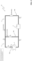
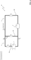
- Figures 3-6 show a magnetic circuit having a structure equivalent to the magnetic circuit 10. As it is possible to notice, the branches 10a, 10b, 10c are arranged in parallel.
- Each branch 10a, 10b, 10c has a corresponding magnetic reluctance R 1 , R 2 , R 3 .
- the magnetic reluctances values R 1 , R 2 , R 3 of the first, second and third branches 10a, 10b, 10c of the magnetic circuit 10 are mutually interrelated and variable depending on the position of the movable magnetic armature 3 relative to the fixed magnetic armature 2.
- the magnetic circuit 10 is configured so that the first and second branches 10a, 10b have magnetic reluctances R 1 , R 2 varying in opposite ways one from another, as a function of the position of the movable magnetic armature 3.
- the magnetic circuit 10 is configured so that, when the movable magnetic armature 3 moves away from the first position C towards the second position O, the first branch 10a of the magnetic circuit 10 has a first magnetic reluctance R 1 decreasing with the movement of the movable magnetic armature 3 while the second branch 10b of the magnetic circuit 10 has a second magnetic reluctance R 2 increasing with the movement of the movable magnetic armature 3.
- the second branch 10b has a second magnetic reluctances R 2 varying more quickly than the magnetic reluctance R 1 of the first branch 10a in response to a movement of the movable magnetic armature.
- the second magnetic reluctance R 2 has, in modulus, a rate of change higher than the rate of change (derivative over a dimensional parameter) of the first magnetic reluctance R 1 in response to a movement of the movable magnetic armature 3.
- the above-illustrated concept may be summarized by the following relation: ⁇ R 2 ⁇ p R 3 2 R 2 + R 3 2 > ⁇ R 1 ⁇ p
- R 1 , R 2 , R 3 are the above-mentioned first, second and third magnetic reluctances and p is a mono-dimensional parameter describing the movement of the movable magnetic armature.
- p ⁇ is the angular distance of the movable magnetic armature relative to the fixed magnetic armature magnetic armature.
- the above-mentioned mono-dimensional parameter p may be a relative linear distance from the fixed magnetic armature magnetic armature when the movable magnetic armature moves translationally.
- the second magnetic reluctance R 2 has, in modulus, a rate of change much higher (for example at least twice higher) than the rate of change of the first magnetic reluctance R 1 in response to a movement of the movable magnetic armature 3.
- the first and second magnetic reluctances R 1 , R 2 vary according to the following relation: ⁇ R 2 ⁇ p ⁇ ⁇ R 1 ⁇ p where R 1 , R 2 are the above-mentioned first and second magnetic reluctances and p is the above-mentioned mono-dimensional parameter describing the movement of the movable magnetic armature.
- the magnetic circuit 10 is configured so that the second and third branches 10b, 10c have magnetic reluctances R 2 , R 3 varying in different ways as a function of the position of the movable magnetic armature 3.
- the magnetic circuit 10 is configured so that, when the movable magnetic armature 3 moves away from the first position C towards the second position O, the second branch 10b of the magnetic circuit 10 has a second magnetic reluctance R 2 becoming much higher than the third magnetic reluctance R 3 of the third branch 10c of the magnetic circuit 10.
- the magnetic circuit 10 is configured so that the ratio between the second magnetic reluctance R 2 and the third magnetic reluctance R 3 increases, when the movable magnetic armature 3 moves from the first position C to the second position O.
- the above-illustrated behaviour of the first, second and third magnetic reluctances R 1 , R 2 , R 3 of the first, second and third branches 10a, 10b, 10c of the magnetic circuit apparently depends on the above-illustrated asymmetric arrangement of the first and second magnetic loops L 1 , L 2 .
- the movable magnetic armature 3 of the magnetic circuit 10 is actuated by exploiting the sole magnetic energy stored by the magnetic loops L 1 , L 2 without the use of additional mechanical means (e.g., actuation springs), as it occurs in traditional solutions of the state of the art.
- additional mechanical means e.g., actuation springs
- the permanent magnet 4 and the magnetic material used in the magnetic circuit 10 are supposed to have an ideal behaviour
- the magnetic flux ⁇ 1 and the electric current Ic are supposed to be independent from the position of the movable magnetic armature
- the magnetic reluctances R 1 , R 2 of the first and second branches 10, 10b are supposed to vary linearly with the position of the movable magnetic armature while the magnetic reluctances R 3 of the third branch 10c is supposed to be constant.
- the magnetic reluctances values R 1 , R 2 of the first and second branches 10a, 10b of the magnetic circuit 10 vary with the position of the movable magnetic armature 3 relative to the fixed magnetic armature 2.
- the stored magnetic energy E is thus variable depending on the position of the movable magnetic armature 3 relative to the fixed magnetic armature.
- the stored magnetic energy E is mostly due the first magnetic flux ⁇ 1 generated by the permanent magnet. Obviously, the magnetic energy E depends also on the second magnetic flux ⁇ 2 generated by the excitation coil 5, when this latter is fed with an electric current I C (see the addendum describing the magnetic energy E L2 stored by the second magnetic loop L 2 ).
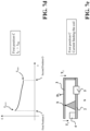
- Figure 7 schematically shows a 3D graph showing the behaviour the magnetic energy E (the indicated values are shown for illustrative purposes only) as a function of the electric current I C feeding the excitation coil 5 and of a mono-dimensional parameter describing the movement of the movable magnetic armature.
- the magnetic energy E takes a first relative minimum value Ei, when the movable magnetic armature 3 is in the first position C, a second relative minimum value E 2 , when the movable magnetic armature 3 is in the second position O, and an absolute maximum value E MAX when the movable magnetic armature 3 takes an intermediate position between the first position C and the second position O (see also figure 7b ).
- the maximum value E MAX taken by the stored magnetic energy E increases and shifts towards positions of the movable magnetic armature progressively closer to the first position C (see the dotted arrow crossing the energy curves in the graph of figure 7 ).
- the magnetic energy E takes an absolute maximum value E MAX at a position of the movable magnetic armature corresponding to the first position C.
- the magnetic energy E decreases monotonically for positions of the movable magnetic armature progressively closer to the second position O and takes an absolute maximum value E MIN at a position of the movable magnetic armature corresponding to the second position O (see also figure 7d ).
- the magnetic energy E stored by the magnetic circuit 10 behaves quite similarly in the embodiments of the invention, in which the movable magnetic armature 3 moves roto-translationally or translationally relative to the fixed magnetic armature 2.
- a mono-dimensional parameter different from the relative angular distance ⁇ may be conveniently selected to describe the position of the movable magnetic armature 3 relative to the fixed magnetic armature 2.
- the movable magnetic armature 3 is subjected to magnetic forces generated by the magnetic fluxes circulating along the first and second magnetic loops L 1 , L 2 .
- magnetic forces refers to torques actuating the movable magnetic armature if the movable magnetic armature moves rotationally, or to linear forces actuating the movable magnetic armature if the movable magnetic armature moves translationally, or to combinations of torques and linear forces actuating the movable magnetic armature, if the movable magnetic armature moves roto-translationally.
- I c const where I C is the electric current feeding the excitation coil 5, p is a mono-dimensional parameter describing the movement of the movable magnetic armature. In practice, the parameter p is descriptive of the relative position of the movable magnetic armature 3 relative to the fixed magnetic armature 2.
- the magnetic forces can be given by the following relation: ⁇ E ⁇ p
- ⁇ 1 is the magnetic flux generated by the permanent magnet 4
- I C is the electric current /feeding the excitation coil 5
- R 1 , R 2 , R 3 are the magnetic reluctances of the first, second and third branches 10a, 10b, 10c of the magnetic circuit, respectively
- p is a mono-dimensional parameter describing the movement of the movable magnetic armature.
- first and second branches 10a, 10b have magnetic reluctances R 1 , R 2 varying in opposite ways one from another, as a function of the position of the movable magnetic armature 3.
- Such a magnetic force is directed in such a way to move the movable magnetic armature from the first position C to the second position O.
- Such a magnetic force is directed in such a way to move the movable magnetic armature away from the second position O to the first position C.
- first and second magnetic forces F 1 , F 2 actuating the movable magnetic armature are mutually interrelated and obviously depend on the position of the movable magnetic armature relative to the fixed magnetic armature.
- the above-mentioned first magnetic force F 1 increases and the above-mentioned second magnetic force F 2 decreases, when the movable magnetic armature 3 moves away from the first position C towards the second position O.
- the second magnetic force F 2 varies more quickly than the first magnetic force F1 in response to a movement of the movable magnetic armature, when said movable magnetic armature starts moving away from the first position C (in practice when the movable magnetic armature is moving but it has just left the first position C and it is still in proximity of this latter).
- the rate of change (derivative over a dimensional parameter) of the second magnetic force F 2 is, in modulus, higher than the rate of change of the first magnetic force F 1 in response to a movement of said movable magnetic armature, when said movable magnetic armature starts moving away from the first position C.
- the rate of change of the second magnetic force F 2 is, in modulus, much higher than the rate of change of the first magnetic force F 1 in response to a movement of said movable magnetic armature, when said movable magnetic armature starts moving away from the first position C.
- the first and second magnetic F 1 , F 2 vary according to the following relation: ⁇ F 2 ⁇ p ⁇ ⁇ F 1 ⁇ p where F 1 , F 2 are the above-mentioned opposite first and second magnetic forces and p is a mono-dimensional parameter describing the movement of the movable magnetic armature.
- the above-mentioned first magnetic force F 1 increases and the second magnetic force F 2 decreases as a highly non-linear function (for example as a hyperbolic function or as an exponential function with negative exponent) in response to a movement of said movable magnetic armature, when said movable magnetic armature starts moving away from the first position C.
- a highly non-linear function for example as a hyperbolic function or as an exponential function with negative exponent
- the movable magnetic armature in which the movable magnetic armature moves rotationally, the movable magnetic armature is subjected to opposite magnetic torques, which may be calculated according to the following relation: ⁇ E ⁇ ⁇
- ⁇ 1 is the magnetic flux generated by the permanent magnet 4
- I C is the electric current feeding the excitation coil 5
- R 1 , R 2 , R 3 are the magnetic reluctances of the first, second and third branches 10a, 10b, 10c of the magnetic circuit, respectively
- ⁇ is the angular distance of the movable magnetic armature relative to the fixed magnetic armature.
- a first magnetic torque T 1 ⁇ R 1 ⁇ ⁇ ⁇ 1 2 , which depends on the magnetic energy stored by the first magnetic loop L 1 , is directed in such a way to move the movable magnetic armature from the first position C to the second position O.
- a second magnetic torque T 2 ⁇ R 2 ⁇ ⁇ R 3 ⁇ 1 ⁇ I C 2 R 2 + R 3 2 , which is opposite to the first magnetic torque T 1 and depends on the magnetic energy stored by the second magnetic loop L 2 , is directed in such a way to move the movable magnetic armature away from the second position O to the first position C.
- first and second magnetic torques T 1 , T 2 actuating the movable magnetic armature are mutually interrelated and depend on the position of the movable magnetic armature relative to the fixed magnetic armature.
- the opposite first and second magnetic torques T 1 , T 2 behave as illustrated above in relation to the opposite first and second magnetic forces F 1 , F 2 , when the movable magnetic armature 3 moves away from the first position C towards the second position O, more particularly when said movable magnetic armature starts moving away from the first position C (in practice when the movable magnetic armature is moving but it has just left the first position C and it is still in proximity of this latter).
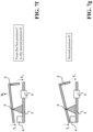
- Figure 7a schematically shows the behaviour of the opposite magnetic torques T 1 , T 2 exerted on the movable magnetic armature 3 as a function of the angular distance ⁇ of the movable magnetic armature relative to the fixed magnetic armature.
- the first magnetic torque T 1 exerted on the movable armature 3 increases with a movement of the movable magnetic armature from the first position C to the second position O.
- the first magnetic torque T 1 increases very slowly, approximately as a linear function in response to a movement of the movable magnetic armature, when the movable magnetic armature starts moving away from the first position C.
- the second magnetic torque T 2 exerted on the movable armature 3 decreases with a movement of the movable magnetic armature from the first position C to the second position O.
- the second magnetic torque T 2 decreases very quicky, approximately as a highly non-linear function (for example as a hyperbolic function or as an exponential function with negative exponent) in response to a movement of the movable magnetic armature, when this latter starts moving away from the first position C.
- a highly non-linear function for example as a hyperbolic function or as an exponential function with negative exponent
- the second magnetic torque T 2 is higher than the first magnetic torque T 1 .
- the second magnetic torque T 2 decreases very quickly as soon as the movable magnetic armature starts moving away from the first position C.
- the first magnetic torque T 1 overcomes the second magnetic torque T 2 at the transition point P. Beyond the transition point P, the first magnetic torque T 1 remains higher than the second magnetic torque T 2 as the first magnetic torque T 1 continues to increase and second magnetic torque T 2 continues to decrease.
- the magnetic actuator is initially supposed to be in a loaded condition with the excitation coil 5 not fed by an electric current ( figures 1 , 3 , 7b-7c ).
- the movable magnetic armature 3 is the first position C corresponding to the loaded condition of the magnetic actuator.
- the first magnetic flux ⁇ 1 generated by the permanent magnet 4 flows according to a predefined direction (clockwise direction in figures 3-6 ) along the parallel branches 10a, 10b, 10c of the magnetic circuit.
- the first magnetic flux ⁇ 1 generated by the permanent magnet 4 flows along the first branch 10a and splits into two components ⁇ 12 , ⁇ 13 flowing along the second and third branches 10b, 10c according to the magnetic reluctances R 2 , R 3 of these last branches of the magnetic circuit.
- the magnetic energy E stored by the first and second magnetic loops L 1 , L 2 takes a first relative minimum value E 1 ( figure 7b ).
- the movable magnetic armature therefore cannot move from the first position C.
- the first magnetic force F 1 which is directed in such a way to move the movable magnetic armature away from the first position C, is lower than the second magnetic force F 2 , which is directed in such a way to move the movable magnetic armature towards said first position C. Consequently, the movable magnetic armature 3 can permanently stay in the first position C ( figure 7c ).
- the movable magnetic armature 3 is rotatably movable about the rotation axis A
- the movable magnetic armature 3 is subjected to opposite first and second magnetic torques T 1 , T 2 ( figure 7c ).
- the first magnetic torque T 1 is directed to move the movable magnetic armature away from the first position C while the second magnetic torque T 2 is directed to hold the movable magnetic armature in the first position C.
- the movable magnetic armature 3 is in the first position C and the excitation coil 5 is fed with an electric current higher than a threshold value I TH to start the tripping manoeuvre ( figures 1 , 4 , 7c-7d ).
- the excitation coil 5 generates a second magnetic flux ⁇ 2 circulating along the second branch 10b of the magnetic circuit and having an an opposite direction compared to the first magnetic flux ⁇ 12 generated by the permanent magnet 4 ( figure 4 ).
- the second magnetic flux ⁇ 2 splits into two components ⁇ 21 , ⁇ 23 flowing along the first and third branches 10a, 10c according to the magnetic reluctances R 1 , R 3 of these last branches of the magnetic circuit ( figure 4 ).
- the component ⁇ 21 of the second magnetic flux is very low and can be neglected ( ⁇ 2 ⁇ ⁇ 23 ), which means that almost all the second magnetic flux ⁇ 2 circulates along the second magnetic loop L 2 .
- the magnetic energy E stored by the first and second magnetic loops L 1 , L 2 takes an absolute maximum value E MAX ( figure 7d ).
- the movable magnetic armature 3 is thus forced to move towards a position with lower energy, in practice to move away from the first position C towards the second position O.
- the second magnetic force F 2 which is directed in such a way to hold the movable magnetic armature away from the first position C, decreases as the second magnetic flux ⁇ 2 generated by the excitation coil 5 opposes, along the second branch 10b of the magnetic circuit, the magnetic flux ⁇ 12 generated by the permanent magnet 4.
- the second magnetic force F 2 thus becomes lower that the first magnetic force F 1 , which is directed in such a way to move said movable magnetic armature away from the first position C.
- the movable magnetic armature 3 is rotatably movable about the rotation axis A
- the movable magnetic armature is still subject to opposite first and second magnetic torques T 1 , T 2 ( figure 7e ).
- the second magnetic torque T 2 which is exerted on the movable magnetic armature and directed in such a way to hold the movable magnetic armature in the first position C, decreases and becomes lower than the first magnetic torque T 1 exerted on the movable magnetic armature and directed in such a way to move the movable magnetic armature away from the first position C.
- the excitation coil 5 is aimed at providing a magnetic flux ⁇ 2 directed in such a way to allow the magnetic movable armature 3 to move over a position of maximum energy ⁇ E ( figure 7b ) so that it can naturally move towards another position, in which the stored magnetic energy takes a relative minimum value E 2 .
- the excitation coil 5 is apparently aimed at providing a magnetic flux ⁇ 2 directed in such a way to allow the magnetic movable armature 3 to reach a transition point P despite of the counteraction of the second magnetic torque T 2 , which is initially higher than the first magnetic torque T 1 ( figure 7a ).
- the excitation coil 5 does not need to be fed anymore.
- the sole magnetic energy provided by the permanent magnet 4 is exploited to actuate the movable magnetic armature 3.
- the second branch 10b of the magnetic circuit has a magnetic reluctance R 2 that becomes higher than the magnetic reluctance R 3 of the third branch 10c.
- the magnetic flux generated by the first permanent magnet 4 progressively divert from the second branch 10b towards the third branch 10c of the magnetic circuit.
- the component ⁇ 12 of the first magnetic flux ⁇ 1 which flows along the second branch 10b of the magnetic circuit, progressively decreases while the component ⁇ 13 of the first magnetic flux ⁇ 1 , which flows along the third branch 10c of the magnetic circuit, progressively increases.
- the magnetic energy E stored by the magnetic circuit progressively decreases with the movement of the movement of the movable magnetic armature until it takes a second relative minimum for a position of the movable magnetic armature corresponding to the second position E 2 .
- the movable magnetic armature is thus forced to move towards the second position O, at which the stored takes a minimum value E 2 .
- the second magnetic force F 2 which is directed in such a way to hold the movable magnetic armature away from the first position C, remains lower that the first magnetic force F 1 , which is directed in such a way to move said movable magnetic armature away from the first position C, even if the excitation coil 5 is no more fed with an electric current.
- the movable magnetic armature 3 is rotatably movable about the rotation axis A
- the movable magnetic armature is still subject to opposite first and second magnetic torques T 1 , T 2 ( figure 7f ).
- the magnetic movable armature 3 has now overcome the transition point P of figure 7a and the second magnetic torque T 2 becomes lower that the first magnetic torque T 1 .
- the second magnetic torque T 2 quickly decreases with the movement of the movable magnetic armature since the magnetic flux circulating along the second magnetic loop L 2 of the magnetic circuit diverts towards the first magnetic loop L 1 .
- the second magnetic torque T 2 remains lower than the first magnetic torque T 1 and the movable magnetic armature 3 continues to move away from the first position C until it reaches the second position O (rotation direction D 1 - figure 7f ).
- the excitation coil 5 is activated only for starting the movement of the movable magnetic armature 3 away from the first position C. As soon as the movement of the movable magnetic armature 3 starts, the sole magnetic energy provided by the permanent magnet 4 is exploited to complete the movement of the movable magnetic armature 3 towards the second position O without the need of mechanical means such as preloaded springs or the like.
- the movable magnetic armature 3 is in the second position O.
- the first magnetic flux ⁇ 12 along the second branch 10b of the magnetic circuit is virtually null since the magnetic reluctance R 2 of the second branch 10b is much higher than the magnetic reluctance R 3 of the third branch 10c ( figure 6 ).
- the whole first magnetic flux ⁇ 1 generated by the permanent magnet 4 circulates along the first magnetic loop L 1 of the magnetic circuit ( ⁇ 1 ⁇ ⁇ 12 ).
- the magnetic energy E stored by the first and second magnetic loops L 1 , L 2 takes a second relative minimum value E 2 ( figure 7b ).
- the movable magnetic armature 3 therefore cannot move from the second position O.
- the first magnetic force F 1 which is directed in such a way to move said movable magnetic armature away from the first position C, is higher than the second magnetic force F 2 , which is directed in such a way to move the movable magnetic armature towards said first position C.
- the movable magnetic armature 3 is rotatably movable about the rotation axis A
- the movable magnetic armature 3 is still subject to opposite first and second magnetic torques T 1 , T 2 ( figure 7g ).
- the second magnetic torque T 2 is substantially lower (virtually null) than the first magnetic torque T 1 . Consequently, the movable magnetic armature 3 is hold permanently in the second position O (tripped condition of the magnetic actuator).
- the movable magnetic armature is in the second position O and the excitation coil 5 is not fed.
- a user or an external mechanism In order to restore a loaded condition of the magnetic actuator, a user or an external mechanism must exert an external actuation force on the movable magnetic armature.
- the user or an external mechanism provides the energy necessary for bringing the magnetic energy E stored by the first and second magnetic loops L 1 , L 2 from the second relative minimum value E 2 to the first relative minimum value E 1 ( figure 7b ).
- the external actuation force can be exerted only for the time necessary for bringing the movable magnetic armature 3 in proximity of the first position C.
- the movable magnetic armature 3 will be subject to an overall magnetic force directed in such a way to move it towards the first position C.
- a user or an external mechanism must exert an external actuation torque T E ( figure 7h ), which is directed to move the movable magnetic armature 3 away from the second position O and towards the first position C.
- the applied external actuation torque T E must overcome the opposite magnetic torque T 1 generated by the first magnetic flux ⁇ 1 provided by the permanent magnet 4) and directed in such a way to hold the movable magnetic armature in the second position O.
- the movable magnetic armature is thus moved towards the first position C (second rotation direction D 2 - figure 7h ).
- the movable magnetic armature 3 When it reaches the first position C, the movable magnetic armature 3 permanently stays in the first position C (loaded condition of the magnetic actuator) for the reasons explained above.
- the magnetic circuit 10 can be fit in several relevant configurations, some of which are described in the following with particular reference to figures 8 -18. In all these embodiments, the magnetic circuit 10 operates substantially as described above.
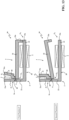
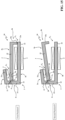
- Figure 8 shows a first configuration of the magnetic circuit 10.
- the magnetic circuit 10 has a fixed magnetic armature 2 with substantially a rectilinear geometry.
- the fixed magnetic armature 2 includes a first elongated portion 21 and a second elongated portion 22, which are mutually co-planar, and a third portion 23 protruding perpendicularly relative to the extension plane of the first and second portions 21, 22.
- the first and second portions 21, 22 of the fixed magnetic armature have both a rectilinear shape with opposite free ends 21a, 22a.
- the third portion 23 of the fixed magnetic armature is formed at a joining region 20 between the first and second portions 21, 22 and it includes a free end 23a with a flat terminal surface.
- the permanent magnet 4 is fixed to the first portion 21 of the fixed magnetic armature, preferably in proximity of the corresponding free end 21a, while the excitation coil 5 is wound on the second portion 22 of the fixed magnetic armature.
- the magnetic circuit 10 has movable magnetic armature 3 juxtaposed to the fixed magnetic armature 2 and with substantially a rectilinear geometry and opposite free ends 31a, 32a.
- the movable magnetic armature 3 is coupled to the third portion 23 of the fixed magnetic armature and it is free to move about a rotation axis A, which is thus located the free end 23a and the movable magnetic armature 3.
- the movable magnetic armature 3 comprises a first elongated portion 31 and a second elongated portion 32 extending along planes intersecting at the rotation axis A and preferably forming an obtuse angle.
- the first and second portions 31, 32 of the movable magnetic armature join at a joining region 30, at which the movable magnetic armature 3 is coupled to the free end 23a of the third portion 23 of the fixed magnetic armature.
- the joining region 30 of the movable magnetic armature has a V-shaped profile in such a way to favor the rotating movements of the movable magnetic armature.
- the first portion 31 of the movable magnetic armature has a rectilinear shape with a corresponding free end 31a facing the permanent magnet 4.
- the second portion 32 of the movable magnetic armature has a reversed L-shape with a longer leg facing the second portion 22 of the fixed magnetic armature and a shorter leg directed towards the second portion 22 with a corresponding free end 32a facing the free end 22a of the fixed magnetic armature.
- the magnetic circuit 10 has a first airgap region G 1 formed between the free end 31a of the movable magnetic armature and the permanent magnet 4, a second airgap region G 2 formed between the free end 32a of the movable magnetic armature and the free end 22a of the fixed magnetic armature and a third airgap region G 3 formed between the V-shaped region 30 of the movable magnetic armature 3 and the free end 23a of the third portion 23 of the fixed magnetic armature.
- the magnetic circuit 10 has an equivalent magnetic structure including three branches arranged in parallel, namely a first branch ( figures 3-6 , reference 10a) including the first portion 21 of the fixed magnetic armature, the permanent magnet 4, the first airgap region G 1 and the first portion 31 of the movable magnetic armature, a second branch ( figures 3-6 , reference10b) including the second portion 22 of the fixed magnetic armature, the second airgap region G 2 and the second portion 32 of the movable magnetic armature and a third branch ( figures 3-6 , reference 10c) including the third portion 23 of the fixed magnetic armature and the third airgap region G 3 .
- the magnetic circuit defines two magnetic loops having asymmetrical configurations.
- the third airgap region G 3 is arranged in an asymmetric position relative to the first and second airgap regions G 1 , G 2 .
- the rotation axis A of the movable magnetic armature 3 is located in proximity of the third airgap region G 3 .
- the magnetic circuit 10 configured according to the solution shown in figure 8 has a particularly simple and robust structure, which is quite easily to realize at industrial level. Additionally, it allows building a magnetic actuator with a particularly compact size according to a direction perpendicular to the movable magnetic armature 3 (vertical direction), when this latter is in the first position C.
- the free end 23a of the third portion 23 of the fixed magnetic armature may be covered with a soft magnetic material (for example an elastomer having magnetic properties).
- a soft magnetic material for example an elastomer having magnetic properties.
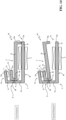
- Figure 9 shows another configuration of the magnetic circuit 10.
- the magnetic circuit 10 is configured very similarly to the embodiment shown in figure 8 .
- the features in common with this embodiment 8 will be not described in detail for the sake of brevity.
- the free end 23a of the third portion 23 of the fixed magnetic armature has a V-shaped surface having a profile complementary to the profile of the V-shaped joining region 30 of the movable magnetic armature 3, at which the movable magnetic armature 3 is rotatably coupled to the free end 23a of the fixed magnetic armature.
- the first portion 21 of the fixed magnetic armature has a L-shape with the shorter leg including the free end 21a.
- the shorter leg of the first portion 21 has an enlarged section while the free end 21a has an oblique terminal surface, on top of which the permanent magnet 4 is fixed.
- This embodiment of the invention offers remarkable advantages in terms of stabilization of the rotation movements of the movable magnetic armature 3, which allows reducing undesired vibrations influencing the movements of the movable magnetic armature.
- Figure 10 shows a further configuration of the magnetic circuit 10, which is similar to the configurations of figures 8-9 in many respects.
- the features in common with these embodiments will be not described in detail for the sake of brevity.
- the first and second portions 21, 22 of the fixed magnetic armature extend along intersecting planes, preferably with an angle greater than 180°.
- the first portion 21 of the fixed magnetic armature has a rectilinear shape with a free end 21a in proximity of which the permanent magnet 4 is fixed to the fixed magnetic armature.
- the second portion 22 of the fixed magnetic armature has a L-shape with a shorter leg directed towards the movable magnetic armature 3 and including a corresponding free end 22a facing the movable magnetic armature.
- the third portion 23 of the fixed magnetic armature has a free end 23a juxtaposed to movable magnetic armature and having a rounded profile.
- the first and second portions 31, 32 of the movable magnetic armature 3 have both a rectilinear shape and are co-planar.
- the first portion 31 of the movable magnetic armature has a free end 31a facing the permanent magnet 4 to form the first airgap region G 1 while the second portion 32 has a free end 32a facing the free end 22a of the fixed magnetic armature to form the second airgap region G 2 .
- the free end 31a of the movable magnetic armature is adjacent to the free end 21a of the fixed magnetic armature, while, when the movable armature is in the first position C, the free end 32a of the movable magnetic armature is adjacent to the free end 22a of the fixed magnetic armature.
- the movable magnetic armature 3 is movable about a rotation axis A located at the free end 23a of the third portion 23 of the fixed magnetic armature. In operation, however, due to the rounded shape of the free end 23a, the movable magnetic armature 3 carries out a roto-translation when moving between the above-mentioned first and second positions.
- the movable magnetic armature 3 comprises a coupling surface at which the movable armature 3 is rotatably coupled the fixed magnetic armature.
- a coupling surface has conveniently a rounded profile, preferably with a curvature radius slightly larger than the curvature radius of the free end 23a of the third portion 23 of the fixed magnetic armature in such a way to allow a roto-translation movement of the movable magnetic armature 3 relative to the fixed magnetic armature 2.
- This embodiment of the invention is characterised by an improved coupling between the fixed and movable magnetic armatures, which provides further advantages in terms of stabilization of the rotation movements of the movable magnetic armature 3. Additionally, the size of the third airgap region G 3 substantially remains constant with the movement of the movable magnetic armature 3.
- Figure 11 shows a further configuration of the magnetic circuit 10.
- the magnetic circuit 10 has basically an overall structure symmetric compared to the embodiment shown in figure 10 .
- the fixed magnetic armature 2 includes a first elongated portion 21 and a second elongated portion 22 having rectilinear shape and mutually co-planar.
- the first and second portions 21, 22 of the fixed magnetic armature are joined at a joining region 20 and have opposite free ends 21a, 22a.
- the permanent magnet 4 is fixed to the first portion 21 of the fixed magnetic armature, preferably in proximity of the corresponding free end 21a, while the excitation coil 5 is coupled to the second portion 22 of the fixed magnetic armature.
- the movable magnetic armature 3 comprises a first elongated portion 31 and a second elongated portion 32 extending along planes intersecting at the rotation axis A and preferably forming an obtuse angle.
- the first portion 31 of the movable magnetic armature has a rectilinear shape with a corresponding free end 31a facing the permanent magnet 4 to form the first airgap region G 1 .
- the second portion 32 of the movable magnetic armature has a reversed L-shape with a longer leg facing the second portion 22 of the fixed magnetic armature and a shorter leg directed towards the second portion 22 with a corresponding free end 32a facing the free end 22a of the fixed magnetic armature to form the second airgap region G 2 .
- the free end 31a of the movable magnetic armature is adjacent to the free end 21a of the fixed magnetic armature, while, when the movable armature is in the first position C, the free end 32a of the movable magnetic armature is adjacent to the free end 22a of the fixed magnetic armature.
- the movable magnetic armature 3 comprises a third portion 33 protruding towards the first and second portions 21, 22 of the fixed magnetic armature 2 perpendicularly to these latter.
- the third portion 33 of the movable magnetic armature has a free end 33a facing the joining region 20 of the fixed magnetic armature 2 and having a rounded profile.
- the movable magnetic armature 3 is movable about a rotation axis A located at the free end 33a of the third portion 33 of the movable magnetic armature. In operation, however, due to the rounded shape of the free end 33a, the movable magnetic armature 3 carries out a roto-translation when moving between the above-mentioned first and second positions.
- the fixed magnetic armature 2 comprises a coupling surface at which the movable armature 3 is rotatably coupled to the fixed magnetic armature 2.
- a coupling surface has conveniently a rounded profile, preferably with a curvature radius slightly larger than the curvature radius of the free end 33a of the third portion 33 of the movable magnetic armature in such a way to allow a roto-translation movement of the movable magnetic armature 3 relative to the fixed magnetic armature 2.
- this embodiment of the invention is characterised by an improved coupling between the fixed and movable magnetic armatures.
- Figure 12 shows a further configuration of the magnetic circuit 10.
- the magnetic circuit 10 has basically an overall structure similar, for many aspects, to the embodiments shown in figures 8-9 .
- the features in common with these embodiments will be not described in detail for the sake of brevity.
- the first portion 21 of the fixed magnetic armature has a free end 21a having an anvil-like shape with an oblique terminal surface, on top of which the permanent magnet 4 is fixed.
- the first portion 31 of the movable magnetic armature 3 has an articulated shape with a first leg 311 and a second leg 312.
- the first leg 311 is joined to the second portion 31 of the movable magnetic armature 3 and it is angled relative to this latter.
- the second leg 312 is joined to the first leg 311 and it includes the free end 31a of the first portion 31 of the movable magnetic armature.
- the second leg 312 is oriented towards the fixed magnetic armature 2 and it is angled relative to the first leg 311 in such a way to be coupled with the permanent magnet 4 when the movable armature 3 is in the second position O.
- the first airgap region G 1 is formed between the second leg 312 of the movable magnetic armature and the permanent magnet 4.
- the magnetic reluctance of the first airgap region G 1 depends on the mutual distance between the second leg 312 of the movable magnetic armature and the permanent magnet 4 and on the area of the mutually facing surfaces of the second leg 312 and the permanent magnet 4.
- the above-mentioned parameters can be designed to obtain a first magnetic torque T 1 (directed in such a way to move the movable magnetic armature 3 away from the first position C) less dependent on the movements of the movable magnetic armature.
- Figure 13 shows another configuration of the magnetic circuit 10, which represents an evolution of the embodiments shown in figures 8-12 .
- the fixed magnetic armature 2 is formed by a first L-shaped structure having a shorter leg 2a and a longer leg 2b that are mutually perpendicular.
- the first portion 21 of the fixed magnetic armature includes part of the shorter leg 2a while the second portion 22 of the fixed magnetic armature includes the remaining part of the shorter leg 2a and the longer leg 2b.
- the first and second portions 21, 22 of the fixed magnetic armature are joined at a first joining region 20 (dotted line) and have opposite free ends 21a, 22a.
- the permanent magnet 4 is fixed to the first portion 21 of the fixed magnetic armature at the shorter leg 2a in proximity of the free end 21a while the excitation coil 5 is coupled to the second portion 22 of the fixed magnetic armature at the longer leg 2b.
- the movable magnetic armature 3 has an articulated structure configured in such a way to have a shape complementary to the shape of the assembly formed by the fixed magnetic armature 3 and the permanent magnet 4.
- the first portion 31 of the movable magnetic armature has a zig-zag shape and it is oriented in such a way to face the first portion 21 of the fixed magnetic armature.
- the first portion 31 of the movable magnetic armature includes a free end 31a facing the permanent magnet 4.
- the first portion 31 of the movable magnetic armature is mostly oriented in parallel to the second portion 21 of the fixed magnetic armature and the free end 31a of the movable magnetic armature is adjacent to the free end 21a of the fixed magnetic armature.
- the second portion 32 of the movable magnetic armature has a reversed-L shape.
- the second portion 32 of the movable magnetic armature is oriented in such a way to have a longer leg facing the second portion 22 of the fixed magnetic armature and a shorter leg including a free end 32a directed towards the second portion 22 of the fixed magnetic armature and facing the free end 22a of this latter.
- the free end 32a of the movable magnetic armature is adjacent to the free end 22a of the fixed magnetic armature, when the movable magnetic armature 3 is in the first position C.
- the first and second portions 31, 32 of the movable magnetic armature are joined at a second joining region 30 (dotted line).
- the movable magnetic armature 3 has the joining region 30 rotatably coupled to the joining region 20 of the fixed magnetic armature 2.
- the movable magnetic armature 3 is thus free to move about a rotation axis A located between the juxtaposed coupling regions 20, 30 of the magnetic armatures 2, 3.
- the second joining region 30 of the movable magnetic armature has a slightly V-shaped profile to favor the rocking movements of the movable magnetic armature.
- the magnetic circuit 10 has a first airgap region G 1 formed between the free end 31a of the movable magnetic armature and the permanent magnet 4, a second airgap region G 2 formed between the free end 32a of the movable magnetic armature and the free end 22a of the fixed magnetic armature and a third airgap region G 3 formed between the joining regions 20, 30 of the magnetic armatures 2, 3.
- the magnetic circuit 10 has an equivalent magnetic structure including three branches arranged in parallel, namely a first branch ( figures 3-6 , 10a) including the first portion 21 of the fixed magnetic armature, the permanent magnet 4, the first airgap region G 1 and the first portion 31 of the movable magnetic armature, a second branch ( figures 3-6 ,10b) including the second portion 22 of the fixed magnetic armature, the second airgap region G 2 and the second portion 32 of the movable magnetic armature and a third branch ( figures 3-6 ,10c) including the sole third airgap region G 3 .
- the magnetic circuit 10 configured according to the solution shown in figure 13 has an overall structure with a reduced size according to a horizontal direction, i.e., along a direction parallel to the longer leg 2b of the fixed magnetic armature. This allows providing a magnetic actuator with a more symmetrical overall structure, which favours its installation on the field. Additionally, the above-described configuration of the magnetic circuit allows an efficient arrangement of the active parts of the magnetic actuator within a housing with an improved occupation of the internal volume defined by said housing.
- Figure 14 shows another configuration of the magnetic circuit 10, which represents a variant of the embodiment shown in figure 13 .
- the fixed magnetic armature 2 is formed by a first U-shaped structure having a shorter leg 2a and a longer leg 2b and a central section 2c joining the legs 2a, 2b arranged at opposite sides of said central section.
- the first leg 2a and the central section 2c are not perpendicular one to another and form an angle slightly wider than 90°. According to further variants, however, the first leg 2a and the central section 2c may be mutually perpendicular.
- the second leg 2b is perpendicular to the central section 2c.
- the first portion 21 of the fixed magnetic armature includes the shorter leg 2a and a part of the central section 2c while the second portion 22 of the fixed magnetic armature includes the remaining part of the central section 2c and the longer leg 2b.
- the first and second portions 21, 22 of the fixed magnetic armature are joined at a first joining region 20 (dotted line) and have opposite free ends 21a, 22a.
- the permanent magnet 4 is fixed to the first portion 21 of the fixed magnetic armature at the shorter leg 2a while the excitation coil 5 is coupled to the second portion 22 of the fixed magnetic armature at the longer leg 2b.
- the movable magnetic armature 3 has an articulated structure configured in such a way to have a shape complementary to the shape of the assembly formed by the fixed magnetic armature 3 and the permanent magnet 4.
- the first portion 31 of the movable magnetic armature has a L-shape and it is oriented in such a way to have a shorter leg and a longer leg facing the central section 2c and the shorter leg 2a of the fixed magnetic armature, respectively.
- the first portion 31 of the movable magnetic armature includes a free end 31a facing the permanent magnet 4.
- the first portion 31 of the movable magnetic armature is mostly oriented in parallel to the shorter leg 2a of the fixed magnetic armature and the free end 31a of the movable magnetic armature is adjacent to the free end 21a of the fixed magnetic armature.
- the second portion 32 of the movable magnetic armature has a reversed-L shape and it is oriented in such a way to have a longer leg facing the second portion 22 of the fixed magnetic armature and shorter leg including a free end 32a directed towards the second portion 22 of the fixed magnetic armature and facing the free end 22a of this latter.
- the free end 32a of the movable magnetic armature is adjacent to the free end 22a of the fixed magnetic armature, when the movable magnetic armature 3 is in the first position C.
- the first and second portions 31, 32 of the movable magnetic armature are joined at a second joining region 30 (dotted line).
- the movable magnetic armature 3 has the joining region 30 rotatably coupled to the joining region 20 of the fixed magnetic armature 2.
- the movable magnetic armature 3 is thus free to move about a rotation axis A located between the juxtaposed coupling regions 20, 30 of the magnetic armatures 2, 3.
- the second joining region 30 of the movable magnetic armature has a slightly V-shaped profile to favor the rocking movements of the movable magnetic armature.
- the magnetic circuit 10 has a first airgap region G 1 formed between the free end 31a of the movable magnetic armature and the permanent magnet 4, a second airgap region G 2 formed between the free end 32a of the movable magnetic armature and the free end 22a of the fixed magnetic armature and a third airgap region G 3 formed between the coupling regions 20, 30 of the magnetic armatures 2, 3.
- the magnetic circuit 10 has an equivalent magnetic structure including three branches arranged in parallel, namely a first branch ( figures 3-6 , 10a) including the first portion 21 of the fixed magnetic armature, the permanent magnet 4, the first airgap region G 1 and the first portion 31 of the movable magnetic armature, a second branch ( figures 3-6 ,10b) including the second portion 22 of the fixed magnetic armature, the second airgap region G 2 and the second portion 32 of the movable magnetic armature and a third branch ( figures 3-6 ,10c) including the sole third airgap region G 3 .
- the magnetic circuit 10 configured according to the solution shown in figure 14 has similar advantages to the embodiment of figure 13 . Also in this case, the magnetic circuit 10 has a reduced size according to a horizontal direction. Additionally, also this configuration of the magnetic circuit allows an easy and efficient accommodation of the active parts of the magnetic actuator within a housing.
- Figure 15 shows another configuration of the magnetic circuit 10, which represents a further evolution of the embodiments shown in figures 13-14 .
- this embodiment of the invention has also some aspects in common to the embodiment of figure 11 .
- the fixed magnetic armature 2 is formed by a U-shaped structure of magnetic material, which is similar to the embodiment of figure 14 .
- Such a U-shaped structure has a shorter leg 2a, a longer leg 2b and a central section 2c joining the legs 2a, 2b arranged at opposite sides of said central section.
- the first leg 2a and the central section 2c of the fixed magnetic armature are not perpendicular one to another and form an angle slightly wider than 90° while the second leg 2b is perpendicular to the central section 2c.
- the first portion 21 of the fixed magnetic armature includes the shorter leg 2a and a part of the central section 2c while the second portion 22 of the fixed magnetic armature includes the remaining part of the central section 2c and the longer leg 2b.
- the first and second portions 21, 22 of the fixed magnetic armature are joined at a first joining region 20 (dotted line) and have opposite free ends 21a, 22a.
- the permanent magnet 4 is fixed to the first portion 21 of the fixed magnetic armature at the first leg 2a in proximity of the free end 21a while the excitation coil 5 is coupled to the second portion 22 of the fixed magnetic armature at the longer leg 2b.
- a distinctive aspect of this embodiment of the invention consists in the particularly simple arrangement of the movable magnetic armature 3.
- the movable magnetic armature 3 has a reversed-L shape with a longer leg 3a and a shorter leg 3b.
- the longer leg 3a of the movable magnetic armature includes a first free end 33a of the movable magnetic armature while the shorter leg 3b of the movable magnetic armature includes a second free end 32a of the movable magnetic armature.
- the longer leg 3a of the movable magnetic armature 3 in arranged between the first leg 2a and the second leg 2b of the fixed magnetic armature while the shorter leg 3b is directed towards the second portion 22 of the fixed magnetic armature at the free end 22a of this latter.
- the longer leg 3a of the movable magnetic armature 3 has the first free end 33a adjacent to the joining region 20 of the fixed magnetic armature.
- the movable magnetic armature 3 is thus free to move about a rotation axis A located between the juxtaposed coupling region 20 of the magnetic armature 2 and the first end 33a of the movable magnetic armature.
- the shorter leg 3b of the movable magnetic armature 3 has the second free end 32a juxtaposed to the free end 22a of the fixed magnetic armature.
- the free end 32a of the movable magnetic armature is adjacent to the free end 22a of the fixed magnetic armature, when the movable magnetic armature 3 is in the first position C.
- the longer leg 3a of the movable magnetic armature has a coupling region 31 with the permanent magnet 4 fixed to the first leg 2a of the fixed magnetic armature.
- the coupling region 31 has the function of receiving the magnetic flux generated by the permanent magnet 4.
- the magnetic circuit 10 has a first airgap region G 1 formed between the coupling region 31 of the movable magnetic armature and the permanent magnet 4.
- the magnetic circuit 10 further has a second airgap region G 2 formed between the second free end 32a of the movable magnetic armature and the free end 22a of the fixed magnetic armature and a third airgap region G 3 formed between the first free end 33a of the movable magnetic armature 3 and the coupling region 20 of the fixed magnetic armature.
- the movable magnetic armature 3 thus includes an equivalent magnetic structure including three branches arranged in parallel, namely:
- the coupling region 31 is configured to receive the first magnetic flux ⁇ 1 provided by the permanent magnet 4, which is then split between the second and third branches of the magnetic circuit.
- the coupling region 31 of the movable magnetic armature substantially corresponds to the first elongated portion 31 of the movable magnetic armature 3, which has been described in relation to the previous embodiments of the invention.
- third elongated portion 33 of the movable magnetic armature is configured to receive both the first and second magnetic fluxes ⁇ 1 and ⁇ 2 generated by the permanent magnet 4 and the excitation coil 5.
- the third elongated portion 33 of the movable magnetic armature has thus the same functionality of the third portion 33 (protrusion) of the movable magnetic armature 3, which has been described in relation to embodiment of figure 11 .
- the embodiment of figure 15 is conceptually similar to the embodiment of figure 11 .
- the magnetic circuit 10 configured according to the embodiment shown in figure 15 provides the above-mentioned benefits characterizing the embodiments of figures 13-14 . In comparison to these last embodiments, however, the magnetic circuit 10 shows also a smaller size according to a vertical direction (i.e., perpendicular to the movable magnetic armature 3 when this latter is in the first position C), which allows obtaining a magnetic actuator with a particularly compact structure.
- this embodiment of the invention provides an additional advantage, which basically resides in the arrangement of a movable magnetic armature 3 having a simplified structure and smaller size. On one hand, this allows further simplifying the manufacturing process of the magnetic actuator. On the other hand, a smaller movable magnetic armature allows reducing the sensitivity to external vibrations.
- additional configurations of the magnetic circuit 10 including a rotationally movable magnetic armature may be conceived by combining specific features of the configurations shown above. Further, additional configurations, in which the movable magnetic armature 3 moves roto-translationally or translationally relative to the fixed magnetic armature 2, may be conceived according to the needs.
- Figures 16-17 show an embodiment of the magnetic actuator, which represents a particularly convenient industrial implementation of the present invention.
- the magnetic actuator 1 comprises a housing 9 defining an internal volume 90 and preferably made of an electrically insulating plastic material.
- the housing 9 comprises opposite top and bottom walls 9A, 9B and lateral walls 9C joining the above-mentioned top and bottom walls (reference is made to a normal installation position of the magnetic actuator as shown in figures 16-17 ).
- the magnetic actuator 1 comprises a magnetic circuit 10 accommodated in the internal volume 90. Such a magnetic circuit is conveniently realized according to the embodiment of figure 15 .
- the magnetic circuit 10 thus comprises a U-shaped fixed magnetic armature 2 and a reverse-L shaped movable magnetic armature 3 juxtaposed to the fixed magnetic armature as described in relation to the embodiment of figure 15 .
- the fixed magnetic armature 2 is fixed to the housing 9 and it is oriented in such a way to have the shorter leg 2a, the central section 2c and the longer leg 2b of the fixed magnetic armature substantially extending along the top wall 9A, a lateral wall 9C and the bottom wall 9B of the housing, respectively.
- the movable magnetic armature 3 is pivoted on the fixed magnetic armature 2 at a rotation axis A located between a first free end 33a of the movable magnetic armature and a coupling region 20 of the fixed magnetic armature.
- the movable magnetic armature 3 can reversibly move between a first position C ( figure 16 ), which corresponds to a loaded condition of the magnetic actuator, and a second position O ( figure 17 ), which corresponds to a tripped condition of the magnetic actuator.
- the transition of the movable magnetic armature from the first position C to the second position constitutes a trip manoeuvre of the magnetic actuator.
- the magnetic actuator 1 comprises a stabilizer 12 configured to maintain the movable magnetic armature in its coupling position with the coupling region 20 of the fixed magnetic armature.
- the stabilizer 12 may be formed by an element of non-magnetic material fixed to the fixed magnetic armature 2 and configured to prevent undesired movements of the first free end 33a of the movable magnetic armature towards the shorter leg 2a of the fixed magnetic armature due to the magnetic attraction exerted by this latter.
- the magnetic circuit 10 further comprises a permanent magnet 4 coupled to the shorter leg 2a of the fixed magnetic armature 2 and facing the movable magnetic armature 3.
- the magnetic actuator 1 comprises an excitation coil 5, which is fixed to the longer leg 2b of the fixed magnetic armature.
- the magnetic actuator 1 comprises a movable plunger 6 operatively coupled to the movable magnetic armature 3.
- the plunger 6 extends perpendicularly to the movable magnetic armature 6 (when this latter is in the first position C), and it passes through a suitable guidance hole (not designated) at the top wall 9A of the housing.
- the plunger 6 has a first free end 6A protruding outside the housing and a second end 6B resting on the magnetic armature 8.
- the plunger 6 can reversibly move along a translation axis between a third position E ( figure 16 ) and a fourth position F ( figure 17 ).
- the movable plunger 6 is in the third position E, when the movable magnetic armature 3 is in the first position C, while it is in the second position E, when the movable magnetic armature 3 is in the second position O.
- the plunger 6 moves from the third position E to the fourth position F upon actuation by the movable magnetic armature 6, when this latter moves from the first position C to the second position O (tripping manoeuvre). During the transition from the third position E to the fourth position F, the plunger 6 can provide an actuation force to an external mechanism.
- the plunger 6 moves from the fourth position F to the third position E upon actuation by a user or an external mechanism (loading manoeuvre). During the transition from the fourth position F to the third position E, the plunger 6 actuates the movable magnetic armature 3 from the second position O to the first position C.
- the plunger 6 is formed by a cylindrical body of plastic material having an enlarged head at the second end 6B.
- the magnetic actuator 1 comprises a bumper 11 configured to limit the travel of the movable magnetic armature 3, when this latter moves from the first position C to the second position O (tripping manoeuvre).
- the bumper 11 is fixed to the housing 9 at the top wall 9A of this latter and it protrudes towards the internal space of the magnetic actuator in such a way to come in contact with the movable magnetic armature 3, when this latter reaches the second position O ( figure 17 ).
- the bumper 11 basically operates as an end-of-run component, which prevents undesired extra-travels of the movable magnetic armature 3 at the end of a tripping manoeuvre.
- the bumper 11 comprises an element 11a made of elastic material arranged in such a way to come in contact with the movable magnetic armature 3, when this latter is going to reach the second position O.
- the element 11a of elastic material exerts a counterforce on the movable magnetic armature 3, when this latter comes in proximity the second position O.
- This solution allows reducing the forced delivered by the movable plunger 6 to an external mechanism, when said plunger is going to reach the fourth position F.
- the bumper 11 comprises a base 1 1b formed by a protrusion of the insulting housing 9, which has a free end extending towards the internal volume of the magnetic actuator.
- the elastic element 11a may be formed by a rubber pad fixed to the base 11b at the free end of this latter.
- the magnetic actuator according to the invention, fully achieves the intended aim and objects.
- the magnetic actuator, according to the invention has a simplified structure with a lower number of parts compared to the available devices of the state of the art (for example that one disclosed in EP0829896A2 ).
- the magnetic actuator of the invention is particularly adapted for installation in DIN modules and cabinets, which makes easier and cheaper to realize the electric systems intended to incorporate said magnetic actuator, in particular the protection devices (e.g., RCDs) operatively associated to or including said magnetic actuator.
- the magnetic actuator can provide high level and very reliable performances.
- the magnetic actuator can provide suitable levels of actuation force to an external mechanism, which can be easily tuned according to the needs thanks to the simplified structure of the magnetic circuit and the absence of non-magnetic mechanical components coupled to the movable magnetic armature.
- the magnetic actuator Since the movable magnetic armature is actuated magnetically during a tripping manoeuvre, without the need to mechanical means of different nature (e.g., actuating springs), the magnetic actuator has a very stable behaviour in temperature.
- the magnetic actuator shows a low sensitivity to external vibrations.
- the magnetic actuator is very easy to manufacture at industrial level compared to the corresponding traditional devices of the state of the art.
Landscapes
- Physics & Mathematics (AREA)
- Electromagnetism (AREA)
- Engineering & Computer Science (AREA)
- Power Engineering (AREA)
- Electromagnets (AREA)
Priority Applications (1)
| Application Number | Priority Date | Filing Date | Title |
|---|---|---|---|
| EP23165649.7A EP4439617B1 (fr) | 2023-03-30 | 2023-03-30 | Actionneur magnétique pour systèmes électriques basse tension |
Applications Claiming Priority (1)
| Application Number | Priority Date | Filing Date | Title |
|---|---|---|---|
| EP23165649.7A EP4439617B1 (fr) | 2023-03-30 | 2023-03-30 | Actionneur magnétique pour systèmes électriques basse tension |
Publications (2)
| Publication Number | Publication Date |
|---|---|
| EP4439617A1 true EP4439617A1 (fr) | 2024-10-02 |
| EP4439617B1 EP4439617B1 (fr) | 2026-05-06 |
Family
ID=85792372
Family Applications (1)
| Application Number | Title | Priority Date | Filing Date |
|---|---|---|---|
| EP23165649.7A Active EP4439617B1 (fr) | 2023-03-30 | 2023-03-30 | Actionneur magnétique pour systèmes électriques basse tension |
Country Status (1)
| Country | Link |
|---|---|
| EP (1) | EP4439617B1 (fr) |
Citations (4)
| Publication number | Priority date | Publication date | Assignee | Title |
|---|---|---|---|---|
| DE1639196A1 (de) * | 1968-01-30 | 1970-05-21 | Robert Boshof | Magnetisches Kipprelais,insbesondere fuer Fehlerspannungsschutzschalter |
| DE3311446A1 (de) * | 1982-03-30 | 1983-10-13 | Schrack Elektronik-AG, 1121 Wien | Elektromagnetisches relais |
| EP0829896A2 (fr) | 1996-09-12 | 1998-03-18 | CMC Carl Maier + Cie AG | Déclencheur magnétique en particulier pour un disjoncteur différentiel |
| EP0911850A1 (fr) * | 1997-10-23 | 1999-04-28 | GE Power Controls Espana S A | Relais électromagnétique |
-
2023
- 2023-03-30 EP EP23165649.7A patent/EP4439617B1/fr active Active
Patent Citations (4)
| Publication number | Priority date | Publication date | Assignee | Title |
|---|---|---|---|---|
| DE1639196A1 (de) * | 1968-01-30 | 1970-05-21 | Robert Boshof | Magnetisches Kipprelais,insbesondere fuer Fehlerspannungsschutzschalter |
| DE3311446A1 (de) * | 1982-03-30 | 1983-10-13 | Schrack Elektronik-AG, 1121 Wien | Elektromagnetisches relais |
| EP0829896A2 (fr) | 1996-09-12 | 1998-03-18 | CMC Carl Maier + Cie AG | Déclencheur magnétique en particulier pour un disjoncteur différentiel |
| EP0911850A1 (fr) * | 1997-10-23 | 1999-04-28 | GE Power Controls Espana S A | Relais électromagnétique |
Also Published As
| Publication number | Publication date |
|---|---|
| EP4439617B1 (fr) | 2026-05-06 |
Similar Documents
| Publication | Publication Date | Title |
|---|---|---|
| US9275815B2 (en) | Relay having two switches that can be actuated in opposite directions | |
| US4596971A (en) | Magnetic circuit device | |
| US20160181038A1 (en) | Electromagnetic relay | |
| EP1174896A2 (fr) | Relais électromagnétique | |
| US9368304B2 (en) | Polarized electromagnetic relay and method for production thereof | |
| CN111656479B (zh) | 电磁继电器 | |
| KR20130111566A (ko) | 래칭 릴레이 | |
| JPWO2019103063A1 (ja) | 接点モジュール、接点装置、電磁継電器モジュール、及び電気機器 | |
| US6608539B2 (en) | Electromagnet driving apparatus and electromagnetic relay | |
| US20050156469A1 (en) | Switching device | |
| US10431407B2 (en) | Medium voltage contactor | |
| EP2650900A1 (fr) | Relais électromagnétique | |
| EP4439617B1 (fr) | Actionneur magnétique pour systèmes électriques basse tension | |
| US11094485B2 (en) | Medium voltage contactor | |
| US6906605B2 (en) | Electromagnet system for a switch | |
| JP2022012847A (ja) | 電磁継電器 | |
| US3368170A (en) | Polarized electromagnetic relay | |
| US9953786B2 (en) | Self-holding magnet with a particularly low electric trigger voltage | |
| PL198004B1 (pl) | Elektromagnes do wyłącznika samoczynnego i wyłącznik samoczynny z elektromagnesem | |
| US20220068533A1 (en) | Systems and Methods for a Self-Shorting Bi-Stable Solenoid | |
| US6930575B2 (en) | Electromagnetic relay for low-voltage circuit breaker | |
| KR950003275B1 (ko) | 슬림형 분극 전자석 릴레이 | |
| US4672343A (en) | Circuit protector | |
| JP2006324522A (ja) | 電磁石装置ならびにそれを用いる高周波スイッチおよび可変減衰器 | |
| JP4380058B2 (ja) | 電磁石駆動装置及び電磁リレー |
Legal Events
| Date | Code | Title | Description |
|---|---|---|---|
| PUAI | Public reference made under article 153(3) epc to a published international application that has entered the european phase |
Free format text: ORIGINAL CODE: 0009012 |
|
| STAA | Information on the status of an ep patent application or granted ep patent |
Free format text: STATUS: THE APPLICATION HAS BEEN PUBLISHED |
|
| AK | Designated contracting states |
Kind code of ref document: A1 Designated state(s): AL AT BE BG CH CY CZ DE DK EE ES FI FR GB GR HR HU IE IS IT LI LT LU LV MC ME MK MT NL NO PL PT RO RS SE SI SK SM TR |
|
| STAA | Information on the status of an ep patent application or granted ep patent |
Free format text: STATUS: REQUEST FOR EXAMINATION WAS MADE |
|
| 17P | Request for examination filed |
Effective date: 20250307 |
|
| GRAP | Despatch of communication of intention to grant a patent |
Free format text: ORIGINAL CODE: EPIDOSNIGR1 |
|
| STAA | Information on the status of an ep patent application or granted ep patent |
Free format text: STATUS: GRANT OF PATENT IS INTENDED |
|
| RIC1 | Information provided on ipc code assigned before grant |
Ipc: H01H 50/40 20060101AFI20251029BHEP Ipc: H01F 7/14 20060101ALI20251029BHEP Ipc: H01H 50/42 20060101ALI20251029BHEP Ipc: H01H 50/24 20060101ALN20251029BHEP Ipc: H01H 50/26 20060101ALN20251029BHEP Ipc: H01F 7/17 20060101ALN20251029BHEP |
|
| INTG | Intention to grant announced |
Effective date: 20251111 |
|
| GRAS | Grant fee paid |
Free format text: ORIGINAL CODE: EPIDOSNIGR3 |
|
| GRAA | (expected) grant |
Free format text: ORIGINAL CODE: 0009210 |
|
| STAA | Information on the status of an ep patent application or granted ep patent |
Free format text: STATUS: THE PATENT HAS BEEN GRANTED |