EP4439927A1 - Elektromotor, verdichter und kühlvorrichtung - Google Patents
Elektromotor, verdichter und kühlvorrichtung Download PDFInfo
- Publication number
- EP4439927A1 EP4439927A1 EP22899739.1A EP22899739A EP4439927A1 EP 4439927 A1 EP4439927 A1 EP 4439927A1 EP 22899739 A EP22899739 A EP 22899739A EP 4439927 A1 EP4439927 A1 EP 4439927A1
- Authority
- EP
- European Patent Office
- Prior art keywords
- iron core
- electric motor
- stator
- rotor
- lamination
- Prior art date
- Legal status (The legal status is an assumption and is not a legal conclusion. Google has not performed a legal analysis and makes no representation as to the accuracy of the status listed.)
- Pending
Links
Images


Classifications
-
- F—MECHANICAL ENGINEERING; LIGHTING; HEATING; WEAPONS; BLASTING
- F04—POSITIVE - DISPLACEMENT MACHINES FOR LIQUIDS; PUMPS FOR LIQUIDS OR ELASTIC FLUIDS
- F04B—POSITIVE-DISPLACEMENT MACHINES FOR LIQUIDS; PUMPS
- F04B35/00—Piston pumps specially adapted for elastic fluids and characterised by the driving means to their working members, or by combination with, or adaptation to, specific driving engines or motors, not otherwise provided for
- F04B35/04—Piston pumps specially adapted for elastic fluids and characterised by the driving means to their working members, or by combination with, or adaptation to, specific driving engines or motors, not otherwise provided for the means being electric
-
- H—ELECTRICITY
- H02—GENERATION; CONVERSION OR DISTRIBUTION OF ELECTRIC POWER
- H02K—DYNAMO-ELECTRIC MACHINES
- H02K1/00—Details of the magnetic circuit
- H02K1/06—Details of the magnetic circuit characterised by the shape, form or construction
- H02K1/12—Stationary parts of the magnetic circuit
- H02K1/14—Stator cores with salient poles
- H02K1/146—Stator cores with salient poles consisting of a generally annular yoke with salient poles
-
- F—MECHANICAL ENGINEERING; LIGHTING; HEATING; WEAPONS; BLASTING
- F04—POSITIVE - DISPLACEMENT MACHINES FOR LIQUIDS; PUMPS FOR LIQUIDS OR ELASTIC FLUIDS
- F04B—POSITIVE-DISPLACEMENT MACHINES FOR LIQUIDS; PUMPS
- F04B39/00—Component parts, details, or accessories, of pumps or pumping systems specially adapted for elastic fluids, not otherwise provided for in, or of interest apart from, groups F04B25/00 - F04B37/00
-
- H—ELECTRICITY
- H02—GENERATION; CONVERSION OR DISTRIBUTION OF ELECTRIC POWER
- H02K—DYNAMO-ELECTRIC MACHINES
- H02K1/00—Details of the magnetic circuit
- H02K1/02—Details of the magnetic circuit characterised by the magnetic material
-
- H—ELECTRICITY
- H02—GENERATION; CONVERSION OR DISTRIBUTION OF ELECTRIC POWER
- H02K—DYNAMO-ELECTRIC MACHINES
- H02K1/00—Details of the magnetic circuit
- H02K1/06—Details of the magnetic circuit characterised by the shape, form or construction
- H02K1/12—Stationary parts of the magnetic circuit
- H02K1/14—Stator cores with salient poles
- H02K1/146—Stator cores with salient poles consisting of a generally annular yoke with salient poles
- H02K1/148—Sectional cores
-
- H—ELECTRICITY
- H02—GENERATION; CONVERSION OR DISTRIBUTION OF ELECTRIC POWER
- H02K—DYNAMO-ELECTRIC MACHINES
- H02K1/00—Details of the magnetic circuit
- H02K1/06—Details of the magnetic circuit characterised by the shape, form or construction
- H02K1/12—Stationary parts of the magnetic circuit
- H02K1/16—Stator cores with slots for windings
- H02K1/165—Shape, form or location of the slots
-
- H—ELECTRICITY
- H02—GENERATION; CONVERSION OR DISTRIBUTION OF ELECTRIC POWER
- H02K—DYNAMO-ELECTRIC MACHINES
- H02K1/00—Details of the magnetic circuit
- H02K1/06—Details of the magnetic circuit characterised by the shape, form or construction
- H02K1/22—Rotating parts of the magnetic circuit
- H02K1/27—Rotor cores with permanent magnets
- H02K1/2706—Inner rotors
- H02K1/272—Inner rotors the magnetisation axis of the magnets being perpendicular to the rotor axis
- H02K1/274—Inner rotors the magnetisation axis of the magnets being perpendicular to the rotor axis the rotor consisting of two or more circumferentially positioned magnets
- H02K1/2753—Inner rotors the magnetisation axis of the magnets being perpendicular to the rotor axis the rotor consisting of two or more circumferentially positioned magnets the rotor consisting of magnets or groups of magnets arranged with alternating polarity
- H02K1/276—Magnets embedded in the magnetic core, e.g. interior permanent magnets [IPM]
- H02K1/2766—Magnets embedded in the magnetic core, e.g. interior permanent magnets [IPM] having a flux concentration effect
-
- H—ELECTRICITY
- H02—GENERATION; CONVERSION OR DISTRIBUTION OF ELECTRIC POWER
- H02K—DYNAMO-ELECTRIC MACHINES
- H02K29/00—Motors or generators having non-mechanical commutating devices, e.g. discharge tubes or semiconductor devices
- H02K29/03—Motors or generators having non-mechanical commutating devices, e.g. discharge tubes or semiconductor devices with a magnetic circuit specially adapted for avoiding torque ripples or self-starting problems
-
- H—ELECTRICITY
- H02—GENERATION; CONVERSION OR DISTRIBUTION OF ELECTRIC POWER
- H02K—DYNAMO-ELECTRIC MACHINES
- H02K3/00—Details of windings
- H02K3/04—Windings characterised by the conductor shape, form or construction, e.g. with bar conductors
- H02K3/12—Windings characterised by the conductor shape, form or construction, e.g. with bar conductors arranged in slots
-
- H—ELECTRICITY
- H02—GENERATION; CONVERSION OR DISTRIBUTION OF ELECTRIC POWER
- H02K—DYNAMO-ELECTRIC MACHINES
- H02K3/00—Details of windings
- H02K3/04—Windings characterised by the conductor shape, form or construction, e.g. with bar conductors
- H02K3/28—Layout of windings or of connections between windings
-
- H—ELECTRICITY
- H02—GENERATION; CONVERSION OR DISTRIBUTION OF ELECTRIC POWER
- H02K—DYNAMO-ELECTRIC MACHINES
- H02K3/00—Details of windings
- H02K3/42—Means for preventing or reducing eddy-current losses in the winding heads, e.g. by shielding
-
- H—ELECTRICITY
- H02—GENERATION; CONVERSION OR DISTRIBUTION OF ELECTRIC POWER
- H02K—DYNAMO-ELECTRIC MACHINES
- H02K3/00—Details of windings
- H02K3/46—Fastening of windings on the stator or rotor structure
- H02K3/52—Fastening salient pole windings or connections thereto
- H02K3/521—Fastening salient pole windings or connections thereto applicable to stators only
- H02K3/522—Fastening salient pole windings or connections thereto applicable to stators only for generally annular cores with salient poles
-
- H—ELECTRICITY
- H02—GENERATION; CONVERSION OR DISTRIBUTION OF ELECTRIC POWER
- H02K—DYNAMO-ELECTRIC MACHINES
- H02K2213/00—Specific aspects, not otherwise provided for and not covered by codes H02K2201/00 - H02K2211/00
- H02K2213/03—Machines characterised by numerical values, ranges, mathematical expressions or similar information
Definitions
- the present application relates to the field of electric motor manufacturing, and particularly relates to an electric motor, a compressor, and a refrigeration apparatus.
- a stator iron core and a rotor iron core of an electric motor are often prepared by integrated stamping or split stamping, the use of the preparation method by integrated stamping will reduce the utilization rate of an iron core material, while the use of the preparation method by split stamping can effectively solve the problem of a low utilization rate of the iron core material while will bring about the problem of an increased loss of the iron core material; in order to improve the performance of the electric motor, the iron core of the electric motor often uses a material with low iron loss, and thus the material cost is high. Therefore, for the iron core of the electric motor formed by split stamping, how to improve the utilization rate and reduce the loss of the material has become an urgent problem to be solved.
- the present application aims to solve at least one of the problems existing in the prior art or related art.
- the first aspect of the present application provides an electric motor.
- the second aspect of the present application provides a compressor.
- the third aspect of the present application provides a refrigeration apparatus.
- the first aspect according to the present application provides an electric motor, including: a stator iron core and a rotor iron core, and the stator iron core comprises a plurality of iron core blocks spliced in a circumferential direction, each iron core block comprises a plurality of stator laminations stacked in an axial direction of the electric motor; and the rotor iron core comprises a plurality of rotor laminations stacked in an axial direction; and the number of the stator laminations is greater than that of the rotor laminations, and the iron loss of each stator lamination is less than that of each rotor lamination.
- the electric motor provided by the present application comprises the stator iron core and the rotor iron core.
- the stator iron core comprises a plurality of iron core blocks, and the stator iron core can be rendered by connecting all the iron core blocks in the circumferential direction.
- the stator iron core comprises a tooth part, and a stator winding is wound on the tooth part; in order to improve the performance of the electric motor, in the case that other conditions are not changed, it is necessary to wind as many turns of stator windings as possible on the same tooth part.
- the tooth part is usually located at the inner side of the stator iron core and extends towards the center of the inner hollow place of the stator iron core, and when the stator winding is wound on the tooth part, this will usually be affected by other parts of the stator iron core, and then winding the stator winding becomes difficult; the distance between two adjacent tooth parts is fixed and narrow, and thus, when the stator winding is wound on a tooth part, this is usually blocked by other adjacent tooth parts of the tooth part, this structure further impedes the winding of the stator windings, and the assembling difficulty for the electric motor is increased, and the slot fullness rate of the stator iron core is affected.
- the stator iron core comprises a plurality of iron core blocks, when the iron core blocks are not connected to be the stator iron core, each iron core block is respectively wound with the stator winding, the iron core block comprises the tooth part, the tooth part is directly exposed, and thus, when the stator winding is wound, it will not be impeded by other parts of the stator iron core; if each iron core block only comprises one tooth part, when the stator winding is wound on the tooth part, there are not adjacent tooth parts on the two sides of the tooth part, the operation space becomes large, the winding difficulty of the stator windings is greatly reduced, and as many turns of stator windings as possible can be wound on the tooth part, and finally, the iron core blocks after the winding of all the stator windings is completed are spliced along the circumferential direction, and thus a complete stator is obtained.
- the iron loss of the stator iron core and the rotor iron core is rendered due to multiple aspects, while the eddy current loss is one of the most important sources of the iron loss.
- the stator iron core comprises a plurality of iron core blocks, each iron core block comprises a plurality of stator laminations stacked in the axial direction of the electric motor; the rotor iron core comprises a plurality of rotor laminations stacked in the axial direction of the electric motor.
- Such method that the iron core block is stacked by stator laminations and the rotor iron core is stacked by the rotor laminations can effectively reduce the eddy current loss of the stator iron core and the rotor iron core, and improve the energy and efficiency of the electric motor.
- the iron loss of the rotor is usually greatly less than that of the stator, and therefore, through disposing the iron loss of each rotor lamination to be greater than that of each stator lamination, under the condition of ensuring the performance of the electric motor, the cost of the rotor can be reduced, and furthermore, the cost of the electric motor is reduced, and the cost performance of the electric motor is improved.
- the number of the stator laminations is greater than that of the rotor laminations, and the iron loss of the rotor iron core is greatly less than that of the stator iron core, and therefore, under the condition of ensuring the performance and the efficiency of the electric motor, the requirements for the material and structure of the rotor iron core can be appropriately relaxed to reduce the cost of the electric motor.
- the axial thicknesses of the stator and the rotor of the electric motor are substantially the same, that is, the axial thickness of the stator iron core is equivalent to the axial thickness of the rotor iron core.
- the iron core block of the stator iron core comprises a plurality of stator laminations stacked in the axial direction of the electric motor
- the rotor iron core comprises a plurality of rotor laminations stacked in the axial direction of the electric motor.
- the number of the stator laminations is disposed to be greater than that of the rotor laminations, since the axial thickness of the stator iron core is equivalent to the axial thickness of the rotor iron core, the thickness of the stator lamination should be less than the thickness of the rotor lamination, and it is understandable that the thinner the stator lamination or the rotor lamination is and the greater the number of the stacked stator laminations or the stacked rotor laminations is, the less the iron loss of the stator iron core or the rotor iron core is and the higher the manufacturing and assembling cost is; therefore, under the condition of ensuring the efficiency of the electric motor, the requirements for the manufacturing and assembling conditions of the rotor iron core which has a less iron loss can be appropriately relaxed, the thickness of the rotor lamination is increased while the number of the rotor laminations is reduced, and the manufacturing cost of the rotor is reduced under the condition of ensuring the efficiency of the electric motor,
- the stator iron core comprises a plurality of iron core blocks spliced along the circumferential direction, and thus the difficulty of winding the stator windings on the stator iron core is reduced and the slot fullness rate of the stator iron core is increased, and the performance of the electric motor is improved;
- the iron core block comprises a plurality of stator laminations stacked in the axial direction of the electric motor and the rotor iron core comprises a plurality of rotor laminations stacked in the axial direction of the electric motor, and such a structure can effectively reduce the eddy current loss of the stator iron core and the rotor iron core, reduce the iron loss of the electric motor and improve the energy and efficiency of the electric motor; through the arrangement that the number of the stator laminations is greater than that of the rotor laminations, i.e., the thickness of the rotor lamination is greater than that of the stator lamination, and through the arrangement that the iron loss of each stator lamination is less than
- the above electric motor provided by the present application can further comprise the following additional features.
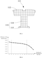
- the iron loss of the above stator lamination is greater than or equal to 1.8W/Kg and less than or equal to 3.8W/Kg when it is magnetized to 1.6T at a frequency of 60Hz.
- the iron loss of the above stator lamination is less than or equal to 3.8W/Kg and greater than or equal to 1.8W/Kg when it is magnetized to 1.6T at a frequency of 60Hz, both the upper limit and the lower limit of the iron loss of the stator lamination when it is magnetized to 1.6T at a frequency of 60Hz are defined, and this ensures performance of the electric motor;
- the iron loss of each rotor lamination should be greater than that of each stator lamination, that is, the iron loss of the rotor lamination is at least greater than or equal to 1.8W/Kg, the cost of the material of the rotor lamination is less than the cost of the material of the stator lamination, and the cost of the material of the rotor lamination is reduced under the condition of not affecting the performance of the electric motor as much as possible, and the cost performance of the electric motor is improved.
- the performance of the material of the stator lamination is defined indirectly.
- the iron loss of the rotor lamination is not limited to the two limiting values of 1.8W/Kg and 3.8W/Kg when it is magnetized to 1.6T at a frequency of 60Hz, and is at least greater than 1.8W/Kg, as long as the performance of the electric motor is ensured, the iron loss of the rotor lamination under the above condition can be increased appropriately, and thus the cost of the material of the rotor lamination is reduced, and the cost performance of the electric motor provided by the present embodiment is improved.
- the condition of measuring the iron loss for example, the stator lamination is magnetized to 1.7T at a frequency of 60Hz, further falls within the protection scope of the present application.
- 1.6T represents 1.6 Tesla
- 3.8W/Kg represents 3.8 watts per kilogram.
- the iron loss of the above rotor lamination is less than or equal to 12.5W/Kg when it is magnetized to 1.6T at a frequency of 60Hz.
- the iron loss of the above rotor lamination should be less than or equal to 12.5W/Kg when it is magnetized to 1.6T at a frequency of 60Hz, and the upper limit of the iron loss of the rotor lamination when it is magnetized to 1.6T at a frequency of 60Hz is defined. Since the iron loss of a rotor is determined by the material of the rotor under the same condition, the material of the rotor plays an important role in the manufacturing cost of the electric motor, it is necessary to find the upper limit of the iron loss of the rotor lamination suitable in a certain environment, to reduce the manufacturing cost of the electric motor as much as possible while the efficiency of the electric motor is met.
- the iron loss of the rotor lamination can be defined, when the rotor lamination is magnetized to 1.6T at a frequency of 60Hz, the iron loss of the rotor lamination should be less than or equal to 12.5W/Kg, and then the selection for the material of the rotor lamination is defined.
- the iron loss of the rotor lamination should be less than or equal to 12.5W/Kg when it is magnetized to 1.6T at a frequency of 60Hz, the selection for the material of the rotor lamination is further defined, and the cost of the electric motor can be decreased as much as possible under the condition of ensuring the working efficiency of the electric motor.
- the iron loss of the above rotor lamination is greater than or equal to 2.4W/Kg when it is magnetized to 1.6T at a frequency of 60Hz.
- the iron loss of the above rotor lamination should be greater than or equal to 2.4W/Kg when it is magnetized to 1.6T at a frequency of 60Hz, which makes a specific definition to the lower limit of the iron loss of the rotor lamination when it is magnetized to 1.6T at a frequency of 60Hz. Since the material of the rotor determines the cost of the electric motor and the iron loss of the rotor under the same condition, the iron loss of the rotor plays an important role in the efficiency of the electric motor. Therefore, it is necessary to find the lower limit of the iron loss of the rotor lamination suitable in a certain environment, to improve the efficiency of the electric motor as much as possible within an acceptable range of the cost of the electric motor.
- the iron loss of the rotor lamination is greater than or equal to 2.4W/Kg, then the efficiency of the electric motor satisfies working requirements, while once the iron loss of the rotor lamination is less than 2.4W/Kg, the cost of the electric motor will increase significantly, and at the moment, the cost of the electric motor is beyond the acceptable range for a general manufacturer.
- the iron loss of the rotor lamination can be defined, when the rotor lamination is magnetized to 1.6T at a frequency of 60Hz, the iron loss of the rotor lamination should be large than or equal to 2.4W/Kg, and then the selection for the material of the rotor lamination is defined.
- the iron loss of the rotor lamination should be greater than or equal to 2.4W/Kg when it is magnetized to 1.6T at a frequency of 60Hz, the selection for the material of the rotor lamination is further defined, and the efficiency of the electric motor can be improved as much as possible within an acceptable range of the cost of the electric motor.
- the number of the above stator laminations is X
- the number of the above rotor laminations is Y, and they satisfy 1.15Y ⁇ X ⁇ 1.5Y.
- the number of the above stator laminations should be greater than that of the rotor laminations. If the number of the stator laminations is set to be X and the number of the rotor laminations is set to be Y, then X>Y.
- both the number of the stator laminations and the number of the rotor laminations will generate influence to the efficiency of the electric motor, and in addition, the iron loss of the stator lamination is less than that of the rotor lamination, the thickness of the stator iron core in the axial direction of the electric motor is equivalent to thickness of the rotor iron core in the axial direction of the electric motor, that is, the cost of the stator lamination is greater than that of the rotor lamination; in order to save cost as much as possible, the number X of the stator laminations and the number Y of the rotor laminations should be set according to actual needs, and the difference between the two should not be too significant.
- the value of the number Y of the rotor laminations is defined, and the value of Y is limited to be in a range, specifically, 1.15Y ⁇ X ⁇ 1.5Y.
- stator groove between two adjacent iron core blocks in the above plurality of iron core blocks, and the width of the notch of the stator groove is M, the minimum gap between the stator iron core and the rotor iron core is L1, and, 0.15 ⁇ L1/M ⁇ 1.5.
- the width of the notch of the stator groove is M.
- the iron core block comprises a tooth part, the top portion of the tooth part is provided with a tooth boot for limiting the stator windings wound on the tooth part, both of two adjacent tooth parts have a tooth boot close to each other at the top portions, and the distance between the two tooth boots is called the notch, and the width of the notch is M, the greater the M is, the greater the iron loss of a rotor is; if the M is too small, the performance of the electric motor will be affected, and this makes the working of the electric motor unstable.
- the minimum gap between the stator iron core and the rotor iron core is L1
- both L1 and M can obtain an appropriate value, and then the iron loss of the rotor is reduced as much as possible while the working efficiency of the electric motor is ensured.
- the width M of the notch and the minimum gap L1 between the stator iron core and the rotor iron core restrict each other and both of them are in a reasonable range, specifically, 0.15 ⁇ L1/M ⁇ 1.5, through reducing M as much as possible within a reasonable range, the value of L1 is further defined, and the iron loss of the rotor of the electric motor is reduced to the maximum extent, and thus the effect that the cost of the electric motor is reduced while the efficiency of the electric motor does not change much is achieved, and the cost performance of the electric motor is improved.
- the maximum gap between the above stator iron core and the above rotor iron core is L2, and, 0.15 ⁇ L2 ⁇ L1 ⁇ 2.
- the width of the gap between them is not a constant value.
- the minimum gap between the stator iron core and the rotor iron core is L1
- the maximum gap between the stator iron core and the rotor iron core is L2.
- the distance between the stator iron core and the rotor iron core in the centerline of the cross axis is the maximum gap L2 between the stator iron core and a rotary shaft iron core.
- L2 Similar to L1, if the value of L2 is too large, it will cause excessive magnetic leakage and reduce the efficiency of the electric motor; if the value of L2 is too small, the corresponding value of L1 will be less, and the gap between the stator iron core and the rotor iron core will be very small; when the rotor rotates, the two easily rub and collide with each other, and this results in the phenomenon of sweeping the chamber and damages the electric motor. Therefore, similar to L1, it is necessary to limit the value of L2. However, the value of L1 is limited to be in a range, and thus L2 can be limited through L1, specifically, 0.15 ⁇ L2 ⁇ L1 ⁇ 2.
- the above iron core block comprises a yoke part and a tooth part, the tooth part is connected to the yoke part, the tooth part comprises a tooth root and a tooth boot, and the tooth root is connected between the yoke part and the tooth boot; and, there is a notch between the tooth boots of two adjacent iron core blocks, and the width of the end part of the tooth boot is L3, 0.16 ⁇ L3/M ⁇ 3.
- the yoke part and the tooth part are provided on the iron core block, and the tooth part is connected to the yoke part.
- the stator iron core is formed by splicing a plurality of iron core blocks, two adjacent iron core blocks are connected through the yoke part, and the tooth parts of two adjacent iron core blocks do not contact each other.
- the tooth part comprises the tooth root and the tooth boot, and the tooth boot is connected to the yoke part through the tooth root.
- the tooth boots of the above two iron core blocks get close to each other, the gap between the two tooth boots is called the notch, the width of the notch is M, and the width of the end part of the tooth boot is L3.
- L3 can be restricted through the value of M, specifically, 0.16 ⁇ L3/M ⁇ 3.
- the plurality of iron core blocks comprise a plurality of yoke parts distributed along the circumferential direction, each yoke part comprises a convex part and a concave part distributed at the two sides of the circumferential direction, and the convex part of one yoke part extends into the concave part of the adjacent yoke part.
- the plurality of iron core blocks comprise a plurality of yoke parts distributed along the circumferential direction, the two sides of each yoke part are respectively provided with the convex part and the concave part.
- the convex part of the yoke part of each iron core block is inserted into the concave part of the adjacent iron core block, the two adjacent iron core blocks are connected to each other, and all the iron core blocks are connected and jointly form the stator iron core.
- the convex part and the concave part with mutually matching shapes on both sides of the yoke part of each iron core block in the circumferential direction two adjacent iron core blocks can be connected through the matching of the convex part and the concave part.
- the convex part of the yoke part of the same iron core block extends into the concave part of the yoke part of another iron core block, the two iron core blocks are connected together, and all the iron core blocks are connected successively and jointly form the stator iron core.
- the number of the above stator grooves is greater than or equal to 6, and less than or equal to 12.
- the above stator groove is the space between two adjacent tooth parts.
- the number of the stator grooves is equal to the number of the tooth parts, while the tooth parts and the yoke parts correspond to each other one by one, and thus the number of the stator grooves is further equal to the number of the yoke parts at the same time.
- the number of the stator windings, the slot fullness rate of the stator and the size of the space of the stator grooves have a very important influence on the performance of the stator of the electric motor, while the number of the stator windings, the slot fullness rate of the stator and the size of the space of the stator grooves can be determined by the number of the tooth parts on the stator iron core. Therefore, when the size of the stator is certain, the number of the tooth parts that the stator iron core comprises has an important influence to the performance of the electric motor.
- the number of the stator grooves is greater than or equal to 6, and less than or equal to 12.
- the number of the stator grooves in the stator iron core it is required that the number of the stator grooves should be greater than or equal to 6, and less than or equal to 12, and meanwhile, the number of the tooth parts and the number of the yoke parts on the stator iron core, which are the same with the number of the stator grooves, are further limited, and furthermore, it is ensured that the performance of the electric motor where the stator iron core is located is in a reasonable range.
- the outer diameter of the stator iron core is D1
- the outer diameter of the rotor iron core is D2, and, 0.47 ⁇ D1/D2 ⁇ 0.68.
- the above rotor iron core is disposed inside the stator ion core; when the electric motor works, the rotor iron core needs to rotate inside the stator iron core, therefore, the outer diameter of the rotor iron core should be less than the inner diameter of the stator iron core.
- the size of the outer diameter of the stator iron core determines the size of the space of the stator groove in the stator iron core, and further determines the number of the stator windings wound on the tooth part and the magnitude of magnetic force produced in the stator iron core when the electric motor works.
- the relation between the size of the rotor iron core and the size of the stator iron core is defined to ensure the efficiency of the electric motor.
- the ratio of the outer diameter D1 of the stator iron core to the outer diameter D2 of the rotor iron core has an upper limit of 0.68 and a lower limit of 0.47, i.e., 0.47 ⁇ D1/D2 ⁇ 0.68.
- the ratio of the outer diameter D1 of the stator iron core to the outer diameter D2 of the rotor iron core has an upper limit of 0.68 and a lower limit of 0.47, both the size of the stator iron core and the size of the rotor iron core are in a reasonable range, the efficiency of the electric motor is ensured, and this avoids that the stator iron core is too large or too small relative to the rotor iron core, which results in the cost waste and reduces the efficiency of the electric motor.
- the number of poles of the above electric motor is greater than or equal to 4 and less than or equal to 10.
- the number of the poles of the electric motor directly determines the power, the rotation speed, and the performance of the electric motor, and is one of the most important parameters of the electric motor. To minimize cost as much as possible while ensure the efficiency of the electric motor, it is necessary to limit the number of the poles of the electric motor.
- the number of the poles of the electric motor cannot be too small, otherwise the power of the electric motor is too small and the use of the electric motor is affected; the number of the poles in the electric motor should not be too large, a too large number of the poles will increase the manufacturing cost of the electric motor and cause unnecessary waste.
- the number of poles of the above electric motor is defined to be greater than or equal to 4 and less than or equal to 10.
- the above rotor iron core is sleeved on the inner side of the above stator iron core.
- the above rotor iron core is sleeved on the inner side of the above stator iron core; when the electric motor works, the rotor iron core rotates and works in the internal space of the stator iron core due to the influence of a magnetic force.
- the electric motor provided in the present embodiment is an inner rotor electric motor.
- the above electric motor comprises a permanent magnet motor.
- the above electric motor comprises the permanent magnet motor
- the permanent magnet motor has the advantages of high power efficiency, high power factor, low iron loss, etc., and there is little friction and noise during the working process. From multiple perspectives, the permanent magnet motor has significant advantages over other types of electric motors and is suitable for the electric motor used in the present embodiment.
- the second aspect according to the present application further provides a compressor, and the compressor comprises the electric motor provided in any of the above embodiments.
- the compressor provided by the present application comprises the electric motor according to any of the above embodiments, and therefore has all the beneficial effects of the above electric motor, which are not stated here one by one.
- the above compressor further comprises a shaft, a power unit, a main bearing and an auxiliary bearing, and, the shaft passes through the rotor iron core of the rotor, and is connected to the rotor iron core;
- the power unit comprises a piston and a cylinder, the cylinder is connected to the piston, and the piston is connected to the shaft;
- the main bearing is provided on the shaft, and located between the power unit and the electric motor;
- the auxiliary bearing is further provided at one end of the shaft, and the power unit is located between the auxiliary bearing and the main bearing.
- the shaft of the compressor passes through the shaft hole of the rotor iron core and is connected to the rotor iron core, and the shaft is connected to the power unit; when the compressor works, the cylinder of the power unit drives the piston to move, the piston brings the shaft to rotate and further brings the rotor iron core to rotate, and the main bearing and the auxiliary bearing are respectively located at the two ends of the power unit along the direction of the shaft.
- the third aspect according to the present application further provides a refrigeration apparatus, and the above refrigeration apparatus comprises the electric motor provided in any of the above embodiments, or the compressor provided in any of the above embodiments.
- the refrigeration apparatus is a typical electrical device that requires the use of an electric motor.
- a conventional refrigeration apparatus requires the use of the compressor, while only a few special refrigeration apparatuses are not equipped with the compressor, instead, other types of equipment are directly driven by the electric motor for cooling and refrigeration.
- the refrigeration apparatus provided by the present application comprises the electric motor of the above embodiments, or the compressor of the above embodiments, and therefore, the above refrigeration apparatus has all the beneficial effects of the above electric motor or the above compressor, which are not stated here one by one.
- 100 electric motor
- 110 stator iron core
- 111 iron core block
- 112 yoke part
- 113 tooth part
- 114 tooth root
- 115 tooth boot
- 116 notch
- 120 rotor iron core
- 121 permanent magnet
- 130 stator winding
- 200 compressor
- 210 shaft
- 220 power unit
- 222 piston
- 240 auxiliary bearing.
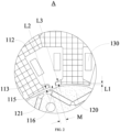
- the first aspect according to the present application provides an electric motor 100, including: a stator iron core 110 and a rotor iron core 120, and the stator iron core 110 comprises a plurality of iron core blocks 111 spliced in a circumferential direction, each iron core block 111 comprises a plurality of stator laminations stacked in an axial direction of the electric motor 100; and the rotor iron core 120 comprises a plurality of rotor laminations stacked in an axial direction; and the number of the stator laminations is greater than that of the rotor laminations, and the iron loss of each stator lamination is less than that of each rotor lamination.
- the electric motor 100 provided by the present application comprises the stator iron core 110 and the rotor iron core 120.
- the stator iron core 110 comprises a plurality of iron core blocks 111, and the stator iron core 110 can be rendered by connecting all the iron core blocks 111 in the circumferential direction.
- the stator iron core 110 comprises a tooth part 113, and a stator winding 130 is wound on the tooth part 113; in order to improve the performance of the electric motor 100, in the case that other conditions are not changed, it is necessary to wind as many turns of stator windings 130 as possible on the same tooth part 113.
- the tooth part 113 is usually located at the inner side of the stator iron core 110 and extends towards the center of the inner hollow place of the stator iron core 110, and when the stator winding 130 is wound on the tooth part 113, this will usually be affected by other parts of the stator iron core 110, and then winding the stator winding 130 becomes difficult; the distance between two adjacent tooth parts 113 is fixed and narrow, and thus, when the stator winding 130 is wound on a tooth part 113, this is usually blocked by other adjacent tooth parts 113 of the tooth part 113, this structure further impedes the winding of the stator windings 130, and the assembling difficulty for the electric motor 100 is increased, and the slot fullness rate of the stator iron core 110 is affected.
- the stator iron core 110 comprises a plurality of iron core blocks 111, when the iron core blocks 111 are not connected to be the stator iron core 110, each iron core block 111 is respectively wound with the stator winding 130, the iron core block 111 comprises the tooth part 113, the tooth part 113 is directly exposed, and thus, when the stator winding 130 is wound, it will not be impeded by other parts of the stator iron core 110; if each iron core block 111 only comprises one tooth part 113, when the stator winding 130 is wound on the tooth part 113, there are not adjacent tooth parts 113 on the two sides of the tooth part 113, the operation space becomes large, the winding difficulty of the stator windings 130 is greatly reduced, and as many turns of stator windings 130 as possible can be wound on the tooth part 113, and finally, the iron core blocks 111 after the winding of all the stator windings 130 is completed are spliced along the circumferential direction, and thus a complete stator is obtained.
- the iron loss of the stator iron core 110 and the rotor iron core 120 is rendered due to multiple aspects, while the eddy current loss is one of the most important sources of the iron loss.
- the stator iron core 110 comprises a plurality of iron core blocks 111, each iron core block 111 comprises a plurality of stator laminations stacked in the axial direction of the electric motor 100; the rotor iron core 120 comprises a plurality of rotor laminations stacked in the axial direction of the electric motor 100.
- Such method that the iron core block 111 is stacked by stator laminations and the rotor iron core 120 is stacked by the rotor laminations can effectively reduce the eddy current loss of the stator iron core 110 and the rotor iron core 120, and improve the energy and efficiency of the electric motor 100.
- the iron loss of the rotor is usually greatly less than that of the stator, and therefore, through disposing the iron loss of each rotor lamination to be greater than that of each stator lamination, under the condition of ensuring the performance of the electric motor 100, the cost of the rotor can be reduced, and furthermore, the cost of the electric motor 100 is reduced, and the cost performance of the electric motor 100 is improved.
- the number of the stator laminations is greater than that of the rotor laminations, and the iron loss of the rotor iron core 120 is greatly less than that of the stator iron core 110, and therefore, under the condition of ensuring the performance and the efficiency of the electric motor 100, the requirements for the material and structure of the rotor iron core 120 can be appropriately relaxed to reduce the cost of the electric motor 100.
- the axial thicknesses of the stator and the rotor of the electric motor 100 are substantially the same, that is, the axial thickness of the stator iron core 110 is equivalent to the axial thickness of the rotor iron core 120.
- the iron core block 111 of the stator iron core 110 comprises a plurality of stator laminations stacked in the axial direction of the electric motor 100
- the rotor iron core 120 comprises a plurality of rotor laminations stacked in the axial direction of the electric motor 100.
- the number of the stator laminations is disposed to be greater than that of the rotor laminations, since the axial thickness of the stator iron core 110 is equivalent to the axial thickness of the rotor iron core 120, the thickness of the stator lamination should be less than the thickness of the rotor lamination, and it is understandable that the thinner the stator lamination or the rotor lamination is and the greater the number of the stacked stator laminations or the stacked rotor laminations is, the less the iron loss of the stator iron core 110 or the rotor iron core 120 is and the higher the manufacturing and assembling cost is; therefore, under the condition of ensuring the efficiency of the electric motor 100, the requirements for the manufacturing and assembling conditions of the rotor iron core 120 which has a less iron loss can be appropriately relaxed, the thickness of the rotor lamination is increased while the number of the rotor laminations is reduced, and the manufacturing cost of the rotor is reduced under the condition of ensuring
- the stator iron core 110 comprises a plurality of iron core blocks 111 spliced along the circumferential direction, and thus the difficulty of winding the stator windings 130 on the stator iron core 110 is reduced and the slot fullness rate of the stator iron core 110 is increased, and the performance of the electric motor 100 is improved;
- the iron core block 111 comprises a plurality of stator laminations stacked in the axial direction of the electric motor 100 and the rotor iron core 120 comprises a plurality of rotor laminations stacked in the axial direction of the electric motor 100, and such a structure can effectively reduce the eddy current loss of the stator iron core 110 and the rotor iron core 120, reduce the iron loss of the electric motor 100 and improve the energy and efficiency of the electric motor 100; through the arrangement that the number of the stator laminations is greater than that of the rotor laminations, i.e., the thickness of the rotor lamination is greater than that of the stator lamination,
- the above electric motor provided by the present application can further comprise the following additional features.
- the iron loss of the above stator lamination is greater than or equal to 1.8W/Kg and less than or equal to 3.8W/Kg when it is magnetized to 1.6T at a frequency of 60Hz.
- the iron loss of the above stator lamination is less than or equal to 3.8W/Kg and greater than or equal to 1.8W/Kg when it is magnetized to 1.6T at a frequency of 60Hz, both the upper limit and the lower limit of the iron loss of the stator lamination when it is magnetized to 1.6T at a frequency of 60Hz are defined, and this ensures performance of the electric motor 100;
- the iron loss of each rotor lamination should be greater than that of each stator lamination, that is, the iron loss of the rotor lamination is at least greater than 1.8W/Kg, the cost of the material of the rotor lamination is less than the cost of the material of the stator lamination, and the cost of the material of the rotor lamination is reduced under the condition of not affecting the performance of the electric motor 100 as much as possible, and the cost performance of the electric motor 100 is improved.
- the electric motor 100 provided in the embodiment, through arranging the upper limit and the lower limit of the iron loss of the stator lamination when it is magnetized to 1.6T at a frequency of 60Hz, a specific requirement for the performance of the material of the stator lamination is set, while the iron loss of each rotor lamination should be greater than that of each stator lamination, and therefore, the performance of the material of the rotor lamination is defined indirectly.
- the iron loss of the rotor lamination is not limited to the two limiting values of 1.8W/Kg and 3.8W/Kg when it is magnetized to 1.6T at a frequency of 60Hz, and is at least greater than 1.8W/Kg, as long as the performance of the electric motor 100 is ensured, the iron loss of the rotor lamination under the above condition can be increased appropriately, and thus the cost of the material of the rotor lamination is reduced, and the cost performance of the electric motor 100 provided by the present embodiment is improved.
- the condition of measuring the iron loss for example, the stator lamination is magnetized to 1.7T at a frequency of 60Hz, further falls within the protection scope of the present application.
- 1.6T represents 1.6 Tesla
- 3.8W/Kg represents 3.8 watts per kilogram.
- the iron loss of the above rotor lamination is less than or equal to 12.5W/Kg when it is magnetized to 1.6T at a frequency of 60Hz.
- the iron loss of the above rotor lamination should be less than or equal to 12.5W/Kg when it is magnetized to 1.6T at a frequency of 60Hz, and the upper limit of the iron loss of the rotor lamination when it is magnetized to 1.6T at a frequency of 60Hz is specifically defined. Since the iron loss of a rotor is determined by the material of the rotor under the same condition, the material of the rotor plays an important role in the manufacturing cost of the electric motor 100, it is necessary to find the upper limit of the iron loss of the rotor lamination suitable in a certain environment, to reduce the manufacturing cost of the electric motor 100 as much as possible while the efficiency of the electric motor 100 is met.
- the iron loss of the rotor lamination can be defined, when the rotor lamination is magnetized to 1.6T at a frequency of 60Hz, the iron loss of the rotor lamination should be less than or equal to 12.5W/Kg, and then the selection for the material of the rotor lamination is defined.
- the electric motor 100 provided by the present embodiment, through the arrangement that the iron loss of the rotor lamination should be less than or equal to 12.5W/Kg when it is magnetized to 1.6T at a frequency of 60Hz, the selection for the material of the rotor lamination is further defined, and the cost of the electric motor 100 can be decreased as much as possible under the condition of ensuring the working efficiency of the electric motor 100.
- the iron loss of the above rotor lamination is greater than or equal to 2.4W/Kg when it is magnetized to 1.6T at a frequency of 60Hz.
- the iron loss of the above rotor lamination should be greater than or equal to 2.4W/Kg when it is magnetized to 1.6T at a frequency of 60Hz, which makes a specific definition to the lower limit of the iron loss of the rotor lamination when it is magnetized to 1.6T at a frequency of 60Hz. Since the material of the rotor determines the cost of the electric motor 100 and the iron loss of the rotor under the same condition, the iron loss of the rotor plays an important role in the efficiency of the electric motor 100. Therefore, it is necessary to find the lower limit of the iron loss of the rotor lamination suitable in a certain environment, to improve the efficiency of the electric motor 100 as much as possible within an acceptable range of the cost of the electric motor 100.
- the iron loss of the rotor lamination is greater than or equal to 2.4W/Kg, then the efficiency of the electric motor 100 satisfies working requirements, while once the iron loss of the rotor lamination is less than 2.4W/Kg, the cost of the electric motor 100 will increase significantly, and at the moment, the cost of the electric motor 100 is beyond the acceptable range for a general manufacturer.
- the iron loss of the rotor lamination can be defined, when the rotor lamination is magnetized to 1.6T at a frequency of 60Hz, the iron loss of the rotor lamination should be large than or equal to 2.4W/Kg, and then the selection for the material of the rotor lamination is defined.
- the electric motor 100 provided by the present embodiment, through the arrangement that the iron loss of the rotor lamination should be greater than or equal to 2.4W/Kg when it is magnetized to 1.6T at a frequency of 60Hz, the selection for the material of the rotor lamination is further defined, and the efficiency of the electric motor 100 can be improved as much as possible within an acceptable range of the cost of the electric motor 100.
- the number of the above stator laminations is X
- the number of the above rotor laminations is Y
- the number of the above stator laminations should be greater than that of the rotor laminations. If the number of the stator laminations is set to be X and the number of the rotor laminations is set to be Y, then X>Y.
- both the number of the stator laminations and the number of the rotor laminations will generate influence to the efficiency of the electric motor 100, and in addition, the iron loss of the stator lamination is less than that of the rotor lamination, the thickness of the stator iron core 110 in the axial direction of the electric motor 100 is equivalent to thickness of the rotor iron core 120 in the axial direction of the electric motor 100, that is, the cost of the stator lamination is greater than that of the rotor lamination; in order to save cost as much as possible, the number X of the stator laminations and the number Y of the rotor laminations should be set according to actual needs, and the difference between the two should not be too significant.
- the value of the number Y of the rotor laminations is defined, and the value of Y is limited to be in a range, specifically, 1.15Y ⁇ X ⁇ 1.5Y.
- stator groove between two adjacent iron core blocks 111 in the above plurality of iron core blocks 111, and the width of the notch 116 of the stator groove is M, the minimum gap between the stator iron core 110 and the rotor iron core 120 is L1, and, 0.15 ⁇ L1/M ⁇ 1.5.
- the width of the notch 116 of the stator groove is M.
- the iron core block 111 comprises a tooth part 113, the top portion of the tooth part 113 is provided with a tooth boot 115 for limiting the stator windings 130 wound on the tooth part 113, both of two adjacent tooth parts 113 have a tooth boot 115 close to each other at the top portions, and the distance between the two tooth boots 115 is called the notch 116, and the width of the notch 116 is M, the greater the M is, the greater the iron loss of a rotor is; if the M is too small, the performance of the electric motor 100 will be affected, and this makes the working of the electric motor 100 unstable.
- the minimum gap between the stator iron core 110 and the rotor iron core 120 is L1
- both L1 and M can obtain an appropriate value, and then the iron loss of the rotor is reduced as much as possible while the working efficiency of the electric motor 100 is ensured.
- the maximum gap between the above stator iron core 110 and the above rotor iron core 120 is L2, and, 0.15 ⁇ L2 ⁇ L1 ⁇ 2.
- stator iron core 110 and the rotor iron core 120 there is a gap between the stator iron core 110 and the rotor iron core 120, due to the structure feature of the stator iron core 110 and the rotor iron core 120, the width of the gap between them is not a constant value.
- the minimum gap between the stator iron core 110 and the rotor iron core 120 is L1
- the maximum gap between the stator iron core 110 and the rotor iron core 120 is L2.
- stator iron core 110 and the rotor iron core 120 when the direct axis of the rotor of the electric motor 100 is aligned with the centerline of the tooth part 113 of the stator of the electric motor 100, along the center line of the cross axis, the distance between the stator iron core 110 and the rotor iron core 120 in the centerline of the cross axis is the maximum gap L2 between the stator iron core 110 and a rotary shaft iron core.
- L2 Similar to L1, if the value of L2 is too large, it will cause excessive magnetic leakage and reduce the efficiency of the electric motor 100; if the value of L2 is too small, the corresponding value of L1 will be less, and the gap between the stator iron core 110 and the rotor iron core 120 will be very small; when the rotor rotates, the two easily rub and collide with each other, and this results in the phenomenon of sweeping the chamber and damages the electric motor 100. Therefore, similar to L1, it is necessary to limit the value of L2. However, the value of L1 is limited to be in a range, and thus L2 can be limited through L1, specifically, 0.15 ⁇ L2 ⁇ L1 ⁇ 2.
- the above iron core block 111 comprises a yoke part 112 and a tooth part 113, the tooth part 113 is connected to the yoke part 112, the tooth part 113 comprises a tooth root 114 and a tooth boot 115, and the tooth root 114 is connected between the yoke part 112 and the tooth boot 115; and, there is the notch 116 between the tooth boots 115 of two adjacent iron core blocks 111, and the width of the end part of the tooth boot 115 is L3, 0.16 ⁇ L3/M ⁇ 3.
- the yoke part 112 and the tooth part 113 are provided on the iron core block 111, and the tooth part 113 is connected to the yoke part 112.
- the stator iron core 110 is formed by splicing a plurality of iron core blocks 111
- two adjacent iron core blocks 111 are connected through the yoke part 112
- the tooth parts 113 of two adjacent iron core blocks 111 do not contact each other.
- the tooth part 113 comprises the tooth root 114 and the tooth boot 115, and the tooth boot 115 is connected to the yoke part 112 through the tooth root 114.
- the tooth boots 115 of the above two iron core blocks 111 get close to each other, the gap between the two tooth boots 115 is called the notch 116, the width of the notch 116 is M, and the width of the end part of the tooth boot 115 is L3.
- the width L3 of the end part of the tooth boot 115 is too large, the space for winding the stator windings 130 in the tooth part 113 will be decreased, the turns of the stator windings 113 will be decreased, and the performance of the electric motor 100 is lowered; if the width L3 of the end part of the tooth boot 115 is too small, the stator winding 130 cannot be restricted effectively, and this easily cause the detachment of the stator winding 130. Therefore, it is necessary to restrict the value of the L3. L3 can be restricted through the value of M, specifically, 0.16 ⁇ L3/M ⁇ 3.
- the plurality of iron core blocks 111 comprise a plurality of yoke parts 112 distributed along the circumferential direction, each yoke part 112 comprises a convex part and a concave part distributed at the two sides of the circumferential direction, and the convex part of one yoke part 112 extends into the concave part of the adjacent yoke part 112.
- the plurality of iron core blocks 111 comprise a plurality of yoke parts 112 distributed along the circumferential direction, the two sides of each yoke part 112 are respectively provided with the convex part and the concave part.
- the convex part of the yoke part 112 of each iron core block 111 is inserted into the concave part of the adjacent iron core block 111, the two adjacent iron core blocks 111 are connected to each other, and all the iron core blocks 111 are connected and jointly form the stator iron core 110.
- the electric motor 100 through disposing the convex part and the concave part with mutually matching shapes on both sides of the yoke part 112 of each iron core block 111 in the circumferential direction, two adjacent iron core blocks 111 can be connected through the matching of the convex part and the concave part.
- the convex part of the yoke part 112 of the same iron core block 111 extends into the concave part of the yoke part 112 of another iron core block 111, the two iron core blocks 111 are connected together, and all the iron core blocks 111 are connected successively and jointly form the stator iron core 110.
- the number of the above stator grooves is greater than or equal to 6, and less than or equal to 12.
- the above stator groove is the space between two adjacent tooth parts 113.
- the number of the stator grooves is equal to the number of the tooth parts 113, while the tooth parts 113 and the yoke parts 112 correspond to each other one by one, and thus the number of the stator grooves is further equal to the number of the yoke parts 112 at the same time.
- the number of the stator windings 130, the slot fullness rate of the stator and the size of the space of the stator grooves have a very important influence on the performance of the stator of the electric motor 100, while the number of the stator windings 130, the slot fullness rate of the stator and the size of the space of the stator grooves can be determined by the number of the tooth parts 113 on the stator iron core 110. Therefore, when the size of the stator is certain, the number of the tooth parts 113 that the stator iron core 110 comprises has an important influence to the performance of the electric motor 100.
- the number of the stator grooves is greater than or equal to 6, and less than or equal to 12.
- the electric motor 100 provided in the present embodiment, through limiting the number of the stator grooves in the stator iron core 110, it is required that the number of the stator grooves should be greater than or equal to 6, and less than or equal to 12, and meanwhile, the number of the tooth parts 113 and the number of the yoke parts 112 on the stator iron core 110, which are the same with the number of the stator grooves, are further limited, and furthermore, it is ensured that the performance of the electric motor 100 where the stator iron core 110 is located is in a reasonable range.
- the outer diameter of the stator iron core 110 is D1
- the outer diameter of the rotor iron core 120 is D2, and, 0.47 ⁇ D1/D2 ⁇ 0.68.
- the above rotor iron core 120 is disposed inside the stator ion core 110; when the electric motor 100 works, the rotor iron core 120 needs to rotate inside the stator iron core 110, therefore, the outer diameter of the rotor iron core 120 should be less than the inner diameter of the stator iron core 110.
- the size of the outer diameter of the stator iron core 110 determines the size of the space of the stator groove in the stator iron core 110, and further determines the number of the stator windings 130 wound on the tooth part 113 and the magnitude of magnetic force produced in the stator iron core 110 when the electric motor 100 works.
- the relation between the size of the rotor iron core 120 and the size of the stator iron core 110 is defined to ensure the efficiency of the electric motor 100.
- the ratio of the outer diameter D1 of the stator iron core 110 to the outer diameter D2 of the rotor iron core 120 has an upper limit of 0.68 and a lower limit of 0.47, i.e., 0.47 ⁇ D1/D2 ⁇ 0.68.
- the electric motor 100 provided in the present embodiment, through the arrangement that the ratio of the outer diameter D1 of the stator iron core 110 to the outer diameter D2 of the rotor iron core 120 has an upper limit of 0.68 and a lower limit of 0.47, both the size of the stator iron core 110 and the size of the rotor iron core 120 are in a reasonable range, the efficiency of the electric motor 100 is ensured, and this avoids that the stator iron core 110 is too large or too small relative to the rotor iron core 120, which results in the cost waste and reduces the efficiency of the electric motor 100.
- the number of poles of the above electric motor 100 is greater than or equal to 4 and less than or equal to 10.
- the number of the poles of the electric motor 100 directly determines the power, the rotation speed, and the performance of the electric motor 100, and is one of the most important parameters of the electric motor 100. To minimize cost as much as possible while ensure the efficiency of the electric motor 100, it is necessary to limit the number of the poles of the electric motor 100.
- the number of the poles of the motor 100 cannot be too small, otherwise the power of the electric motor 100 is too small and the use of the electric motor 100 is affected; the number of the poles in the electric motor 100 should not be too large, a too large number of the poles will increase the manufacturing cost of the electric motor 100 and cause unnecessary waste.
- the number of poles of the above electric motor 100 is defined to be greater than or equal to 4 and less than or equal to 10.
- the rotor iron core 120 comprises a certain number of rotor laminations stacked along the axial direction of the electric motor 100, and the rotor laminations are silicon steel sheets.
- a mounting groove is provided in the rotor iron core 120, and the mounting groove is located inside the rotor iron core 120 and distributed along the circumferential direction of the rotor iron core 120; a plurality of permanent magnets 121 are inserted into the mounting groove and then mounted inside the rotor iron core 120, and furthermore, magnetic poles which number is twice of the number of the poles of the electric motor 100 and which polarities change alternatively in the circumferential direction are formed on the rotor.
- the above rotor iron core 120 is sleeved on the inner side of the above stator iron core 110.
- the above rotor iron core 120 is sleeved on the inner side of the above stator iron core 110; when the electric motor 100 works, the rotor iron core 120 rotates and works in the internal space of the stator iron core 110 due to the influence of a magnetic force.
- the electric motor 100 provided in the present embodiment is an inner rotor electric motor 100.
- the above electric motor 100 comprises a permanent magnet motor.
- the above electric motor 100 comprises the permanent magnet motor
- the permanent magnet motor has the advantages of high power efficiency, high power factor, low iron loss, etc., and there is little friction and noise during the working process. From multiple perspectives, the permanent magnet motor has significant advantages over other types of electric motors 100 and is suitable for the electric motor 100 used in the present embodiment.
- the second aspect according to the present application further provides a compressor 200, and the compressor 200 comprises the electric motor 100 provided in any of the above embodiments.
- the compressor 200 provided by the present application comprises the electric motor 100 according to any of the above embodiments, and therefore has all the beneficial effects of the above electric motor 100, which are not stated here one by one.
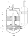
- the above compressor 200 further comprises a shaft 210, a power unit 220, a main bearing 230 and an auxiliary bearing 240, and, the shaft 210 is provided at the rotor iron core 120 of the rotor, and is connected to the rotor iron core 120;
- the power unit 220 comprises a piston 222 and a cylinder 221, the cylinder 221 is connected to the piston 222, and the piston 222 is connected to the shaft 210;
- the main bearing 230 is provided on the shaft 210, and located between the power unit 220 and the electric motor 100;
- the auxiliary bearing 240 is further provided at one end of the shaft 210, and the power unit 220 is located between the auxiliary bearing 240 and the main bearing 230.
- the shaft 210 of the compressor 200 passes through the shaft hole of the rotor iron core 120 and is connected to the rotor iron core 120, and the shaft 210 is connected to the power unit 220; when the compressor 220 works, the cylinder 221 of the power unit 220 drives the piston 222 to move, the piston 222 brings the shaft 210 to rotate and further brings the rotor iron core 120 to rotate, and the main bearing 230 and the auxiliary bearing 240 are respectively located at the two ends of the power unit 220 along the direction of the shaft 210.
- the third aspect according to the present application further provides a refrigeration apparatus, and the above refrigeration apparatus comprises the electric motor 100 provided in any of the above embodiments, or the compressor 200 provided in any of the above embodiments.
- the refrigeration apparatus is a typical electrical device that requires the use of an electric motor 100.
- a conventional refrigeration apparatus requires the use of the compressor 200, while only a few special refrigeration apparatuses are not equipped with the compressor 200, instead, other types of equipment are directly driven by the electric motor 100 for cooling and refrigeration.
- the refrigeration apparatus provided by the present application comprises the electric motor 100 of the above embodiments, or the compressor 200 of the above embodiments, and therefore, the above refrigeration apparatus has all the beneficial effects of the above electric motor 100 or the above compressor 200, which are not stated here one by one.
- the phrase of "a plurality of” indicates two or more than two, unless otherwise explicitly specified or defined.
- the terms of “mounting”, “connected to”, “connected”, “fixing” and the like should be understood in a broad sense, for example, “connected” may be a fixed connection, and may further be a removable connection, or an integral connection; and “connected to” may be a direct connection and may further be an indirect connection through an intermediate medium.
- a person of ordinary skills in the art could understand the specific meanings of the terms in the present application according to specific situations.
- the descriptions of the phrases “one embodiment”, “some embodiments” and “specific embodiments” and the like mean that the specific features, structures, materials or characteristics described in combination with the embodiment(s) or example(s) are included in at least one embodiment or example of the present application.
- the schematic representation of the above phrases does not necessarily refer to the same embodiment or example.
- the particular features, structures, materials or characteristics described may be combined in a suitable manner in any one or more of the embodiments or examples.
Landscapes
- Engineering & Computer Science (AREA)
- Power Engineering (AREA)
- Mechanical Engineering (AREA)
- General Engineering & Computer Science (AREA)
- Iron Core Of Rotating Electric Machines (AREA)
Applications Claiming Priority (2)
| Application Number | Priority Date | Filing Date | Title |
|---|---|---|---|
| CN202111468256.1A CN114123561A (zh) | 2021-12-03 | 2021-12-03 | 电机、压缩机和制冷设备 |
| PCT/CN2022/079187 WO2023097916A1 (zh) | 2021-12-03 | 2022-03-04 | 电机、压缩机和制冷设备 |
Publications (2)
| Publication Number | Publication Date |
|---|---|
| EP4439927A1 true EP4439927A1 (de) | 2024-10-02 |
| EP4439927A4 EP4439927A4 (de) | 2025-04-09 |
Family
ID=80366258
Family Applications (1)
| Application Number | Title | Priority Date | Filing Date |
|---|---|---|---|
| EP22899739.1A Pending EP4439927A4 (de) | 2021-12-03 | 2022-03-04 | Elektromotor, verdichter und kühlvorrichtung |
Country Status (3)
| Country | Link |
|---|---|
| EP (1) | EP4439927A4 (de) |
| CN (1) | CN114123561A (de) |
| WO (1) | WO2023097916A1 (de) |
Families Citing this family (1)
| Publication number | Priority date | Publication date | Assignee | Title |
|---|---|---|---|---|
| CN114123561A (zh) * | 2021-12-03 | 2022-03-01 | 广东美芝制冷设备有限公司 | 电机、压缩机和制冷设备 |
Family Cites Families (13)
| Publication number | Priority date | Publication date | Assignee | Title |
|---|---|---|---|---|
| US6069422A (en) * | 1998-03-06 | 2000-05-30 | Fasco Industries, Inc. | Noise reduction motor design and method |
| JP3326127B2 (ja) * | 1998-12-04 | 2002-09-17 | 株式会社三井ハイテック | 積層鉄心の製造方法 |
| JP2001268873A (ja) * | 2000-03-21 | 2001-09-28 | Matsushita Electric Ind Co Ltd | 圧縮機用モータ及びその応用機器 |
| CN201781393U (zh) * | 2010-09-11 | 2011-03-30 | 广东美芝精密制造有限公司 | 压缩机用永磁同步电动机 |
| CN205178812U (zh) * | 2015-05-08 | 2016-04-20 | 德昌电机(深圳)有限公司 | 风机及其单相外转子无刷电机 |
| CN105790458B (zh) * | 2016-04-13 | 2018-07-27 | 广东美芝制冷设备有限公司 | 永磁电机及具有其的压缩机、空调器 |
| CN106329852A (zh) * | 2016-10-21 | 2017-01-11 | 珠海格力节能环保制冷技术研究中心有限公司 | 定子冲片的设计方法、定子冲片、定子铁芯及电机 |
| CN206226141U (zh) * | 2016-11-28 | 2017-06-06 | 广东美芝精密制造有限公司 | 电机和具有其的压缩机 |
| KR102549047B1 (ko) * | 2018-07-27 | 2023-06-28 | 미쓰비시덴키 가부시키가이샤 | 전동기, 압축기 및 공기 조화 장치 |
| CN209709769U (zh) * | 2019-06-24 | 2019-11-29 | 广东威灵汽车部件有限公司 | 定子、电机、压缩机、制冷设备及车辆 |
| CN212486356U (zh) * | 2020-02-28 | 2021-02-05 | 丹佛斯(天津)有限公司 | 转子、内置式永磁电机以及压缩机 |
| CN114123561A (zh) * | 2021-12-03 | 2022-03-01 | 广东美芝制冷设备有限公司 | 电机、压缩机和制冷设备 |
| CN216390618U (zh) * | 2021-12-03 | 2022-04-26 | 广东美芝制冷设备有限公司 | 电机、压缩机和制冷设备 |
-
2021
- 2021-12-03 CN CN202111468256.1A patent/CN114123561A/zh active Pending
-
2022
- 2022-03-04 WO PCT/CN2022/079187 patent/WO2023097916A1/zh not_active Ceased
- 2022-03-04 EP EP22899739.1A patent/EP4439927A4/de active Pending
Also Published As
| Publication number | Publication date |
|---|---|
| WO2023097916A1 (zh) | 2023-06-08 |
| CN114123561A (zh) | 2022-03-01 |
| EP4439927A4 (de) | 2025-04-09 |
Similar Documents
| Publication | Publication Date | Title |
|---|---|---|
| EP4117153B1 (de) | Schenkelpol-hybridanregungsmotor | |
| EP4236034A1 (de) | Statorblech, statorkern, motor, verdichter und kühlvorrichtung | |
| US20220181920A1 (en) | End winding flux motor | |
| WO2022110311A1 (zh) | 定子铁芯、定子、永磁同步电机、压缩机和制冷设备 | |
| EP4439927A1 (de) | Elektromotor, verdichter und kühlvorrichtung | |
| CN110620456B (zh) | 转子铁芯、永磁电机及压缩机 | |
| WO2023108910A1 (zh) | 转子组件、电机和电器设备 | |
| CN110912297B (zh) | 电机和压缩机 | |
| DE60235685D1 (de) | Innen- und Aussenläufer elektrischer Motor mit Luftspaltringwicklung | |
| CN112003399A (zh) | 转子、电机、压缩机及空调器、车辆 | |
| CN117353479A (zh) | 定子结构、电机和压缩机 | |
| CN216390618U (zh) | 电机、压缩机和制冷设备 | |
| CN219123999U (zh) | 电机、压缩机和制冷设备 | |
| CN215956145U (zh) | 内置弧型磁钢的外转子永磁同步电机 | |
| CN214314779U (zh) | 转子组件、永磁电机、压缩机和制冷设备 | |
| CN214506697U (zh) | 转子结构、电机及压缩机 | |
| WO2020019588A1 (zh) | 永磁电机、压缩机和空调器 | |
| CN115441680A (zh) | 永磁电机、压缩机及家用电器 | |
| CN111092500B (zh) | 六极转子装置及具有该六极转子装置的磁阻马达 | |
| CN114640202A (zh) | 转子组件及轴向磁通永磁电机 | |
| CN219247552U (zh) | 一种定子冲片、定子铁芯及电机 | |
| CN121356278B (zh) | 一种盘式电机 | |
| CN223785829U (zh) | 电机、风机及电器设备 | |
| CN112467910B (zh) | 表贴式无刷电机转子及电机 | |
| CN121332951A (zh) | 电机、压缩机及制冷设备 |
Legal Events
| Date | Code | Title | Description |
|---|---|---|---|
| STAA | Information on the status of an ep patent application or granted ep patent |
Free format text: STATUS: THE INTERNATIONAL PUBLICATION HAS BEEN MADE |
|
| PUAI | Public reference made under article 153(3) epc to a published international application that has entered the european phase |
Free format text: ORIGINAL CODE: 0009012 |
|
| STAA | Information on the status of an ep patent application or granted ep patent |
Free format text: STATUS: REQUEST FOR EXAMINATION WAS MADE |
|
| 17P | Request for examination filed |
Effective date: 20240628 |
|
| AK | Designated contracting states |
Kind code of ref document: A1 Designated state(s): AL AT BE BG CH CY CZ DE DK EE ES FI FR GB GR HR HU IE IS IT LI LT LU LV MC MK MT NL NO PL PT RO RS SE SI SK SM TR |
|
| DAV | Request for validation of the european patent (deleted) | ||
| DAX | Request for extension of the european patent (deleted) | ||
| A4 | Supplementary search report drawn up and despatched |
Effective date: 20250310 |
|
| RIC1 | Information provided on ipc code assigned before grant |
Ipc: H02K 1/276 20220101ALI20250304BHEP Ipc: F04B 39/00 20060101ALI20250304BHEP Ipc: F04B 35/04 20060101ALI20250304BHEP Ipc: H02K 3/42 20060101ALI20250304BHEP Ipc: H02K 3/52 20060101ALI20250304BHEP Ipc: H02K 3/12 20060101ALI20250304BHEP Ipc: H02K 1/16 20060101ALI20250304BHEP Ipc: H02K 3/28 20060101ALI20250304BHEP Ipc: H02K 1/14 20060101AFI20250304BHEP |
|
| RAP3 | Party data changed (applicant data changed or rights of an application transferred) |
Owner name: GUANGDONG MEIZHI COMPRESSOR CO., LTD. |