EP4439929A2 - Bürstenloser gleichstromgebläsemotor mit stator mit wärmeableitstruktur - Google Patents
Bürstenloser gleichstromgebläsemotor mit stator mit wärmeableitstruktur Download PDFInfo
- Publication number
- EP4439929A2 EP4439929A2 EP24167423.3A EP24167423A EP4439929A2 EP 4439929 A2 EP4439929 A2 EP 4439929A2 EP 24167423 A EP24167423 A EP 24167423A EP 4439929 A2 EP4439929 A2 EP 4439929A2
- Authority
- EP
- European Patent Office
- Prior art keywords
- blower motor
- stator
- annular protrusion
- base
- core
- Prior art date
- Legal status (The legal status is an assumption and is not a legal conclusion. Google has not performed a legal analysis and makes no representation as to the accuracy of the status listed.)
- Pending
Links
Images


Classifications
-
- H—ELECTRICITY
- H02—GENERATION; CONVERSION OR DISTRIBUTION OF ELECTRIC POWER
- H02K—DYNAMO-ELECTRIC MACHINES
- H02K3/00—Details of windings
- H02K3/32—Windings characterised by the shape, form or construction of the insulation
- H02K3/34—Windings characterised by the shape, form or construction of the insulation between conductors or between conductor and core, e.g. slot insulation
- H02K3/345—Windings characterised by the shape, form or construction of the insulation between conductors or between conductor and core, e.g. slot insulation between conductor and core, e.g. slot insulation
-
- H—ELECTRICITY
- H02—GENERATION; CONVERSION OR DISTRIBUTION OF ELECTRIC POWER
- H02K—DYNAMO-ELECTRIC MACHINES
- H02K7/00—Arrangements for handling mechanical energy structurally associated with dynamo-electric machines, e.g. structural association with mechanical driving motors or auxiliary dynamo-electric machines
- H02K7/14—Structural association with mechanical loads, e.g. with hand-held machine tools or fans
-
- B—PERFORMING OPERATIONS; TRANSPORTING
- B60—VEHICLES IN GENERAL
- B60H—ARRANGEMENTS OF HEATING, COOLING, VENTILATING OR OTHER AIR-TREATING DEVICES SPECIALLY ADAPTED FOR PASSENGER OR GOODS SPACES OF VEHICLES
- B60H1/00—Heating, cooling or ventilating devices
- B60H1/02—Heating, cooling or ventilating devices the heat being derived from the propulsion plant
- B60H1/04—Heating, cooling or ventilating devices the heat being derived from the propulsion plant from cooling liquid of the plant
- B60H1/08—Heating, cooling or ventilating devices the heat being derived from the propulsion plant from cooling liquid of the plant from other radiator than main radiator
- B60H1/10—Heating, cooling or ventilating devices the heat being derived from the propulsion plant from cooling liquid of the plant from other radiator than main radiator the other radiator being situated in a duct capable of being connected to atmosphere outside vehicle
- B60H1/12—Heating, cooling or ventilating devices the heat being derived from the propulsion plant from cooling liquid of the plant from other radiator than main radiator the other radiator being situated in a duct capable of being connected to atmosphere outside vehicle using an air blower
-
- H—ELECTRICITY
- H02—GENERATION; CONVERSION OR DISTRIBUTION OF ELECTRIC POWER
- H02K—DYNAMO-ELECTRIC MACHINES
- H02K1/00—Details of the magnetic circuit
- H02K1/06—Details of the magnetic circuit characterised by the shape, form or construction
- H02K1/12—Stationary parts of the magnetic circuit
- H02K1/16—Stator cores with slots for windings
-
- H—ELECTRICITY
- H02—GENERATION; CONVERSION OR DISTRIBUTION OF ELECTRIC POWER
- H02K—DYNAMO-ELECTRIC MACHINES
- H02K1/00—Details of the magnetic circuit
- H02K1/06—Details of the magnetic circuit characterised by the shape, form or construction
- H02K1/12—Stationary parts of the magnetic circuit
- H02K1/18—Means for mounting or fastening magnetic stationary parts on to, or to, the stator structures
- H02K1/187—Means for mounting or fastening magnetic stationary parts on to, or to, the stator structures to inner stators
-
- H—ELECTRICITY
- H02—GENERATION; CONVERSION OR DISTRIBUTION OF ELECTRIC POWER
- H02K—DYNAMO-ELECTRIC MACHINES
- H02K1/00—Details of the magnetic circuit
- H02K1/06—Details of the magnetic circuit characterised by the shape, form or construction
- H02K1/12—Stationary parts of the magnetic circuit
- H02K1/20—Stationary parts of the magnetic circuit with channels or ducts for flow of cooling medium
-
- H—ELECTRICITY
- H02—GENERATION; CONVERSION OR DISTRIBUTION OF ELECTRIC POWER
- H02K—DYNAMO-ELECTRIC MACHINES
- H02K11/00—Structural association of dynamo-electric machines with electric components or with devices for shielding, monitoring or protection
- H02K11/30—Structural association with control circuits or drive circuits
-
- H—ELECTRICITY
- H02—GENERATION; CONVERSION OR DISTRIBUTION OF ELECTRIC POWER
- H02K—DYNAMO-ELECTRIC MACHINES
- H02K21/00—Synchronous motors having permanent magnets; Synchronous generators having permanent magnets
- H02K21/12—Synchronous motors having permanent magnets; Synchronous generators having permanent magnets with stationary armatures and rotating magnets
- H02K21/22—Synchronous motors having permanent magnets; Synchronous generators having permanent magnets with stationary armatures and rotating magnets with magnets rotating around the armatures, e.g. flywheel magnetos
-
- H—ELECTRICITY
- H02—GENERATION; CONVERSION OR DISTRIBUTION OF ELECTRIC POWER
- H02K—DYNAMO-ELECTRIC MACHINES
- H02K3/00—Details of windings
- H02K3/46—Fastening of windings on the stator or rotor structure
- H02K3/52—Fastening salient pole windings or connections thereto
- H02K3/521—Fastening salient pole windings or connections thereto applicable to stators only
- H02K3/522—Fastening salient pole windings or connections thereto applicable to stators only for generally annular cores with salient poles
-
- H—ELECTRICITY
- H02—GENERATION; CONVERSION OR DISTRIBUTION OF ELECTRIC POWER
- H02K—DYNAMO-ELECTRIC MACHINES
- H02K5/00—Casings; Enclosures; Supports
- H02K5/04—Casings or enclosures characterised by the shape, form or construction thereof
- H02K5/16—Means for supporting bearings, e.g. insulating supports or means for fitting bearings in the bearing-shields
- H02K5/173—Means for supporting bearings, e.g. insulating supports or means for fitting bearings in the bearing-shields using bearings with rolling contact, e.g. ball bearings
- H02K5/1735—Means for supporting bearings, e.g. insulating supports or means for fitting bearings in the bearing-shields using bearings with rolling contact, e.g. ball bearings radially supporting the rotary shaft at only one end of the rotor
-
- H—ELECTRICITY
- H02—GENERATION; CONVERSION OR DISTRIBUTION OF ELECTRIC POWER
- H02K—DYNAMO-ELECTRIC MACHINES
- H02K7/00—Arrangements for handling mechanical energy structurally associated with dynamo-electric machines, e.g. structural association with mechanical driving motors or auxiliary dynamo-electric machines
- H02K7/08—Structural association with bearings
- H02K7/083—Structural association with bearings radially supporting the rotary shaft at both ends of the rotor
-
- H—ELECTRICITY
- H02—GENERATION; CONVERSION OR DISTRIBUTION OF ELECTRIC POWER
- H02K—DYNAMO-ELECTRIC MACHINES
- H02K9/00—Arrangements for cooling or ventilating
- H02K9/14—Arrangements for cooling or ventilating wherein gaseous cooling medium circulates between the machine casing and a surrounding mantle
- H02K9/16—Arrangements for cooling or ventilating wherein gaseous cooling medium circulates between the machine casing and a surrounding mantle wherein the cooling medium circulates through ducts or tubes within the casing
-
- H—ELECTRICITY
- H05—ELECTRIC TECHNIQUES NOT OTHERWISE PROVIDED FOR
- H05K—PRINTED CIRCUITS; CASINGS OR CONSTRUCTIONAL DETAILS OF ELECTRIC APPARATUS; MANUFACTURE OF ASSEMBLAGES OF ELECTRICAL COMPONENTS
- H05K7/00—Constructional details common to different types of electric apparatus
- H05K7/20—Modifications to facilitate cooling, ventilating, or heating
- H05K7/2089—Modifications to facilitate cooling, ventilating, or heating for power electronics, e.g. for inverters for controlling motor
- H05K7/20909—Forced ventilation, e.g. on heat dissipaters coupled to components
-
- H—ELECTRICITY
- H02—GENERATION; CONVERSION OR DISTRIBUTION OF ELECTRIC POWER
- H02K—DYNAMO-ELECTRIC MACHINES
- H02K2203/00—Specific aspects not provided for in the other groups of this subclass relating to the windings
- H02K2203/03—Machines characterised by the wiring boards, i.e. printed circuit boards or similar structures for connecting the winding terminations
-
- H—ELECTRICITY
- H02—GENERATION; CONVERSION OR DISTRIBUTION OF ELECTRIC POWER
- H02K—DYNAMO-ELECTRIC MACHINES
- H02K2203/00—Specific aspects not provided for in the other groups of this subclass relating to the windings
- H02K2203/12—Machines characterised by the bobbins for supporting the windings
-
- H—ELECTRICITY
- H02—GENERATION; CONVERSION OR DISTRIBUTION OF ELECTRIC POWER
- H02K—DYNAMO-ELECTRIC MACHINES
- H02K2211/00—Specific aspects not provided for in the other groups of this subclass relating to measuring or protective devices or electric components
- H02K2211/03—Machines characterised by circuit boards, e.g. pcb
Definitions
- the present invention relates to a blower motor used in an air conditioning system for a vehicle, etc. More specifically, the present invention relates to a blower motor applying a stator assembly with a novel structure, thereby making the blower motor compact and light weight, and also preventing overheating of the motor.
- vehicles need to introduce hot or cool air thereinto to control the temperature or humidity inside the vehicles, and the air for controlling the temperature and humidity is circulated by rotation of a blower fan.
- the blower fan is driven by a blower motor.
- the blower motor includes a rotor, a stator and a housing accommodating the stator and the rotor.
- the rotor When current is applied to a coil wound around the stator core, the rotor is rotated by electromagnetic interaction with the stator, thereby rotating a fan assembly installed in a rotating shaft of the rotor, to perform air conditioning.
- Korean Patent No. 10-1755881 discloses a structure in which a stepped portion is formed in the surface in contact with the heat sink so that air introduced into the blower motor is concentrated to devices mounted on the printed circuit board, which are the main heating source, so as to effectively dissipate heat of the devices.
- This prior art mentions a structure for cooling heat generated from the devices, but does not mention how to handle heat generated from the stator.
- the present inventors suggest a blower motor with a novel structure capable of effectively cooling heat generated from a stator assembly and a printed circuit board, and minimizing the size and weight of the motor.
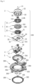
- the blower motor comprises a stator assembly 1 comprising a stator core 10, an upper insulator 11 coupled to an upper portion of the stator core 10, and a lower insulator 12 coupled to a lower portion of the stator core 10; a rotor assembly 2 rotating around the stator assembly 1; a stator block 3 to which the stator assembly 1 is coupled; a printed circuit board 4 located at a lower portion of the stator block 3; and a motor cover 5 coupled to the stator block 3.
- the stator core 10 may comprise a core base 101 having a cylindrical shape, a plurality of teeth 102 formed radially on an outer surface of the core base 101 at regular intervals, a central cylindrical body 103 located inside the core base 101 and having a central coupling hole 103A thereinside, and a plurality of through holes 105 in a space between the core base 101 and the central cylindrical body 103.
- the blower motor may further comprise a plurality of ribs 104 connecting an outer circumferential portion of the core base 101 and an inner circumferential portion of the central cylindrical body 103.
- the upper insulator 11 may comprise an upper base 111 located at an upper portion of the core base 101, upper teeth 112 for covering an upper portion of the teeth 102 for insulation, a first annular protrusion 113 protruding upwardly from the upper base 111, and a second annular protrusion 114 having an upper central space 114A and located at an upper portion of the central cylindrical body 103.
- the blower motor may further comprise a plurality of flow passages 116 between the first annular protrusion 113 and the second annular protrusion 114.
- the blower motor may further comprise a plurality of connection ribs 115 connecting the first annular protrusion 113 and the second annular protrusion 114.
- an upper bearing B1 is inserted into the upper central space 114A.
- a plurality of coil guides 117 may be formed protruding radially on an outer circumferential surface of the first annular protrusion 113 at regular intervals.
- the lower insulator 12 may comprise a lower base 121 located at a lower portion of the core base 101, lower teeth 122 for covering a lower portion of the teeth 102 for insulation, and a lower annular protrusion 123 protruding downwardly from the lower base 121.
- the lower insulator 12 may further comprise an inner support 124 having a coupling space 124A in the center and protruding toward the shaft from the lower base 121.
- a coupling guide 125 may be formed protruding upwardly in the inner support 124 at regular intervals.
- the lower annular protrusion 123 may have at least one first terminal groove 123A.
- the lower annular protrusion 123 may have at least one second terminal groove 123B.
- the present invention has an effect of providing a blower motor with a novel structure capable of effectively cooling heat generated from a stator assembly and a printed circuit board, and reducing the size of the motor and lightening the weight thereof.
- Fig. 1 is a perspective view of a blower motor according to the present invention.
- Fig. 2 is a cut-away perspective view of the blower motor in Fig. 1 taken along line A-A'.
- Fig. 3 is an exploded perspective view of a blower motor according to the present invention.
- Fig. 4 is a bottom exploded perspective view of a blower motor according to the present invention.
- the blower motor according to the present invention comprises a motor assembly 100, a flange 200 and a damper plate 300.
- the motor assembly 100 comprises a stator assembly 1, a rotor assembly 2, a stator block 3, a printed circuit board 4, and a motor cover 5.
- the motor assembly 100 is seated on the flange 200, and the damper plate 300 is coupled to the flange 200 to prevent the motor assembly 100 from dislodging.
- the stator assembly 1 comprises a stator core 10, an upper insulator 11 and a lower insulator 12.
- the stator core 10 has a core base 101 having a cylindrical shape and a plurality of teeth 102 formed radially on an outer surface of the core base 101 at regular intervals.
- the upper insulator 11 is coupled to an upper portion of the stator core 10, and the lower insulator 12 is coupled to a lower portion of the stator core 10.
- a coil C is wound around the teeth 102 according to a predetermined pattern. An end of the wound coil C is electrically connected to a first terminal T1 and a second terminal T2 protruding downwardly from the lower insulator 12.
- the rotor assembly 2 comprises a shaft 21, a rotor housing 22 having a cup shape, to which the shaft 21 is coupled and which rotates with the shaft 21, and a plurality of magnets 23 attached along an inner wall of the rotor housing 22 at regular intervals.
- the rotor assembly 2 is installed to enclose the stator assembly 1, and is rotated by a changing magnetic field generated by the stator assembly 1.
- the shaft 21 is rotatably supported by an upper bearing B1 and a lower bearing B2.
- the upper bearing B1 is installed in a central portion of the upper insulator 11.
- the lower bearing B2 is installed in a central portion of the stator block 3.
- the stator assembly 1 is coupled to an upper portion of the stator block 3, and the printed circuit board 4 is located at a lower portion of the stator block 3.
- the stator block 3 comprises a plate 30 having a circular shape, a hollow protrusion 31 protruding upwardly from a central portion of the plate 30, a protruding coupler 32 protruding radially from a periphery of the plate 30 at regular intervals, a through hole 33 formed through vertically around the hollow protrusion 31 of the plate 30, through which the first and second terminals T1, T2 pass, an insulating member 34 for closing the through hole 33, and a device groove 35 for receiving a portion in which some devices mounted on the printed circuit board 4 protrude.
- the plate 30 is made of aluminum, which has high electrical and thermal conductivity.
- the stator assembly 1 is coupled to the hollow protrusion 31 of the stator block 3.
- the lower bearing B2 rotatably supporting the shaft 21 is coupled to an inner space 31A inside the hollow protrusion 31.
- the printed circuit board 4 comprises a substrate 40 on which various devices are mounted, and a connector 41 installed on one side of the substrate 40 to be connected to an external power source.
- the first and second terminals T1, T2 are electrically connected to the substrate 40.
- the circuits on the substrate 40 are physically and electrically connected to the plate 30 of the stator block 3, which allows the circuits to be grounded.
- the motor cover 5 comprises a cover body 50 having a cup shape, a connector coupling part 51 opening a portion of one side the cover body 50, a packing part 52 along an upper periphery of the cover body 50, a plurality of damper parts 53 protruding upwardly from an upper periphery of the cover body 50 at regular intervals, a central protrusion 54 protruding upwardly from a lower central portion of the cover body 50, and a central groove 54A forming an inner space of the central protrusion 54 in a lower center of the cover body 50.
- the connector 41 is coupled to the connector coupling part 51.
- the packing part 52 made of a material such as rubber is formed around the cover body 50 and the connector coupling part 51. Accordingly, the inner space of the motor cover 5 is sealed from the outside in a state where the motor cover 5 is coupled to the stator block 3, thereby blocking the introduction of moisture from a lower portion of the motor cover 5.
- the damper part 53 made of a material such as rubber protrudes upwardly from a periphery of the cover body 50.
- the protruding coupler 32 of the stator block 3 is coupled to the damper part 53. Accordingly, the position and number of the protruding coupler 32 are set to be the same as the position and number of the damper part 53.
- the damper part 53 is located in a damper seating part 203 of the flange 200 to perform decoupling such that vibration generated from the motor assembly 100 is not transmitted to the flange 200.
- the central protrusion 54 is located in the inner space 31A of the stator block 3, such that an upper surface of the central protrusion 54 supports a lower end of the shaft 21 when the shaft 21 of the rotor assembly 2 is press fitted into the lower bearing B2.
- a jig (not illustrated) is located in the central groove 54A, which is an inner space of the central protrusion 54, such that the upper surface of the central protrusion 54 supports the lower end of the shaft 21.
- the flange 200 comprises a flange body 201 having a hole in the center, into which the motor assembly 100 is inserted, an upper protrusion 202 having an annular shape protruding upwardly along a periphery of the hole into which the motor assembly 100 is inserted, a damper seating part 203 formed in the shape of a groove at a position corresponding to the damper part 53, and a coupling protrusion 204 formed in the shape of a protrusion on a lower portion of the flange body 201 at a position corresponding to a locking part 302 of the damper plate 300.
- a portion of the rotor assembly 2 is located inside the upper protrusion 202 to rotate.
- the damper part 53 of the motor cover 5 is seated on the damper seating part 203 having a groove shape.
- the damper part 53 is a buffering member made of a material such as rubber to absorb vibration generated from the motor assembly 100.
- the damper part 53 which is seated on the damper seating part 203 of the flange 200, reduces vibration generated from the motor assembly 100.
- the damper plate 300 has an annular body 301 having a ring shape, a plurality of locking parts 302 protruding upwardly from a periphery of the annular body 301 at regular intervals, and a plurality of protrusion guides 303 protruding toward the shaft 21 from a periphery of the annular body 301 at regular intervals.
- the locking part 302 has a locking hole 302A, and the locking hole 302A is coupled to the coupling protrusion 204.
- the locking hole 302A may be modified to have a protrusion shape, and the coupling protrusion 204 may be modified to have a hole or groove shape.
- the protrusion guide 303 supports the motor cover 5 to prevent the motor assembly 100 from dislodging downwardly.
- Fig. 5 is a perspective view of a stator core 10 of a blower motor according to the present invention.
- the stator core 10 of the blower motor comprises a core base 101 having a cylindrical shape with a hollow interior, a plurality of teeth 102 formed radially from an outer periphery of the core base 101, a central cylindrical body 103 located inside the core base 101 and having a central coupling hole 103A thereinside, a plurality of ribs 104 connecting an outer circumferential portion of the core base 101 and an inner circumferential portion of the central cylindrical body 103, and a plurality of through holes 105 in a space between the core base 101 and the central cylindrical body 103.
- the stator core 10 is manufactured by continuously forming a thin electrical steel sheet by press punching and laminating the same.
- a coil C is wound around each of the teeth 102 while being insulated by the upper and lower insulators 11, 12.
- the hollow protrusion 31 of the stator block 3 is press fitted and coupled to the central coupling hole 103A inside the central cylindrical body 103.
- the plurality of through holes 105 provides air passages to dissipate heat generated from the stator core 10, etc.
- Fig. 6 is a perspective view of a stator assembly 1 of a blower motor according to the present invention.
- Fig. 7 is a bottom perspective view of a stator assembly 1 of a blower motor according to the present invention.
- the stator assembly 1 of the blower motor comprises a stator core 10, an upper insulator 11 coupled to an upper portion of the stator core 10, and a lower insulator 12 coupled to a lower portion of the stator core 10.
- the upper insulator 11 comprises an upper base 111 located at an upper portion of the core base 101 of the stator core 10, upper teeth 112 for covering an upper portion of the teeth 102 for insulation, a first annular protrusion 113 protruding upwardly from the upper base 111, a second annular protrusion 114 having an upper central space 114A and located at an upper portion of the central cylindrical body 103, a plurality of connection ribs 115 connecting the first annular protrusion 113 and the second annular protrusion 114, and a plurality of flow passages 116 between the first annular protrusion 113 and the second annular protrusion 114.
- An upper bearing B1 is coupled in the upper central space 114A. According to the present invention, the upper bearing B1 is coupled to the upper insulator 11 of the stator assembly 1. This structure may exclude the use of other components for coupling the upper bearing B1, which makes the motor compact and light weight.
- the flow passage 116 is formed to be in vertical communication with the through hole 105 of the stator core 10, which helps cooling heat generated from the stator core 10, etc.
- a coil guide 117 protrudes radially from an outer circumferential surface of the first annular protrusion 113 at regular intervals.
- the coil guide 117 allows the coil C wound around the upper teeth 112 not to deviate from the original position.
- the lower insulator 12 comprises a lower base 121 located at a lower portion of the core base 101 of the stator core 10, lower teeth 122 for covering a lower portion of the teeth 102 for insulation, a lower annular protrusion 123 protruding downwardly from the lower base 121, and an inner support 124 having a coupling space 124A in the center and protruding toward the shaft from the lower base 121.
- the lower annular protrusion 123 has at least one first terminal groove 123A and at least one second terminal groove 123B.
- the first terminal T1 is coupled to the first terminal groove 123A
- the second terminal T2 is coupled to the second terminal groove 123B.
- An end of the coil wound around the stator assembly 1 is electrically connected to the first terminal T1 and the second terminal T2.
- An end of the coil of each phase of the motor is electrically connected to the first terminal T1, and the coil connecting the neutral point of each phase is electrically connected to the second terminal T2.
- the number of the first terminals T1 and the second terminals T2 may vary depending on the specifications, number of phases, etc., of the motor.
- the first terminal groove 123A and the second terminal groove 123B may have a hole shape, instead of a groove shape, despite the names thereof.
- the hollow protrusion 31 of the stator block 3 is coupled in the coupling space 124A which is an inner space of the inner support 124.
- a coupling guide 125 (illustrated in Fig. 3 ) protruding upwardly from the inner support 124 at regular intervals may be coupled to an inside of the flow passage 116 of the stator core 10.
Landscapes
- Engineering & Computer Science (AREA)
- Power Engineering (AREA)
- Microelectronics & Electronic Packaging (AREA)
- Physics & Mathematics (AREA)
- Thermal Sciences (AREA)
- Chemical & Material Sciences (AREA)
- Combustion & Propulsion (AREA)
- Mechanical Engineering (AREA)
- Motor Or Generator Frames (AREA)
- Iron Core Of Rotating Electric Machines (AREA)
Applications Claiming Priority (1)
| Application Number | Priority Date | Filing Date | Title |
|---|---|---|---|
| KR1020230041303A KR102717142B1 (ko) | 2023-03-29 | 2023-03-29 | 방열 구조의 스테이터를 갖는 bldc 블로워 모터 |
Publications (2)
| Publication Number | Publication Date |
|---|---|
| EP4439929A2 true EP4439929A2 (de) | 2024-10-02 |
| EP4439929A3 EP4439929A3 (de) | 2024-10-09 |
Family
ID=90717659
Family Applications (1)
| Application Number | Title | Priority Date | Filing Date |
|---|---|---|---|
| EP24167423.3A Pending EP4439929A3 (de) | 2023-03-29 | 2024-03-28 | Bürstenloser gleichstromgebläsemotor mit stator mit wärmeableitstruktur |
Country Status (3)
| Country | Link |
|---|---|
| US (1) | US12395032B2 (de) |
| EP (1) | EP4439929A3 (de) |
| KR (1) | KR102717142B1 (de) |
Families Citing this family (1)
| Publication number | Priority date | Publication date | Assignee | Title |
|---|---|---|---|---|
| KR102776984B1 (ko) | 2024-12-27 | 2025-03-07 | 주식회사 케이알엠 | 냉각 성능이 개선된 bldc모터 |
Citations (1)
| Publication number | Priority date | Publication date | Assignee | Title |
|---|---|---|---|---|
| KR101755881B1 (ko) | 2015-11-05 | 2017-07-07 | 현대자동차주식회사 | 차량 공조시스템의 블로워 모터 |
Family Cites Families (10)
| Publication number | Priority date | Publication date | Assignee | Title |
|---|---|---|---|---|
| CN103460571B (zh) * | 2011-03-31 | 2016-11-16 | 并木精密宝石株式会社 | 外转子型马达 |
| CN105471127B (zh) * | 2014-05-29 | 2019-02-05 | 德昌电机(深圳)有限公司 | 电机及电机用磁芯 |
| KR101604915B1 (ko) * | 2014-08-04 | 2016-03-21 | 뉴모텍(주) | 버스바 어셈블리를 갖는 모터 |
| DE102016101538A1 (de) * | 2015-01-30 | 2016-08-04 | Johnson Electric S.A. | Elektromotor |
| DE102016205252A1 (de) | 2016-03-30 | 2017-10-05 | Mahle International Gmbh | Lageranordnung einer Motorwelle eines Elektromotors |
| JP6726631B2 (ja) | 2017-02-08 | 2020-07-22 | 株式会社ケーヒン | 空調用ブロアモータユニット |
| KR101973380B1 (ko) * | 2017-11-27 | 2019-08-26 | 효성전기주식회사 | BLDC모터용 EMC Terminal 그라운드 |
| KR102189837B1 (ko) * | 2019-08-09 | 2020-12-11 | 효성전기주식회사 | 히터싱크 기능을 갖는 스테이터블록의 접지방법 |
| KR102183072B1 (ko) | 2019-08-09 | 2020-11-25 | 효성전기주식회사 | 모터의 커넥터커버에 결합되는 커넥터의 결합방법 |
| WO2021096143A1 (ko) | 2019-11-13 | 2021-05-20 | 주식회사 아모텍 | 허브 타입 전동식 구동장치 |
-
2023
- 2023-03-29 KR KR1020230041303A patent/KR102717142B1/ko active Active
-
2024
- 2024-03-27 US US18/617,857 patent/US12395032B2/en active Active
- 2024-03-28 EP EP24167423.3A patent/EP4439929A3/de active Pending
Patent Citations (1)
| Publication number | Priority date | Publication date | Assignee | Title |
|---|---|---|---|---|
| KR101755881B1 (ko) | 2015-11-05 | 2017-07-07 | 현대자동차주식회사 | 차량 공조시스템의 블로워 모터 |
Also Published As
| Publication number | Publication date |
|---|---|
| US12395032B2 (en) | 2025-08-19 |
| EP4439929A3 (de) | 2024-10-09 |
| KR102717142B1 (ko) | 2024-10-15 |
| KR20240146396A (ko) | 2024-10-08 |
| US20240333063A1 (en) | 2024-10-03 |
Similar Documents
| Publication | Publication Date | Title |
|---|---|---|
| US7345386B2 (en) | Electric drive unit | |
| US11025144B2 (en) | Outer rotor motor having support member | |
| JP4125798B2 (ja) | 電気駆動モータ | |
| EP0682396B1 (de) | Elektronisch geschaltete Ventilatoranordnung für Fahrzeugkabinen | |
| JP6726630B2 (ja) | 空調用ブロアモータユニット | |
| EP1219006A2 (de) | Aussenläuferbürstenloser gleichstrommotor | |
| TWI643433B (zh) | 旋轉電機 | |
| EP4439929A2 (de) | Bürstenloser gleichstromgebläsemotor mit stator mit wärmeableitstruktur | |
| JP6882884B2 (ja) | モータ | |
| KR102776891B1 (ko) | 결합 구조가 개선된 스테이터 블록을 갖는 bldc 블로워 모터 | |
| KR102748033B1 (ko) | Bldc 블로워 모터의 스테이터 어셈블리 | |
| KR102748035B1 (ko) | Bldc 블로워 모터의 스테이터 어셈블리 | |
| EP4439930A1 (de) | Bürstenloser gleichstromgebläsemotor mit neuartigem statorblock | |
| KR20230123629A (ko) | 제어 기판의 냉각 구조가 개선된 블로워 모터 장치 | |
| CN108964297A (zh) | 一种电机、控制电路板及应用该电机的引擎冷却模组 | |
| KR102717137B1 (ko) | Bldc 블로워 모터의 스테이터 어셈블리 | |
| KR102748024B1 (ko) | 접지 구조가 개선된 스테이터 블록을 갖는 bldc 블로워 모터 | |
| KR102748022B1 (ko) | 조립성이 향상된 스테이터 블록을 갖는 bldc 블로워 모터 | |
| EP4439938A1 (de) | Bürstenloser gleichstromgebläsemotor mit neuartiger motorabdeckung | |
| JP7725916B2 (ja) | 電動機 | |
| US20260034849A1 (en) | Blower motor for vehicle | |
| JP2010233348A (ja) | 電動機 |
Legal Events
| Date | Code | Title | Description |
|---|---|---|---|
| PUAI | Public reference made under article 153(3) epc to a published international application that has entered the european phase |
Free format text: ORIGINAL CODE: 0009012 |
|
| STAA | Information on the status of an ep patent application or granted ep patent |
Free format text: STATUS: REQUEST FOR EXAMINATION WAS MADE |
|
| PUAL | Search report despatched |
Free format text: ORIGINAL CODE: 0009013 |
|
| 17P | Request for examination filed |
Effective date: 20240328 |
|
| AK | Designated contracting states |
Kind code of ref document: A2 Designated state(s): AL AT BE BG CH CY CZ DE DK EE ES FI FR GB GR HR HU IE IS IT LI LT LU LV MC ME MK MT NL NO PL PT RO RS SE SI SK SM TR |
|
| AK | Designated contracting states |
Kind code of ref document: A3 Designated state(s): AL AT BE BG CH CY CZ DE DK EE ES FI FR GB GR HR HU IE IS IT LI LT LU LV MC ME MK MT NL NO PL PT RO RS SE SI SK SM TR |
|
| RIC1 | Information provided on ipc code assigned before grant |
Ipc: H02K 5/173 20060101ALI20240903BHEP Ipc: H02K 3/52 20060101ALI20240903BHEP Ipc: H02K 1/20 20060101ALI20240903BHEP Ipc: H02K 1/18 20060101AFI20240903BHEP |
|
| GRAP | Despatch of communication of intention to grant a patent |
Free format text: ORIGINAL CODE: EPIDOSNIGR1 |
|
| STAA | Information on the status of an ep patent application or granted ep patent |
Free format text: STATUS: GRANT OF PATENT IS INTENDED |
|
| INTG | Intention to grant announced |
Effective date: 20260202 |