EP4440019A2 - Rückgewinnung der initialisierung einer verschlüsselungssequenz aus gefrorenen bits eines uncodierten downlink-steuerinformationsvektors - Google Patents
Rückgewinnung der initialisierung einer verschlüsselungssequenz aus gefrorenen bits eines uncodierten downlink-steuerinformationsvektors Download PDFInfo
- Publication number
- EP4440019A2 EP4440019A2 EP24167054.6A EP24167054A EP4440019A2 EP 4440019 A2 EP4440019 A2 EP 4440019A2 EP 24167054 A EP24167054 A EP 24167054A EP 4440019 A2 EP4440019 A2 EP 4440019A2
- Authority
- EP
- European Patent Office
- Prior art keywords
- scrambling sequence
- vector
- downlink signal
- initialization vector
- sequence initialization
- Prior art date
- Legal status (The legal status is an assumption and is not a legal conclusion. Google has not performed a legal analysis and makes no representation as to the accuracy of the status listed.)
- Pending
Links
Images




Classifications
-
- H—ELECTRICITY
- H04—ELECTRIC COMMUNICATION TECHNIQUE
- H04L—TRANSMISSION OF DIGITAL INFORMATION, e.g. TELEGRAPHIC COMMUNICATION
- H04L1/00—Arrangements for detecting or preventing errors in the information received
- H04L1/004—Arrangements for detecting or preventing errors in the information received by using forward error control
- H04L1/0056—Systems characterized by the type of code used
- H04L1/0057—Block codes
-
- H—ELECTRICITY
- H03—ELECTRONIC CIRCUITRY
- H03M—CODING; DECODING; CODE CONVERSION IN GENERAL
- H03M13/00—Coding, decoding or code conversion, for error detection or error correction; Coding theory basic assumptions; Coding bounds; Error probability evaluation methods; Channel models; Simulation or testing of codes
- H03M13/27—Coding, decoding or code conversion, for error detection or error correction; Coding theory basic assumptions; Coding bounds; Error probability evaluation methods; Channel models; Simulation or testing of codes using interleaving techniques
- H03M13/2778—Interleaver using block-wise interleaving, e.g. the interleaving matrix is sub-divided into sub-matrices and the permutation is performed in blocks of sub-matrices
-
- H—ELECTRICITY
- H03—ELECTRONIC CIRCUITRY
- H03M—CODING; DECODING; CODE CONVERSION IN GENERAL
- H03M13/00—Coding, decoding or code conversion, for error detection or error correction; Coding theory basic assumptions; Coding bounds; Error probability evaluation methods; Channel models; Simulation or testing of codes
- H03M13/03—Error detection or forward error correction by redundancy in data representation, i.e. code words containing more digits than the source words
- H03M13/05—Error detection or forward error correction by redundancy in data representation, i.e. code words containing more digits than the source words using block codes, i.e. a predetermined number of check bits joined to a predetermined number of information bits
- H03M13/13—Linear codes
-
- H—ELECTRICITY
- H03—ELECTRONIC CIRCUITRY
- H03M—CODING; DECODING; CODE CONVERSION IN GENERAL
- H03M13/00—Coding, decoding or code conversion, for error detection or error correction; Coding theory basic assumptions; Coding bounds; Error probability evaluation methods; Channel models; Simulation or testing of codes
- H03M13/63—Joint error correction and other techniques
- H03M13/635—Error control coding in combination with rate matching
-
- H—ELECTRICITY
- H04—ELECTRIC COMMUNICATION TECHNIQUE
- H04L—TRANSMISSION OF DIGITAL INFORMATION, e.g. TELEGRAPHIC COMMUNICATION
- H04L1/00—Arrangements for detecting or preventing errors in the information received
- H04L1/004—Arrangements for detecting or preventing errors in the information received by using forward error control
- H04L1/0045—Arrangements at the receiver end
- H04L1/0052—Realisations of complexity reduction techniques, e.g. pipelining or use of look-up tables
-
- H—ELECTRICITY
- H04—ELECTRIC COMMUNICATION TECHNIQUE
- H04L—TRANSMISSION OF DIGITAL INFORMATION, e.g. TELEGRAPHIC COMMUNICATION
- H04L1/00—Arrangements for detecting or preventing errors in the information received
- H04L1/004—Arrangements for detecting or preventing errors in the information received by using forward error control
- H04L1/0056—Systems characterized by the type of code used
- H04L1/0067—Rate matching
-
- H—ELECTRICITY
- H04—ELECTRIC COMMUNICATION TECHNIQUE
- H04L—TRANSMISSION OF DIGITAL INFORMATION, e.g. TELEGRAPHIC COMMUNICATION
- H04L1/00—Arrangements for detecting or preventing errors in the information received
- H04L1/004—Arrangements for detecting or preventing errors in the information received by using forward error control
- H04L1/0056—Systems characterized by the type of code used
- H04L1/0071—Use of interleaving
-
- H—ELECTRICITY
- H04—ELECTRIC COMMUNICATION TECHNIQUE
- H04L—TRANSMISSION OF DIGITAL INFORMATION, e.g. TELEGRAPHIC COMMUNICATION
- H04L1/00—Arrangements for detecting or preventing errors in the information received
- H04L1/004—Arrangements for detecting or preventing errors in the information received by using forward error control
- H04L1/0072—Error control for data other than payload data, e.g. control data
Definitions
- Accelerating decoding processes to extract valid operational information is critical to achieving ultra-reliable and low latency communications (URLLC) for a normal user equipment (UE) and/or an efficient multi-UE testing system.
- URLLC ultra-reliable and low latency communications
- the method may include receiving a downlink signal from a base station and determining an input-output relation of polar encoding based on a vector of the downlink signal.
- the method may include performing an interleaving operation with a matrix and the input-output relation to obtain an interleaved vector and utilizing rate matching with the interleaved vector to determine a scrambling sequence of the downlink signal.
- the method may include utilizing a reverse sequence generator with the scrambling sequence to determine a scrambling sequence initialization vector for the scrambling sequence, and performing one or more actions based on the scrambling sequence initialization vector.
- the downlink signal may include one of: a physical broadcast channel signal, ora physical downlink control channel signal.
- Utilizing rate matching with the interleaved vector to determine the scrambling sequence of the downlink signal may comprise: determining the scrambling sequence of the downlink signal based on the interleaved vector and a variable that depends on a rate matching scheme.
- Utilizing the reverse sequence generator with the scrambling sequence to determine the scrambling sequence initialization vector for the scrambling sequence may comprises: multiplying the scrambling sequence and a parity check matrix to determine the scrambling sequence initialization vector.
- the device may include one or more memories and one or more processors coupled to the one or more memories.
- the one or more processors may be configured to receive a downlink signal from a base station and determine an input-output relation of polar encoding based on an uncoded downlink control information vector of the downlink signal.
- the one or more processors may be configured to perform an interleaving operation with a matrix and the input-output relation to obtain an interleaved vector and utilize rate matching with the interleaved vector to determine a scrambling sequence of the downlink signal.
- the one or more processors may be configured to utilize a reverse sequence generator with the scrambling sequence to determine a scrambling sequence initialization vector for the scrambling sequence, and perform one or more actions based on the scrambling sequence initialization vector.
- the one or more processors, to utilize the reverse sequence generator with the scrambling sequence to determine the scrambling sequence initialization vector for the scrambling sequence may be configured to: determine the scrambling sequence initialization vector based on the uncoded downlink control information vector of the downlink signal.
- the one or more processors, to utilize the reverse sequence generator with the scrambling sequence to determine the scrambling sequence initialization vector for the scrambling sequence may be configured to: process specific bits of the uncoded downlink control information vector and a parity check matrix, with a belief propagation model, to determine results; and multiply an inverse matrix and the results to determine the scrambling sequence initialization vector for the scrambling sequence.
- the one or more processors, to perform the one or more actions based on the scrambling sequence initialization vector may be configured to: decode the downlink signal based on the scrambling sequence initialization vector.
- the one or more processors, to perform the one or more actions based on the scrambling sequence initialization vector may be configured to: perform the one or more actions based on the scrambling sequence initialization vector and without performing a descrambling operation.
- the downlink signal may include downlink control information.
- the downlink signal may be a New Radio downlink control signal.
- Some implementations described herein relate to a non-transitory computer-readable medium that stores a set of instructions.
- the set of instructions when executed by one or more processors of a device, may cause the device to receive a downlink signal from a base station, where the downlink signal includes one of a physical broadcast channel signal or a physical downlink control channel signal.
- the set of instructions when executed by one or more processors of the device, may cause the device to determine an input-output relation of polar encoding based on a vector of the downlink signal and perform an interleaving operation with a matrix and the input-output relation to obtain an interleaved vector.
- the set of instructions when executed by one or more processors of the device, may cause the device to utilize rate matching with the interleaved vector to determine a scrambling sequence of the downlink signal and utilize a reverse sequence generator with the scrambling sequence to determine a scrambling sequence initialization vector for the scrambling sequence.
- the set of instructions when executed by one or more processors of the device, may cause the device to perform one or more actions based on the scrambling sequence initialization vector.
- the one or more instructions, that cause the device to determine the input-output relation of polar encoding based on the vector of the downlink signal, may cause the device to: multiply the vector and a generator matrix to determine the input-output relation.
- the one or more instructions, that cause the device to perform the interleaving operation with the matrix and the input-output relation to obtain the interleaved vector may cause the device to: multiply the matrix and the input-output relation to obtain the interleaved vector.
- the one or more instructions, that cause the device to utilize rate matching with the interleaved vector to determine the scrambling sequence of the downlink signal may cause the device to: determine the scrambling sequence of the downlink signal based on the interleaved vector and a variable that depends on a rate matching scheme.
- the one or more instructions, that cause the device to utilize the reverse sequence generator with the scrambling sequence to determine the scrambling sequence initialization vector for the scrambling sequence may cause the device to: multiply the scrambling sequence and a parity check matrix to determine the scrambling sequence initialization vector.
- the one or more instructions, that cause the device to utilize the reverse sequence generator with the scrambling sequence to determine the scrambling sequence initialization vector for the scrambling sequence may cause the device to: determine the scrambling sequence initialization vector based on the vector of the downlink signal.
- Decoding downlink signals (e.g., physical downlink control channel (PDCCH) signals) via blind detection is one of the most computing resource intensive and time-consuming processing tasks of a testing system.
- a control channel element consisting of six resource element groups (REGs), is commonly used to carry downlink control information (DCI).
- Multiple CCEs (e.g., one, two, four, eight, sixteen, and/or the like) are allocated for a PDCCH candidate depending on a DCI size and channel conditions.
- a corresponding aggregation level (AL) is used to count a quantity of the CCEs.
- a base station may fix certain CCE indices for a particular UE (e.g., emulated by the testing system), the UE cannot determine exactly which set of CCEs will be used to transmit the PDCCH carrying a specific DCI format. In this case, multiple blind decoding processes are required by combining different ALs with specific starting CCE indices and DCI sizes for successful DCI decoding.
- a polar encoding operation can be expressed in a vector-matrix multiplication form.
- a vector u ⁇ F 2 N may be an uncoded bit vector containing information bits and redundant bits. Indexes of information bits in the vector u may be selected from an index set , whereas indexes of redundant bits may be selected from an index set .
- d uG
- G F ⁇ n
- F 1 0 1 1
- ⁇ a Kronecker product
- G G -1
- NR New Radio
- a length of the codeword after rate-matching by E may be denoted by a vector b ⁇ F 2 E .
- the resulting vector b may be scrambled by a scrambling sequence c ⁇ F 2 E , which results in a vector b ⁇ ⁇ F 2 E .
- n ID E ⁇ 0,1, ..., 65535 ⁇ equals a parameter pdcch-DMRS-ScramblingID if configured
- n RNTI is equal to C-RNTI if a parameter pdcch-DMRS-ScramblingID is configured.
- a descrambling operation may be skipped during the detection process. This may alter the decoded data but may enable performance of a single decoding operation instead of 65,536 decoding operations.
- One approach to recover a scrambling sequence initialization vector from specific bits of uncoded DCI without a descrambling operation is to use an exhaustive search, where candidate vectors for each possible initialization vector are generated and a candidate vector, with bits that match frozen bits of an uncoded DCI vector, is selected.
- an exhaustive search where candidate vectors for each possible initialization vector are generated and a candidate vector, with bits that match frozen bits of an uncoded DCI vector, is selected.
- computing resources e.g., processing resources, memory resources, communication resources, and/or the like
- networking resources e.g., networking resources, and/or the like associated with performing unnecessary and computationally intensive decoding operations, performing an unnecessary descrambling operation, performing an exhaustive search for a scrambling sequence initialization vector, and/or the like.
- the testing system may receive a downlink signal from a base station and may determine an input-output relation of polar encoding based on a vector of the downlink signal.
- the device may perform an interleaving operation with a matrix and the input-output relation to obtain an interleaved vector and may utilize rate matching with the interleaved vector to determine a scrambling sequence of the downlink signal.
- the device may utilize a reverse sequence generator with the scrambling sequence to determine a scrambling sequence initialization vector for the scrambling sequence and may perform one or more actions based on the scrambling sequence initialization vector.
- the testing system recovers scrambling sequence initialization vector from frozen bits of an uncoded DCI vector, without performing a descrambling operation.
- the testing system may determine a scrambling sequence initialization vector from specific bits of an uncoded DCI vector without performing a descrambling operation and without using an exhaustive search.
- the testing system may be utilized with a high signal-to-noise ratio (SNR), where bit values at specific bit locations of the uncoded DCI vector without descrambling are known. This, in turn, conserves computing resources, networking resources, and/or the like that would otherwise have been consumed in performing unnecessary and computationally intensive decoding operations, performing an unnecessary descrambling operation, performing an exhaustive search for a scrambling sequence initialization vector, and/or the like.
- SNR signal-to-noise ratio
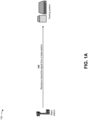
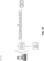
- Figs. 1A-1F are diagrams of an example 100 associated with recovering a scrambling sequence initialization vector from frozen bits of an uncoded DCI vector.
- example 100 includes a base station associated with a testing system.
- the testing system may recover a scrambling sequence initialization vector from frozen bits of an uncoded DCI vector. Further details of the base station and the testing system are provided elsewhere herein.
- the testing system may receive a downlink signal from the base station.
- the base station may generate the downlink signal.
- the downlink signal may include a physical broadcast channel signal (PBCH), a PDCCH signal, and/or the like.
- the downlink signal may include an uncoded DCI vector.
- the downlink signal may include a signal on a physical channel that carries DCI, and may include data identifying a number of the symbols (L), transport format, resource allocation, an uplink (UL) scheduling assignment (e.g., UL grants), scheduling assignments, and/or other control information.
- the base station may provide the downlink signal to the testing system, and the testing system may receive the downlink signal from the base station.
- the testing system may continuously receive multiple downlink signals from the base station, may periodically receive multiple downlink signals from the base station, may receive multiple downlink signals from the base station based on providing requests for the downlink signals to the base station, and/or the like.
- a polar encoding operation can be expressed in a vector-matrix multiplication form.
- a vector u ⁇ F 2 N u may denote an uncoded bit vector containing information bits and redundant bits. Indexes of information bits in the vector u may be selected from an index set , whereas indexes of redundant bits may be selected from an index set .
- G F ⁇ n
- F 1 0 1 1
- ⁇ a Kronecker product.
- G G -1
- NR New Radio
- the base station may apply sub-block interleaving and rate matching to the encoded codeword.
- a length of the codeword after rate-matching by E may be denoted by a vector b ⁇ F 2 E .
- the base station may scramble the resulting vector b with a scrambling sequence c ⁇ F 2 E , which results in a vector b ⁇ ⁇ F 2 E .
- the parameter n ID E ⁇ 0,1, ..., 65535 ⁇ equals a parameter pdcch-DMRS-ScramblingID if configured, and n RNTI is equal to C-RNTI if a parameter pdcch-DMRS-ScramblingID is configured.
- the scrambling operation may generate an uncoded DCI vector ( q ) of the downlink signal.
- the testing system may determine input-output relation ( r ) of polar encoding based on the vector q of the downlink signal.
- the testing system may generate the input vector c 0 from the uncoded DCI vector q ⁇ F 2 N , for N ⁇ M .
- the testing system may determine the vector c 0 from the uncoded DCI vector q , when only is given and without using an exhaustive search.
- the testing system may calculate c 0 in terms of the uncoded DCI vector q .
- the testing system may perform an interleaving operation with a matrix ( D ) and the input-output relation ( r ) to obtain an interleaved vector ( r' ).
- the testing system may utilize rate matching with the interleaved vector ( r ' ) to determine the scrambling sequence ( s ).
- the testing system may utilize a modified version of equation (9) and the matrix D to reflect the additional interleaver operations.
- the testing system may utilize a reverse sequence generator with the scrambling sequence ( s ) to determine the scrambling sequence initialization vector ( c 0 ).
- the equations (20) and (21) imply that given the uncoded DCI vector q , the testing system may calculate the scrambling sequence initialization vector c 0 by vector-matrix multiplication.
- the testing system may utilize a belief propagation (BP) model to recover the erased elements of the uncoded DCI vector q.
- BP belief propagation
- the testing system may express the uncoded DCI vector q in terms of the scrambling sequence initialization vector c 0 .
- Equations (26) and (27) may be interpreted as an encoding operation for a linear block code with a generator matrix Z.
- BEC binary erasure channel
- the testing system may calculate the scrambling sequence initialization vector c 0 based on equation (20), equation (21), or equation (24) depending on the rate-matching scheme and interleaver properties.
- the testing system may then calculate the scrambling sequence initialization vector c 0 by substituting q or q ⁇ with q ⁇ or ( q ⁇ ) ⁇ in equation (20), equation (21), or equation (24), respectively, depending on the rate-matching scheme and interleaver properties
- the testing system may perform the scrambling sequence generation in NR and vector-matrix multiplication form as follows. If q NR ⁇ F 2 N denotes a vector obtained from a scrambling sequence c ⁇ F 2 E ′ , which is generated in accordance with NR specifications as described above in connection with equation (25), then equation (26) may be updated to express q NR as: c 0 X 2 N c X 2 N c + 31 ⁇ X 2 , ML N c + ⁇ E ′ / 31 ⁇ 31 D T ⁇ N G ⁇ Z 2 , where matrices X 1 N c and X 2 N c may be formed using the polynomials as described above and a vector x 1,0 may be formed in accordance with the initialization of x 1 described above.
- a vector u ⁇ F 2 N may include frozen bits, i.e., u A c ⁇ F 2 N ⁇ K , and a CRC-attached, RNTI masked, and interleaved DCI bit vector, i.e., u A ⁇ F 2 K .
- the vector y may be generated by extracting the bits from y ′ A c .
- the extracted bits may be provided in and may be marked as erasure.
- y may be formed as a log-likelihood ratio (LLR) vector, where is filled with LLR values corresponding to values of y ' with indexes from the set .
- the remaining LLR values, may be set to zero.
- the testing system may then calculate the scrambling sequence initialization vector c 0 by substituting q or q ⁇ with q ⁇ NR or ( q ⁇ NR ) ⁇ in equation (20), equation (21), or equation (24), respectively, depending on the rate-matching scheme and interleaver properties.
- the testing system may perform one or more actions based on the scrambling sequence initialization vector ( c 0 ). For example, when performing the one or more actions based on the scrambling sequence initialization vector ( c 0 ), the testing system may decode the downlink signal based on the scrambling sequence initialization vector. The testing system may utilize the decoded downlink signal to perform additional testing of the downlink signal and/or the base station. In some implementations, when performing the one or more actions based on the scrambling sequence initialization vector ( c 0 ), the testing system may perform the one or more actions based on the scrambling sequence initialization vector and without performing a descrambling operation.
- the testing system recovers a scrambling sequence initialization vector from frozen bits of an uncoded DCI vector, without performing a descrambling operation.
- the testing system may determine a scrambling sequence initialization vector from specific bits of an uncoded DCI vector without performing descrambling operation and without using exhaustive search.
- the testing system may be utilized with a high SNR, where bit values at specific bit locations of the uncoded DCI vector without descrambling are known. This, in turn, conserves computing resources, networking resources, and/or the like that would otherwise have been consumed in performing unnecessary and computationally intensive decoding operations, performing an unnecessary descrambling operation, performing an exhaustive search for a scrambling sequence initialization vector, and/or the like.
- Figs. 1A-1F are provided as an example. Other examples may differ from what is described with regard to Figs. 1A-1F .
- the number and arrangement of devices shown in Figs. 1A-1F are provided as an example. In practice, there may be additional devices, fewer devices, different devices, or differently arranged devices than those shown in Figs. 1A-1F .
- two or more devices shown in Figs. 1A-1F may be implemented within a single device, or a single device shown in Figs. 1A-1F may be implemented as multiple, distributed devices.
- a set of devices (e.g., one or more devices) shown in Figs. 1A-1F may perform one or more functions described as being performed by another set of devices shown in Figs. 1A-1F .
- Fig. 2 is a diagram of an example environment 200 in which systems and/or methods described herein may be implemented.
- the environment 200 may include a base station 210, a testing system 220, and/or a network 230.
- Devices and/or elements of the environment 200 may interconnect via wired connections and/or wireless connections.
- the base station 210 may support, for example, a cellular radio access technology (RAT).
- the base station 210 may include one or more base stations (e.g., base transceiver stations, radio base stations, node Bs, eNodeBs (eNBs), gNodeBs (gNBs), base station subsystems, cellular sites, cellular towers, access points, transmit receive points (TRPs), radio access nodes, macrocell base stations, microcell base stations, picocell base stations, femtocell base stations, or similar types of devices) and other network entities that can support wireless communication for a user equipment (UE).
- UE user equipment
- the base station 210 may transfer traffic between a UE (e.g., using a cellular RAT), one or more base stations (e.g., using a wireless interface or a backhaul interface, such as a wired backhaul interface), and/or a core network.
- the base station 210 may provide one or more cells that cover geographic areas.
- the base station 210 may perform scheduling and/or resource management for a UE covered by the base station 210 (e.g., a UE covered by a cell provided by the base station 210).
- the base station 210 may be controlled or coordinated by a network controller, which may perform load balancing, network-level configuration, and/or other operations.
- the network controller may communicate with the base station 210 via a wireless or wireline backhaul.
- the base station 210 may include a network controller, a self-organizing network (SON) module or component, or a similar module or component.
- the base station 210 may perform network control, scheduling, and/or network management functions (e.g., for uplink, downlink, and/or sidelink communications of a UE covered by the base station 210).
- SON self-organizing network
- the testing system 220 may include one or more devices capable of receiving, generating, storing, processing, and/or providing information, as described elsewhere herein.
- the testing system 220 may include a communication device and/or a computing device.
- the testing system 220 may be utilized for functional testing, system integration testing, capacity testing, and stress testing of multiple cells (e.g., provided by the base stations 210), and may emulate thousands of UEs.
- the testing system 220 may emulate wireless communication devices, mobile phones, laptop computers, tablet computers, desktop computers, gaming consoles, set-top boxes, wearable communication devices (e.g., smart wristwatches, smart eyeglasses, head mounted displays, or virtual reality headsets), or similar types of devices.
- the network 230 may include one or more wired and/or wireless networks.
- the network 230 may include a cellular network (e.g., a fifth generation (5G) network, a fourth generation (4G) network, a long-term evolution (LTE) network, a third generation (3G) network, a code division multiple access (CDMA) network, etc.), a public land mobile network (PLMN), a local area network (LAN), a wide area network (WAN), a metropolitan area network (MAN), a telephone network (e.g., the Public Switched Telephone Network (PSTN)), a private network, an ad hoc network, an intranet, the Internet, a fiber optic-based network, and/or a combination of these or other types of networks.
- the network 230 enables communication among the devices of environment 200.
- the number and arrangement of devices and networks shown in Fig. 2 are provided as an example. In practice, there may be additional devices and/or networks, fewer devices and/or networks, different devices and/or networks, or differently arranged devices and/or networks than those shown in Fig. 2 . Furthermore, two or more devices shown in Fig. 2 may be implemented within a single device, or a single device shown in Fig. 2 may be implemented as multiple, distributed devices. Additionally, or alternatively, a set of devices (e.g., one or more devices) of the environment 200 may perform one or more functions described as being performed by another set of devices of the environment 200.
- a set of devices e.g., one or more devices
- Fig. 3 is a diagram of example components of a device 300, which may correspond to the base station 210 and/or the testing system 220.
- the base station 210 and/or the testing system 220 may include one or more devices 300 and/or one or more components of the device 300.
- the device 300 may include a bus 310, a processor 320, a memory 330, an input component 340, an output component 350, and a communication interface 360.
- the bus 310 includes one or more components that enable wired and/or wireless communication among the components of the device 300.
- the bus 310 may couple together two or more components of Fig. 3 , such as via operative coupling, communicative coupling, electronic coupling, and/or electric coupling.
- the processor 320 includes a central processing unit, a graphics processing unit, a microprocessor, a controller, a microcontroller, a digital signal processor, a field-programmable gate array, an application-specific integrated circuit, and/or another type of processing component.
- the processor 320 is implemented in hardware, firmware, or a combination of hardware and software.
- the processor 320 includes one or more processors capable of being programmed to perform one or more operations or processes described elsewhere herein.
- the memory 330 includes volatile and/or nonvolatile memory.
- the memory 330 may include random access memory (RAM), read only memory (ROM), a hard disk drive, and/or another type of memory (e.g., a flash memory, a magnetic memory, and/or an optical memory).
- the memory 330 may include internal memory (e.g., RAM, ROM, or a hard disk drive) and/or removable memory (e.g., removable via a universal serial bus connection).
- the memory 330 may be a non-transitory computer-readable medium.
- the memory 330 stores information, instructions, and/or software (e.g., one or more software applications) related to the operation of the device 300.
- the memory 330 includes one or more memories that are coupled to one or more processors (e.g., the processor 320), such as via the bus 310.
- the input component 340 enables the device 300 to receive input, such as user input and/or sensed input.
- the input component 340 may include a touch screen, a keyboard, a keypad, a mouse, a button, a microphone, a switch, a sensor, a global positioning system sensor, an accelerometer, a gyroscope, and/or an actuator.
- the output component 350 enables the device 300 to provide output, such as via a display, a speaker, and/or a light-emitting diode.
- the communication interface 360 enables the device 300 to communicate with other devices via a wired connection and/or a wireless connection.
- the communication interface 360 may include a receiver, a transmitter, a transceiver, a modem, a network interface card, and/or an antenna.
- the device 300 may perform one or more operations or processes described herein.
- a non-transitory computer-readable medium e.g., the memory 330
- the processor 320 may execute the set of instructions to perform one or more operations or processes described herein.
- execution of the set of instructions, by one or more processors 320 causes the one or more processors 320 and/or the device 300 to perform one or more operations or processes described herein.
- hardwired circuitry may be used instead of or in combination with the instructions to perform one or more operations or processes described herein.
- the processor 320 may be configured to perform one or more operations or processes described herein.
- implementations described herein are not limited to any specific combination of hardware circuitry and software.
- the number and arrangement of components shown in Fig. 3 are provided as an example.
- the device 300 may include additional components, fewer components, different components, or differently arranged components than those shown in Fig. 3 .
- a set of components (e.g., one or more components) of the device 300 may perform one or more functions described as being performed by another set of components of the device 300.
- Fig. 4 is a flowchart of an example process 400 for recovering a scrambling sequence initialization vector from frozen bits of an uncoded DCI vector.
- one or more process blocks of Fig. 4 may be performed by a device (e.g., the testing system 220). In some implementations, one or more process blocks of Fig. 4 may be performed by another device or a group of devices separate from or including the device. Additionally, or alternatively, one or more process blocks of Fig. 4 may be performed by one or more components of the device 300, such as the processor 320, the memory 330, the input component 340, the output component 350, and/or the communication interface 360.
- process 400 may include receiving a downlink signal from a base station (block 410).
- the device may receive a downlink signal from a base station, as described above.
- the downlink signal includes one of a physical broadcast channel signal, or a physical downlink control channel signal.
- the downlink signal includes downlink control information.
- the downlink signal is a New Radio downlink control signal.
- process 400 may include determining an input-output relation of polar encoding based on a vector of the downlink signal (block 420).
- the device may determine an input-output relation of polar encoding based on a vector of the downlink signal, as described above.
- the vector of the downlink signal is an uncoded downlink control information vector.
- determining the input-output relation of polar encoding based on the vector of the downlink signal includes multiplying the vector and a generator matrix to determine the input-output relation.
- process 400 may include performing an interleaving operation with a matrix and the input-output relation to obtain an interleaved vector (block 430).
- the device may perform an interleaving operation with a matrix and the input-output relation to obtain an interleaved vector, as described above.
- performing the interleaving operation with the matrix and the input-output relation to obtain the interleaved vector includes multiplying the matrix and the input-output relation to obtain the interleaved vector.
- process 400 may include utilizing rate matching with the interleaved vector to determine a scrambling sequence of the downlink signal (block 440).
- the device may utilize rate matching with the interleaved vector to determine a scrambling sequence of the downlink signal, as described above.
- utilizing rate matching with the interleaved vector to determine the scrambling sequence of the downlink signal includes determining the scrambling sequence of the downlink signal based on the interleaved vector and a variable that depends on a rate matching scheme.
- process 400 may include utilizing a reverse sequence generator with the scrambling sequence to determine a scrambling sequence initialization vector for the scrambling sequence (block 450).
- the device may utilize a reverse sequence generator with the scrambling sequence to determine a scrambling sequence initialization vector for the scrambling sequence, as described above.
- utilizing the reverse sequence generator with the scrambling sequence to determine the scrambling sequence initialization vector for the scrambling sequence includes multiplying the scrambling sequence and a parity check matrix to determine the scrambling sequence initialization vector.
- utilizing the reverse sequence generator with the scrambling sequence to determine the scrambling sequence initialization vector for the scrambling sequence includes determining the scrambling sequence initialization vector based on the uncoded downlink control information vector of the downlink signal. In some implementations, utilizing the reverse sequence generator with the scrambling sequence to determine the scrambling sequence initialization vector for the scrambling sequence includes processing specific bits of the uncoded downlink control information vector and a parity check matrix, with a belief propagation model, to determine results, and multiplying an inverse matrix and the results to determine the scrambling sequence initialization vector for the scrambling sequence.
- process 400 may include performing one or more actions based on the scrambling sequence initialization vector (block 460).
- the device may perform one or more actions based on the scrambling sequence initialization vector, as described above.
- performing the one or more actions based on the scrambling sequence initialization vector includes decoding the downlink signal based on the scrambling sequence initialization vector.
- performing the one or more actions based on the scrambling sequence initialization vector includes performing the one or more actions based on the scrambling sequence initialization vector and without performing a descrambling operation.
- process 400 may include additional blocks, fewer blocks, different blocks, or differently arranged blocks than those depicted in Fig. 4 . Additionally, or alternatively, two or more of the blocks of process 400 may be performed in parallel.
- the term "component” is intended to be broadly construed as hardware, firmware, or a combination of hardware and software. It will be apparent that systems and/or methods described herein may be implemented in different forms of hardware, firmware, and/or a combination of hardware and software. The actual specialized control hardware or software code used to implement these systems and/or methods is not limiting of the implementations. Thus, the operation and behavior of the systems and/or methods are described herein without reference to specific software code - it being understood that software and hardware can be used to implement the systems and/or methods based on the description herein.
- satisfying a threshold may, depending on the context, refer to a value being greater than the threshold, greater than or equal to the threshold, less than the threshold, less than or equal to the threshold, equal to the threshold, and/or the like, depending on the context.
- the terms “has,” “have,” “having,” or the like are intended to be open-ended terms. Further, the phrase “based on” is intended to mean “based, at least in part, on” unless explicitly stated otherwise. Also, as used herein, the term “or” is intended to be inclusive when used in a series and may be used interchangeably with “and/or,” unless explicitly stated otherwise (e.g., if used in combination with “either” or “only one of').
Landscapes
- Engineering & Computer Science (AREA)
- Physics & Mathematics (AREA)
- Probability & Statistics with Applications (AREA)
- Theoretical Computer Science (AREA)
- Computer Networks & Wireless Communication (AREA)
- Signal Processing (AREA)
- Mathematical Physics (AREA)
- Mobile Radio Communication Systems (AREA)
- Error Detection And Correction (AREA)
Applications Claiming Priority (1)
| Application Number | Priority Date | Filing Date | Title |
|---|---|---|---|
| US18/128,707 US12191886B2 (en) | 2023-03-30 | 2023-03-30 | Recovering scrambling sequence initialization from frozen bits of an uncoded downlink control information vector |
Publications (2)
| Publication Number | Publication Date |
|---|---|
| EP4440019A2 true EP4440019A2 (de) | 2024-10-02 |
| EP4440019A3 EP4440019A3 (de) | 2024-10-09 |
Family
ID=90572131
Family Applications (1)
| Application Number | Title | Priority Date | Filing Date |
|---|---|---|---|
| EP24167054.6A Pending EP4440019A3 (de) | 2023-03-30 | 2024-03-27 | Rückgewinnung der initialisierung einer verschlüsselungssequenz aus gefrorenen bits eines uncodierten downlink-steuerinformationsvektors |
Country Status (2)
| Country | Link |
|---|---|
| US (2) | US12191886B2 (de) |
| EP (1) | EP4440019A3 (de) |
Cited By (1)
| Publication number | Priority date | Publication date | Assignee | Title |
|---|---|---|---|---|
| CN119835633A (zh) * | 2025-03-14 | 2025-04-15 | 杰创智能科技股份有限公司 | 用户配置信息获取方法、装置、设备及存储介质 |
Family Cites Families (6)
| Publication number | Priority date | Publication date | Assignee | Title |
|---|---|---|---|---|
| BR112016021434A2 (pt) * | 2014-03-19 | 2017-08-15 | Huawei Tech Co Ltd | Método de equiparação de taxa de código polar e aparelho de equiparação de taxa |
| EP3209075B1 (de) | 2014-11-07 | 2019-05-29 | Huawei Technologies Co., Ltd. | Verfahren, vorrichtung und system zur datenübertragung |
| CN108631923B (zh) * | 2017-03-24 | 2020-11-17 | 华为技术有限公司 | 传输信息的方法、网络设备和终端设备 |
| US10686469B2 (en) * | 2017-05-15 | 2020-06-16 | Qualcomm Incorporated | Payload size ambiguity and false alarm rate reduction for polar codes |
| US11258535B2 (en) * | 2017-06-16 | 2022-02-22 | Lg Electronics Inc. | Method and apparatus for transmitting information |
| US12598563B2 (en) * | 2018-09-26 | 2026-04-07 | Interdigital Patent Holdings, Inc. | Synchronization block association and system information reception |
-
2023
- 2023-03-30 US US18/128,707 patent/US12191886B2/en active Active
-
2024
- 2024-03-27 EP EP24167054.6A patent/EP4440019A3/de active Pending
- 2024-11-13 US US18/946,175 patent/US20250070802A1/en active Pending
Cited By (1)
| Publication number | Priority date | Publication date | Assignee | Title |
|---|---|---|---|---|
| CN119835633A (zh) * | 2025-03-14 | 2025-04-15 | 杰创智能科技股份有限公司 | 用户配置信息获取方法、装置、设备及存储介质 |
Also Published As
| Publication number | Publication date |
|---|---|
| EP4440019A3 (de) | 2024-10-09 |
| US20240333311A1 (en) | 2024-10-03 |
| US20250070802A1 (en) | 2025-02-27 |
| US12191886B2 (en) | 2025-01-07 |
Similar Documents
| Publication | Publication Date | Title |
|---|---|---|
| JP7471357B2 (ja) | 符号化方法、復号方法、装置、および装置 | |
| EP3562071A1 (de) | Verfahren und vorrichtung zur codierung und decodierung von polarcodes | |
| US20200145023A1 (en) | Polar code encoding method and apparatus, polar code decoding method and apparatus, and device | |
| CN108365848A (zh) | 一种极性码的译码方法和装置 | |
| EP3637647A1 (de) | Codierungsverfahren, -vorrichtung und -gerät | |
| CN108462554A (zh) | 一种极性码的传输方法和装置 | |
| US20260031929A1 (en) | Encoding and decoding method and apparatus | |
| US11296723B2 (en) | Methods and apparatuses for data processing in communication system | |
| US20250070802A1 (en) | Recovering scrambling sequence initialization from frozen bits of an uncoded downlink control information vector | |
| EP3731418A1 (de) | Decodierungsverfahren und -vorrichtung | |
| CN109257140A (zh) | 一种极化信道可靠度排序的方法、极化码编码方法及装置 | |
| EP3148142A1 (de) | Decodierungsverfahren und -vorrichtung | |
| CN111490798A (zh) | 译码的方法和译码装置 | |
| EP4440018A1 (de) | Rückgewinnung der initialisierung einer verschlüsselungssequenz aus gefrorenen bits eines uncodierten downlink-steuerinformationsvektors | |
| EP3840272A1 (de) | Ressourcenmappingverfahren und -vorrichtung | |
| EP3657708B1 (de) | Codierungsverfahren und vorrichtung | |
| US11689218B2 (en) | Decoding method and apparatus based on polar code in communication system | |
| EP4340231A1 (de) | Polarcodecodierungsverfahren und decodierungsverfahren und -vorrichtungen | |
| US11362677B2 (en) | Channel encoding method and encoding apparatus | |
| WO2018146554A1 (en) | Method and device for distributed error detection with polar codes | |
| US12355562B2 (en) | Channel reencoding to reduce invalid physical downlink control channel signals | |
| KR102689928B1 (ko) | 통신 시스템에서 폴라 코드에 기초한 디코딩 방법 및 장치 | |
| EP4546730A1 (de) | Datenverarbeitungsverfahren und -vorrichtung sowie vorrichtung | |
| KR20240059559A (ko) | 레이트 매칭 자동 인코더를 위한 방법 및 시스템 |
Legal Events
| Date | Code | Title | Description |
|---|---|---|---|
| PUAI | Public reference made under article 153(3) epc to a published international application that has entered the european phase |
Free format text: ORIGINAL CODE: 0009012 |
|
| STAA | Information on the status of an ep patent application or granted ep patent |
Free format text: STATUS: THE APPLICATION HAS BEEN PUBLISHED |
|
| PUAL | Search report despatched |
Free format text: ORIGINAL CODE: 0009013 |
|
| AK | Designated contracting states |
Kind code of ref document: A2 Designated state(s): AL AT BE BG CH CY CZ DE DK EE ES FI FR GB GR HR HU IE IS IT LI LT LU LV MC ME MK MT NL NO PL PT RO RS SE SI SK SM TR |
|
| AK | Designated contracting states |
Kind code of ref document: A3 Designated state(s): AL AT BE BG CH CY CZ DE DK EE ES FI FR GB GR HR HU IE IS IT LI LT LU LV MC ME MK MT NL NO PL PT RO RS SE SI SK SM TR |
|
| RIC1 | Information provided on ipc code assigned before grant |
Ipc: H04W 72/232 20230101ALI20240904BHEP Ipc: H03M 13/00 20060101ALI20240904BHEP Ipc: H03M 13/13 20060101ALI20240904BHEP Ipc: H04L 1/00 20060101AFI20240904BHEP |
|
| STAA | Information on the status of an ep patent application or granted ep patent |
Free format text: STATUS: REQUEST FOR EXAMINATION WAS MADE |
|
| 17P | Request for examination filed |
Effective date: 20250408 |