EP4440173A1 - Knotensystem für ein zellulares tdd-netzwerk - Google Patents
Knotensystem für ein zellulares tdd-netzwerk Download PDFInfo
- Publication number
- EP4440173A1 EP4440173A1 EP23164993.0A EP23164993A EP4440173A1 EP 4440173 A1 EP4440173 A1 EP 4440173A1 EP 23164993 A EP23164993 A EP 23164993A EP 4440173 A1 EP4440173 A1 EP 4440173A1
- Authority
- EP
- European Patent Office
- Prior art keywords
- pattern
- time slots
- node
- uplink
- downlink
- Prior art date
- Legal status (The legal status is an assumption and is not a legal conclusion. Google has not performed a legal analysis and makes no representation as to the accuracy of the status listed.)
- Pending
Links
Images


Classifications
-
- H—ELECTRICITY
- H04—ELECTRIC COMMUNICATION TECHNIQUE
- H04W—WIRELESS COMMUNICATION NETWORKS
- H04W72/00—Local resource management
- H04W72/04—Wireless resource allocation
- H04W72/044—Wireless resource allocation based on the type of the allocated resource
- H04W72/0446—Resources in time domain, e.g. slots or frames
-
- H—ELECTRICITY
- H04—ELECTRIC COMMUNICATION TECHNIQUE
- H04L—TRANSMISSION OF DIGITAL INFORMATION, e.g. TELEGRAPHIC COMMUNICATION
- H04L5/00—Arrangements affording multiple use of the transmission path
- H04L5/003—Arrangements for allocating sub-channels of the transmission path
- H04L5/0048—Allocation of pilot signals, i.e. of signals known to the receiver
-
- H—ELECTRICITY
- H04—ELECTRIC COMMUNICATION TECHNIQUE
- H04L—TRANSMISSION OF DIGITAL INFORMATION, e.g. TELEGRAPHIC COMMUNICATION
- H04L5/00—Arrangements affording multiple use of the transmission path
- H04L5/003—Arrangements for allocating sub-channels of the transmission path
- H04L5/0078—Timing of allocation
-
- H—ELECTRICITY
- H04—ELECTRIC COMMUNICATION TECHNIQUE
- H04L—TRANSMISSION OF DIGITAL INFORMATION, e.g. TELEGRAPHIC COMMUNICATION
- H04L5/00—Arrangements affording multiple use of the transmission path
- H04L5/14—Two-way operation using the same type of signal, i.e. duplex
- H04L5/1469—Two-way operation using the same type of signal, i.e. duplex using time-sharing
-
- H—ELECTRICITY
- H04—ELECTRIC COMMUNICATION TECHNIQUE
- H04W—WIRELESS COMMUNICATION NETWORKS
- H04W16/00—Network planning, e.g. coverage or traffic planning tools; Network deployment, e.g. resource partitioning or cells structures
- H04W16/02—Resource partitioning among network components, e.g. reuse partitioning
- H04W16/12—Fixed resource partitioning
-
- H—ELECTRICITY
- H04—ELECTRIC COMMUNICATION TECHNIQUE
- H04W—WIRELESS COMMUNICATION NETWORKS
- H04W88/00—Devices specially adapted for wireless communication networks, e.g. terminals, base stations or access point devices
- H04W88/08—Access point devices
Definitions
- the present invention relates to a first and a second node for a cellular network operating in Time Division Duplex (TDD) mode in a frequency range, the nodes serving adjacent first and second cells of the cellular network.
- TDD Time Division Duplex
- a base station In cellular TDD networks, a base station (“node”) communicates with user equipments (“UEs”) in its cell in successive radio frames, and in each radio frame according to a specific pattern of uplink and downlink time slots, with a mixed or "special" time slot interspersed as a guard period between a downlink and an uplink time slot to account for propagation delays.
- UEs user equipments
- the 5G-NR standard provides a dynamic TDD mode in which the number of uplink and downlink time slots in a pattern can change from frame to frame.
- different TDD patterns can be used, e.g., to adapt an RMR network to different uplink/downlink throughput needs in cells covering rural areas, city areas or station/shunting areas.
- the uplink in one cell may cause interference to the downlink in the neighbouring cell ("UE to UE interference"), and the downlink in one cell may cause interference to the uplink in the neighbouring cell (“node to node interference").
- UE to UE interference interference to the downlink in the neighbouring cell
- node to node interference interference to the uplink in the neighbouring cell
- Dynamic TDD which allows for a rapid reconfiguration of time slots between uplink and downlink modes to account for short term uplink and downlink traffic requirements, makes this worse.
- the invention provides for a system comprising a first and a second node for a cellular network operating in TDD mode in a frequency range, the nodes serving adjacent first and second cells of the cellular network, which is characterised in that
- the system of the invention creates a novel operating mode of fractional frequency re-use within only a part of the TDD pattern that reigns the frames of the communication channel. Limiting each node's freedom in resource block allocation to separate parts of the frequency range only for those time slots that differ in communication mode effectively reduces the risk of crosslink interference without unduly affecting the traffic capacity of the cells.
- the first and second patterns are synchronised in time, which maximises allocation freedom for each node.
- the first part is separated from the second part by at least one resource block.
- the separation by at least one resource block creates a temporary "guard band" in frequency between potentially conflicting TDD communications in the two adjacent cells. The slight decrease in allocation space for the nodes is by far outweighed by the dramatic increase in crosslink interference suppression introduced by the guard band.
- the first part may, e.g., be separated from the second part by two to six resource blocks, preferably by four resource blocks.
- resource blocks preferably by four resource blocks.
- a subcarrier spacing of 15 KHz and 12 subcarriers per resource block 50 resource blocks à 180 KHz frequency band width, with mutual 20 KHz spacing, cover the frequency range.
- Donating two to six, in particular four, resource blocks out of 50 for creating the guard band is a small price for effective crosslink interference suppression in return.
- each pattern has a given number of uplink and a given number of downlink time slots
- the uplink, downlink and mixed time slots are arranged in each pattern such that the number of time slots with differing communication modes that overlap between both patterns is minimised. This keeps the time length of the guard band as short as possible, to maximise resource block allocation space for each node.
- the uplink, downlink and mixed time slots are arranged in each pattern preferably such that the time slots with differing communication modes that overlap between both patterns are contiguous.
- Still another preferred embodiment of the invention comprises a third node for the cellular network, the third node serving a third cell adjacent to the second but not to the first cell of the cellular network, wherein the third node is configured to wirelessly communicate with user equipments according to a third pattern of time slots each having a communication mode of either uplink or downlink or mixed, and wherein the third node is configured to use, in a time slot of the third pattern whose communication mode differs from the communication mode of an overlapping time slot of the second pattern, only the first part of the frequency range.
- the second and third patterns are synchronised in time.
- This embodiment can be mitigate even large TDD pattern changes, for example between a cell in a suburban area with large downlink requirements and a cell covering an industrial area or a railway shunting area with large uplink requirements for "internet of things" uploads.
- the large TDD pattern change is mitigated over one or more intermediate cells with intermediate TDD patterns, to minimise the overall loss of resource blocks by otherwise too large guard bands.
- the numbers of uplink, downlink and mixed time slots in the second pattern may be chosen, and in each pattern the uplink, downlink and mixed time slots may be arranged, such that both the number of time slots with differing communication modes that overlap between the first and the third pattern is minimised and the number of time slots with differing communication modes that overlap between the first and the second pattern is substantially equal to the number of time slots with differing communication modes that overlap between the second and the third pattern.
- the system of the invention is suited for any cellular TDD network.
- each node is preferably configured to cooperate with a cellular network according to a 3GPP 5G-NR standard in TDD mode.
- Fig. 1 shows a system 1 comprised of at least two nodes 2 1 , 2 2 , ..., generally 2 i , (here: three exemplary nodes 2 1 , 2 2 , 2 3 ) for wireless communication with at least one user equipment (UE) 3 1 , 3 2 , ..., generally 3 k .
- the UEs 3 k are moving along a track 4, e.g., a railway track by riding on a train 5.
- the track 4 may have the form of any arbitrary spline in space, be it straight, curved, meandering etc.
- the system 1 is part of a larger cellular network (not shown) connected via one or more interface/s 6 to the nodes 2 i .
- Each node 2 i is responsible for and wirelessly covers one of several cells 7 1 , 7 2 , ..., generally 7 i .
- the cells 7 i together form the coverage area of the cellular network through which the UEs 3 k roam from cell to cell when moving.
- the cells 7 i may have any form and size. Each cell 7 i neighbours at least one other cell 7 j (j ⁇ i).
- the cells 7 i may be arranged in a chain-like manner following the track 4, forming a so-called linear or one-dimensional cellular network in which the track 4 passes all cells 7 i one after the other.
- the cellular network could as well be a non-linear, two-dimensional cellular network wherein the cells two-dimensionally neighbour one another and form a contiguous patchwork of cells 7 i .
- the track 4 will usually pass through only a subset of the cells 7 i along its way, and at least the cells 7 i passed by the track 4 - and their respective nodes 2 i - are designed as described herein.
- the UEs 3 k may be of any type known in the art, e.g., mobile phones, smartphones, wireless modems, etc.
- the cellular network of which the system 1 is a part, can be of any type which can operate in a TDD mode as explained at the outset and in detail below.
- TDD cellular network is a cellular network according to a 3GPP 5G-NR standard operated in TDD mode.
- the parts of the 5G-NR standard that deal in particular with the 5G radio access and the signaling protocol between the UEs 3 k and the nodes 2 i , and between the nodes 2 i , are defined, e.g., in ETSI Technical Standards TS 38.300 (Global 5G RAN Overview), TS 38.211 (Physical Layer), TS 38.212 (MAC Layer), TS 38.213 and TS 38.214 (Procedures), TS 38.331 (RRC: UE - Radio Node Signaling Protocol) and TS 38.423 (Xn-AP: Inter Radio Node Signaling Protocol), all of which are incorporated herein by reference.
- the functionalities of the nodes 2 i and UEs 3 k may thus - for a smooth cooperation with and within 5G-NR cellular networks - be as described in said standards, except for the differences described in the present disclosure.
- a wireless communication channel CH ( Fig. 2 ) between a node 2 i and a UE 3 k is at any point in time either used exclusively for uplink, i.e. for a wireless communication from a UE 3 k to a node 2 i (see arrow 8), or for downlink, i.e. for a wireless communication from a node 2 i to a UE 3 k (see arrow 9).
- All UEs 3 k within the cell 7 i of a node 2 i share a common wireless communication channel CH so that the entire cell 7 i is, at any certain point of time, either in an uplink communication mode (8) or a downlink communication mode (9), and the time slots of uplink and downlink communication modes follow one another according to a specific TDD sequence or pattern P i , as explained later on with reference to Figs. 3 - 6 .
- the 3GPP 5G-NR standard also supports different radio beams of a node 2 i in different sectors of a cell 7 i .
- the crosslink interference scenario between adjacent beams with different TDD patterns is very much the same as the crosslink interference scenario between adjacent cells with different TDD patterns. Therefore, in the present disclosure the term "cell" comprises both cells as well as such individual radio beams of a node 2 i .
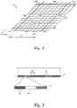
- Fig. 2 shows an exemplary resource grid of resource blocks of the communication channel CH used between the nodes 2 i and the UEs 3 k in the wireless uplink communications 8 as well as in the wireless downlink communications 9.
- the channel CH is subdivided in frequency f into frequency bands FB, each accommodating a subcarrier (not shown), and in time t into time slots ST.
- a combination of a frequency band FB and a time slot ST is called a resource block RB n and carries, e.g., 14 - 224 OFDM symbols SY on 12 subcarriers in 12 frequency bands FB.
- One subcarrier or frequency band FB of one OFDM symbol SY represents a resource element RE of a resource block RB n .
- the entire (uplink or downlink) communication channel CH spans in frequency f over a multitude of resource blocks RB n and in time over a multitude of time slots ST.
- An exemplary frequency range BW of a 5G-NR cellular network for RMR is 10 MHz, accommodating 50 resource blocks RB n with each a frequency band FB of 200 KHz (actually: 180 KHz with a spacing of 20 KHz) .
- each frame F is subdivided into 10 subframes SF, and each subframe SF is comprised of an arbitrary number (actually: a number linked to the subcarrier spacing used) of time slots ST, e.g., 1, 2, 4, 8 or 16 time slots ST.
- Each time slot ST is subdivided into an arbitrary number of OFDM symbols SY, e.g., 14 symbols SY.
- each slot ST of the channel CH can be either used for uplink, i.e. be in the communication mode "uplink” (designated “U"), or used for downlink, i.e. be in the communication mode “downlink” (designated “D").
- Time slots ST designated with "S" in the pattern P i are "special” or “mixed” time slots which a contain a silent or “guard” period GP to account for propagation delays between a node 2 i and a UE 3 k on the channel CH.
- a mixed time slot “S” is used between a downlink time slot “D” and an uplink time slot “U”.
- a mixed time slot “S” may contain downlink symbols SY at the beginning, followed by a short guard period GP and ending with some uplink symbols SY.
- Fig. 4 shows a possible interference scenario that may happen when two adjacent cells (such as the cells 2 1 and 2 2 or the cells 2 2 and 2 3 in Fig. 1 ) have communication channels CH with different patterns P i , P i+1 .
- some of the slots ST of the first pattern P i and some of the slots ST of the second pattern P i+1 are concurrently in the same communication mode D, S or U, see sections T 1 and T 3 of the patterns P i and P i+1 , whereas at other times some of the slots ST of the two patterns P i and P i+1 are in different communication modes, see section T 2 of the patterns P i and P i+1 .
- an uplink communication 8 of a UE 3 k to its node 2 i could severely interfere with a downlink communication 9 received at a neighbouring UE k+1 from the node 2 i+1 , or a downlink communication 9 of a node 2 i+1 to a UE 3 k+1 could severely interfere with an uplink communication 8 of a neighbouring UE 3 k to the node 2 i .
- two adjacent nodes 2 i , 2 i+1 which have differing TDD patterns P i , P i+1 are configured as follows.
- each node 2 i , 2 i+1 uses the full frequency range BW to allocate resource blocks RB n to its connected UEs 3 k , 3 k+1 as needed.
- the first node 2 i uses only a part A and the second mode 2 i+1 uses only a part B (different from part A) of the frequency range BW for allocating resource blocks RB n to its respectively connected UEs 3 k , 3 k+1 as required.
- the unused space of the ressource grid of the channel CH is shown in white in Fig. 5a for the first node 2 i and in Fig. 5b for the second node 2 i+1 .
- Fig. 6 is the combination of Figs. 5a and 5b , showing the combined usage of the resource grid of the channel CH by the nodes 2 i , 2 i+1 in the area of overlap 10 of the cells 7 i , 7 i+1 .
- the parts A and B of the frequency range BW may be separated from one another by a "guard band" GB which is - in frequency f ("height" in Fig. 6 ) - at least one resource block RB n wide.
- a guard band GB of two to six resource blocks RB n in height e.g., four resource blocks RB n in height, may be a good compromise between interference suppression and throughput.
- the two adjacent nodes 2 i , 2 i+1 are sychronised in time so that the beginnings of their respective frames F, and hence the time slots ST, coincide.
- the uplink (“U”), downlink (“D”) and mixed (“S”) time slots ST are arranged in each pattern P i , P i+1 such that the number of time slots ST with differing communication modes that overlap in time between both patterns P i , P i+1 are minimised (in the example of Figs. 4 - 6 : to four such differing time slots ST).
- Minimising the number of time slots ST differing in communication mode (U, D, S) between the two patterns P i , P i+1 is equivalent to minimising the so-called "Levenshtein" distance between the two patterns P i , P i+1 by rearranging the slots ST within each pattern P i , P i+1 .
- the number of time slots ST with differing communication modes that overlap between both patterns P i , P i+1 are optionally made contiguous, see the continuous guard band GB shown in Fig. 6 .
- the number of uplink time slots "U” as well as the number of downlink time slots “D” in the pattern P i of that cell 7 i are usually given.
- the number of mixed time slots "S" necessary for guarding between downlink and uplink time slots "D", "U” follows from the former numbers. Still, by rearranging the order of the of uplink, downlink and mixed time slots "U”, “D”, "S” the number of time slots ST with differing communication modes that overlap in time between the two patterns P i , P i+1 of the adjacent nodes 2 i , 2 i+1 , i.e. their Levenshtein distance, can be minimised.
- a first pattern P 1 in a first cell 7 1 e.g., a suburban area with primarily downlink and hence a lot of downlink time slots "D”
- a target (“third") pattern P 3 in a target (“third") cell 7 3 e.g., an industrial or railway shunting area with a lot of uplink traffic and hence a lot of uplink time slots "U”
- an intermediate node 2 2 for an intermediate cell 7 2 could be established therebetween and configured to mitigate the change from the pattern P 1 to the pattern P 3 via an intermediate pattern P 2 . This is shown in the lower half of Fig. 1 .
- the number of uplink time slots "U”, the number of downlink time slots “D” and the number of mixed time slots “S” in the intermediate (second) pattern P 2 are chosen, and in each pattern P 1 , P 2 , P 3 the uplink, downlink and mixed time slots "U”, "S", “D” are (re-) arranged, such that both of the following two criteria are met:
- the term "substantially equal” may mean equality ⁇ 1 or a broader tolerance window of equality.
- the intermediate pattern P 2 is chosen, and all the time slots in all patterns P 1 , P 2 , P 3 are arranged, such that the number of time slots ST differing in communication mode between the first and the second pattern P 1 , P 2 is less than six (here: four) and the number of time slots ST differing in communication mode between the second and the third pattern P 2 , P 3 is also less than six (here: four).
- Fig. 1 The concept shown in Fig. 1 for three nodes 2 1 - 2s and patterns P 1 - P 3 can, of course, be extended to more than one intermediate node 2 2 and more than one intermediate pattern P 2 between a source pattern P 1 and a target pattern P 3 , to smooth the transition between them.
Landscapes
- Engineering & Computer Science (AREA)
- Signal Processing (AREA)
- Computer Networks & Wireless Communication (AREA)
- Mobile Radio Communication Systems (AREA)
Priority Applications (1)
| Application Number | Priority Date | Filing Date | Title |
|---|---|---|---|
| EP23164993.0A EP4440173A1 (de) | 2023-03-29 | 2023-03-29 | Knotensystem für ein zellulares tdd-netzwerk |
Applications Claiming Priority (1)
| Application Number | Priority Date | Filing Date | Title |
|---|---|---|---|
| EP23164993.0A EP4440173A1 (de) | 2023-03-29 | 2023-03-29 | Knotensystem für ein zellulares tdd-netzwerk |
Publications (1)
| Publication Number | Publication Date |
|---|---|
| EP4440173A1 true EP4440173A1 (de) | 2024-10-02 |
Family
ID=85781789
Family Applications (1)
| Application Number | Title | Priority Date | Filing Date |
|---|---|---|---|
| EP23164993.0A Pending EP4440173A1 (de) | 2023-03-29 | 2023-03-29 | Knotensystem für ein zellulares tdd-netzwerk |
Country Status (1)
| Country | Link |
|---|---|
| EP (1) | EP4440173A1 (de) |
Citations (4)
| Publication number | Priority date | Publication date | Assignee | Title |
|---|---|---|---|---|
| CN102291785A (zh) * | 2011-09-21 | 2011-12-21 | 电信科学技术研究院 | 小区间资源协调的方法和设备 |
| US20130155917A1 (en) * | 2010-09-02 | 2013-06-20 | Zte Corporation | Dynamic sub-frame configuration method and apparatus in time division duplex system |
| WO2013170220A2 (en) * | 2012-05-11 | 2013-11-14 | Qualcomm Incorporated | Interference management for adaptive tdd with frequency domain separations |
| US20140126501A1 (en) * | 2011-04-08 | 2014-05-08 | China Academy Of Telecommunications Technology | Method and device for inter-cell interference coordination |
-
2023
- 2023-03-29 EP EP23164993.0A patent/EP4440173A1/de active Pending
Patent Citations (4)
| Publication number | Priority date | Publication date | Assignee | Title |
|---|---|---|---|---|
| US20130155917A1 (en) * | 2010-09-02 | 2013-06-20 | Zte Corporation | Dynamic sub-frame configuration method and apparatus in time division duplex system |
| US20140126501A1 (en) * | 2011-04-08 | 2014-05-08 | China Academy Of Telecommunications Technology | Method and device for inter-cell interference coordination |
| CN102291785A (zh) * | 2011-09-21 | 2011-12-21 | 电信科学技术研究院 | 小区间资源协调的方法和设备 |
| WO2013170220A2 (en) * | 2012-05-11 | 2013-11-14 | Qualcomm Incorporated | Interference management for adaptive tdd with frequency domain separations |
Non-Patent Citations (1)
| Title |
|---|
| NTT DOCOMO: "Interference Mitigation Schemes for eIMTA", vol. RAN WG1, no. Chicago, USA; 20130415 - 20130419, 16 April 2013 (2013-04-16), XP050697451, Retrieved from the Internet <URL:http://www.3gpp.org/ftp/tsg_ran/WG1_RL1/TSGR1_72b/Docs/> [retrieved on 20130416] * |
Similar Documents
| Publication | Publication Date | Title |
|---|---|---|
| JP7242790B2 (ja) | ディスカバリー信号を伝送する方法および装置、そしてディスカバリー信号を受信する方法および装置 | |
| JP6527530B2 (ja) | 基地局および端末 | |
| US8638652B2 (en) | Signal transmission with fixed subcarrier spacing within OFDMA communication systems | |
| CN101305629B (zh) | 用于不同系统共存的蜂窝通信系统和方法 | |
| CN1984432B (zh) | 分配无线电通信系统的频带上的资源的方法及其相关设备 | |
| KR20100106364A (ko) | 통신 시스템용의 유연한 ofdm/ofdma 프레임 구조 | |
| US20250175316A1 (en) | Latency reduction in tdd systems with carrier aggragation | |
| KR102242515B1 (ko) | 무선 자원 멀티플렉싱 방법, 기지국 장치, 단말기 장치 및 무선 통신 시스템 | |
| JP6380383B2 (ja) | 通信制御装置、通信制御方法、無線通信システム及び端末装置 | |
| WO2014174878A1 (ja) | 通信制御装置、通信制御方法、無線通信システム及び端末装置 | |
| US20140073338A1 (en) | Multicoordination scheduling | |
| CN101262702B (zh) | 一种共享频谱资源的两个时分双工系统融合共存方法 | |
| WO2014174879A1 (ja) | 通信制御装置、通信制御方法、無線通信システム及び端末装置 | |
| JP2014082588A (ja) | 通信システム、基地局装置及び通信方法 | |
| EP4440173A1 (de) | Knotensystem für ein zellulares tdd-netzwerk | |
| EP3487205A1 (de) | Messspaltkonfiguration für 5g | |
| KR101189806B1 (ko) | 자원 할당 방법 및 자원 할당 장치 | |
| KR101076488B1 (ko) | 무선 통신 시스템, 기지국 및 송신 방법 | |
| KR20170121705A (ko) | 디스커버리 신호를 전송하는 방법 및 장치, 그리고 디스커버리 신호를 수신하는 방법 및 장치 | |
| EP3236591A1 (de) | Mobilfunknetz mit linearer zelltopologie, knoten und verfahren dafür | |
| KR20170107386A (ko) | 복수의 뉴머롤로지에 기반한 신호 송수신 방법 및 장치 | |
| CN116388911B (zh) | 一种5gnr接入回传一体化波形设计方法 | |
| JP2011029876A (ja) | 無線通信方法及び無線通信システム | |
| US10117251B2 (en) | Wireless communication system in which one radio access technology operates in conjunction with a second radio access technology | |
| JP6074795B2 (ja) | マルチホップ無線通信システム |
Legal Events
| Date | Code | Title | Description |
|---|---|---|---|
| PUAI | Public reference made under article 153(3) epc to a published international application that has entered the european phase |
Free format text: ORIGINAL CODE: 0009012 |
|
| STAA | Information on the status of an ep patent application or granted ep patent |
Free format text: STATUS: THE APPLICATION HAS BEEN PUBLISHED |
|
| AK | Designated contracting states |
Kind code of ref document: A1 Designated state(s): AL AT BE BG CH CY CZ DE DK EE ES FI FR GB GR HR HU IE IS IT LI LT LU LV MC ME MK MT NL NO PL PT RO RS SE SI SK SM TR |
|
| STAA | Information on the status of an ep patent application or granted ep patent |
Free format text: STATUS: REQUEST FOR EXAMINATION WAS MADE |
|
| 17P | Request for examination filed |
Effective date: 20241028 |
|
| RBV | Designated contracting states (corrected) |
Designated state(s): AL AT BE BG CH CY CZ DE DK EE ES FI FR GB GR HR HU IE IS IT LI LT LU LV MC ME MK MT NL NO PL PT RO RS SE SI SK SM TR |
|
| STAA | Information on the status of an ep patent application or granted ep patent |
Free format text: STATUS: EXAMINATION IS IN PROGRESS |