EP4442111A1 - Tambour hacheur pour une récolteuse-hacheuse - Google Patents
Tambour hacheur pour une récolteuse-hacheuse Download PDFInfo
- Publication number
- EP4442111A1 EP4442111A1 EP24161510.3A EP24161510A EP4442111A1 EP 4442111 A1 EP4442111 A1 EP 4442111A1 EP 24161510 A EP24161510 A EP 24161510A EP 4442111 A1 EP4442111 A1 EP 4442111A1
- Authority
- EP
- European Patent Office
- Prior art keywords
- rotation
- carrier element
- fixing device
- section
- cutting
- Prior art date
- Legal status (The legal status is an assumption and is not a legal conclusion. Google has not performed a legal analysis and makes no representation as to the accuracy of the status listed.)
- Pending
Links
Images





Classifications
-
- A—HUMAN NECESSITIES
- A01—AGRICULTURE; FORESTRY; ANIMAL HUSBANDRY; HUNTING; TRAPPING; FISHING
- A01F—PROCESSING OF HARVESTED PRODUCE; HAY OR STRAW PRESSES; DEVICES FOR STORING AGRICULTURAL OR HORTICULTURAL PRODUCE
- A01F29/00—Cutting apparatus specially adapted for cutting hay, straw or the like
- A01F29/09—Details
- A01F29/095—Mounting or adjusting of knives
-
- A—HUMAN NECESSITIES
- A01—AGRICULTURE; FORESTRY; ANIMAL HUSBANDRY; HUNTING; TRAPPING; FISHING
- A01F—PROCESSING OF HARVESTED PRODUCE; HAY OR STRAW PRESSES; DEVICES FOR STORING AGRICULTURAL OR HORTICULTURAL PRODUCE
- A01F29/00—Cutting apparatus specially adapted for cutting hay, straw or the like
- A01F29/06—Cutting apparatus specially adapted for cutting hay, straw or the like having rotating knives with their cutting edges on a cylinder surface, e.g. of the helical-type
Definitions
- the invention relates to a chopper drum for a forage harvester.
- the chopper drum is designed to rotate in a direction of rotation around an axis of rotation.
- the chopper drum has at least one fixing device.
- the chopper drum has at least one first carrier element.
- a first cutting element with a blade for cutting crops is arranged on the first carrier element.
- the first carrier element is fastened to the fixing device.
- the chopper drum has a second carrier element.
- a second cutting element with a blade for cutting crops is arranged on the second carrier element.
- the second cutting element is arranged adjacent to the first cutting element in the direction of rotation.
- the second carrier element is fastened to the fixing device.
- the second carrier element is also arranged at a distance from the first carrier element in the direction of rotation.
- the chopping drum is basically used to chop up crops. To do this, the chopping drum rotates around the axis of rotation while crops are moved towards it. The cutting elements cut a portion of the crops fed in per cycle.
- the spacing of the carrier elements from one another is of central importance in order to be able to position each cutting element optimally and to prevent the fastening of the carrier elements from being overloaded by forces exerted by a neighboring carrier element.
- a previously described chopping drum is from the DE 697 46 657 T2 , the DE 88 13 953 U1 and the DE 195 22 056 C2 known.
- the carrier elements are placed on flat or outwardly curved surfaces of the fixing device facing away from the axis of rotation and secured by means of a fastening device.
- the fastening device presses the carrier elements onto the fixing device.
- the known chopping drums are disadvantageous because the forces to be transmitted from the carrier elements in the direction of rotation to the fixing device, which are only achieved by pressing, are relatively low and the fastening devices Crop throughputs that require greater forces to be transmitted.
- the fastening elements give way in that they lengthen and allow an unintentionally large distance between the cutting edge and the axis of rotation, which can result in a collision of the cutting edge.
- the object of the present invention is to improve the fastening of the support elements in order to achieve greater crop throughputs.
- the fixing device forms a first engagement recess in a cross-section perpendicular to the axis of rotation.
- the first carrier element has a first engagement section.
- the first engagement section engages in the engagement recess.
- the fixing device is in particular a central part of the chopping drum in relation to the axis of rotation.
- the fixing device is designed in one or more parts. If the fixing device is designed in several parts, the parts are preferably immovable relative to one another and particularly preferably at least partially welded to one another. Preferably, at least one part of the fixing device is designed as a cast part.
- the fixing device preferably has a hollow shaft and/or a solid shaft, the longitudinal axis of which corresponds to the axis of rotation.
- the axis of rotation is a geometric axis, not a physical axis.
- the fixing device extends in cross section, in particular in the direction of rotation, along the carrier elements. In cross section, the fixing device is preferably arcuate or ring-shaped around the axis of rotation. Alternatively, the fixing device is preferably disc-shaped.
- the carrier elements in a first advantageous variant lie directly on the hollow shaft.
- the carrier elements lie on a fixing element or different fixing elements, which in turn is/are arranged on the hollow shaft.
- the at least one fixing element extends in particular in the direction of rotation such that its main direction of extension is the direction of rotation.
- the fixing element is particularly preferably ring-shaped.
- the fixing element lies along its entire extension in the direction of rotation, preferably without gaps, on the hollow shaft.
- the fixing device particularly preferably has a plurality of fixing elements spaced apart from one another in an axial direction parallel to the axis of rotation, against which the first carrier element in particular lies.
- the first carrier element is preferably formed in one piece.
- any fastening means such as screws or rivets are not to be regarded as part of the first carrier element.
- the first carrier element is particularly preferably a drawn or rolled metal profile.
- the first carrier element preferably extends elongated parallel to the cutting edge of the first cutting element.
- the elongated extension is to be understood such that the main extension direction of the carrier element coincides with the extension direction of the cutting edge.
- the main extension direction has an axial and a tangential part in relation to the axis of rotation.
- the length of the first carrier element is in particular at least substantially equal to the length of the first cutting element.
- the length of a contact surface between the first carrier element and the first cutting element preferably corresponds to the length of the first carrier element. This design of the first carrier element achieves extensive support for the first cutting element.
- each cutting element is carried by exactly one carrier element.
- each carrier element preferably carries exactly one Cutting element.
- each cutting element forms a cutting unit with the carrier element carrying the cutting element.
- the position of the second carrier element differs from the position of the first carrier element preferably only by a pivoting about the axis of rotation.
- the first and the second carrier element are therefore spaced apart from one another in the direction of rotation.
- no further carrier element is arranged between the first carrier element and the second carrier element, at least in relation to the direction of rotation.
- the cutting elements are in particular knives.
- the first cutting element and the second cutting element are in particular identical in design.
- the cutting elements are preferably screwed to the respective carrier element.
- no further cutting element is arranged between the first cutting element and the second cutting element in relation to the direction of rotation.
- the cross-sectional area of the cutting elements preferably extends at least in sections partially tangentially and partially radially elongated and ends in their respective cutting edge.
- the blades work together in particular with a counter blade that is immovably arranged relative to the axis of rotation.
- the crop is cut in particular in the manner of a scissor cut between one of the blades and the counter blade.
- the blades define the outer diameter of the chopping drum.
- each point of the blade is at a constant distance from the axis of rotation.
- each point of the blade lies in an imaginary cylindrical surface or conical surface related to the axis of rotation.
- the blade is preferably angled to the axial direction, i.e. not parallel, and/or spiral-shaped around the axis of rotation.
- the first cutting element and the second cutting element belong to a first set of cutting elements which are cut in said cross-section.
- the first set of cutting elements preferably comprises a total of up to 18 cutting elements.
- the The chopping drum preferably has a second set of cutting elements which is arranged offset from the first set in the axial direction.
- the two sets of cutting elements are designed in the same way.
- the second set is particularly preferably mirrored on a mirror plane perpendicular to the axis of rotation and arranged pivoted about the axis of rotation.
- the first engagement recess is preferably open to the outside in cross-section, i.e. at least partially facing away from the axis of rotation (when the fixing device is considered in isolation).
- the first engagement recess in cross-section is particularly preferably a depression in the outer contour of the fixing device.
- the first engagement recess preferably defines a space into which the first engagement section engages in such a way that a straight line, in particular a tangent related to the axis of rotation, intersects the first engagement section in cross-section and a part of the fixing device on either side thereof.
- the first engagement section is in particular only in direct contact with one of the two parts or both parts. The above expressly applies apart from any fastening means.
- a reverse arrangement is also possible, in which the first carrier element forms the first engagement recess into which the fixing device engages with the first engagement section.
- the chopping drum according to the invention is in particular part of a forage harvester and is used therein for shredding crops. Furthermore, the forage harvester has a receiving device for receiving plants as crops and an ejection device for ejecting the shredded crops.
- the first engagement section engages in the first engagement recess in such a way that the first engagement section rests on a part of the fixing device that runs ahead in the direction of rotation and rests on a part of the fixing device that runs behind in the direction of rotation.
- the engagement section rests on the edge of the engagement recess and through which a tangent runs that coincides with the direction of rotation and first intersects the engagement section and then the fixing device.
- the engagement section rests on the edge of the engagement recess and through which a tangent runs in the direction of rotation, which first intersects the fixing device and then the engagement section.
- the parts of the fixing device mentioned are to be understood as locally leading or trailing.
- the engagement section in the engagement recess does not have to lie completely on the edge of the engagement recess, but can also lie only at certain points on the two parts of the fixing device. This design ensures that the first carrier element is positively secured both in the direction of rotation and against the direction of rotation and is therefore suitable for absorbing high forces in these directions.
- the fixing device particularly preferably forms a main bearing against which the first carrier element rests from the outside.
- the fixing device forms a counter bearing that rests on the first carrier element from the outside.
- the bearings are to be understood as parts of the fixing device with which the carrier element preferably has direct contact.
- a gap of up to 0.2 mm can occur between the counter bearing and the first carrier element.
- “Attacking from the outside” means that a radial through the first carrier element and the respective bearing cuts the first carrier element between the counter bearing of the axis of rotation and the main bearing between the first carrier element and the axis of rotation.
- the element that rests from the outside is at least locally further away from the axis of rotation than the other element.
- the first carrier element rests with the engagement section on the main bearing and/or the counter bearing.
- the main bearing and the counter bearing are visible in particular in the same cross section.
- the first carrier element is in particular screwed to the main bearing or against the main bearing.
- the design with the bearings resting on the inside and outside of the first carrier element results in a further improved fixing of the first carrier element to the fixing device.
- the counter bearing makes a screw for fixing the first carrier element to the fixing device unnecessary or in particular supports it.
- the counter bearing is designed as a part of the fixing device that runs forward in the direction of rotation.
- the main bearing is designed in particular as a part of the
- the part of the fixing device running behind the main bearing is designed as a part of the fixing device.
- the first carrier element preferably rests on the counter bearing in cross section with an end pointing at least partially in the direction of rotation.
- the contact surface between the counter bearing and the first carrier element particularly preferably runs partially radially and partially in the direction of rotation in cross section.
- at least part of the main bearing has a larger radius than at least part of the counter bearing. Due to the above-described arrangement of the counter bearing, it counteracts in particular an unintentional rotation of the first carrier element, which could be triggered by an impact of the first cutting element on an obstacle.
- the main bearing rests against the first carrier element in particular with a carrier element contact surface.
- the carrier element contact surface is preferably angled to a radial line intersecting the carrier element contact surface in such a way that the carrier element contact surface approaches the axis of rotation from a first contact surface end in particular to a second contact surface end in the direction of rotation.
- the carrier element contact surface is in particular designed to be straight, with any grooves being disregarded.
- the first carrier element is preferably detachably attached to the fixing device.
- the first carrier element is screwed to the fixing device with at least one screw.
- the screw rotation axis of the screw is arranged in particular at right angles to the carrier element contact surface and/or in an axial plane at right angles to the rotation axis.
- the first carrier element preferably has a first leg and a second leg in cross-section.
- the first cutting element is arranged on the first leg.
- the second leg forms the first engagement section.
- the first leg and the second leg extend at an angle to each other. From a connecting area of the legs, both legs extend in particular at least partially in the direction of rotation. Particularly preferably, the two legs extend at an angle of approximately 90° to each other.
- the first leg is in particular spaced apart from the fixing device.
- the first carrier element preferably does not include parts extending beyond the two mentioned legs.
- both legs have holes for screws. Due to the angled design of the legs, the heads of the screws with which the first carrier element is attached to the fixing device can be arranged between the first cutting element and the fixing device. This results in a smaller installation space requirement for the first carrier element while maintaining the improved stability, whereby a larger number of cutting elements can be distributed over the circumference of the chopping drum.
- the main bearing is arranged in cross-section on a first side of the second leg and the counter bearing is arranged on a side of the second leg opposite the first side.
- the sides In cross-section, the sides have contours in particular that preferably run in a straight line and at least substantially parallel to one another.
- the screw head lies in particular next to the counter bearing on the second side.
- the first leg preferably rests on the outside of the first cutting element in such a way that a radial line in cross-section related to the axis of rotation intersects the first cutting element between the first leg and the axis of rotation. From the cutting edge, the cutting element therefore extends into a space between the first leg and the fixing device. This is in particular the space that is required for inserting the screw through the second leg and into the fixing device before the cutting element is mounted. This design makes it particularly easy to achieve the advantages described above. In addition, there is a larger space between the first cutting element and the axis of rotation in which the crop can be gradually diverted. This results in the chopping drum running more smoothly.
- the first engagement recess in cross-section has a first extension in the direction of rotation at a first radius and a second extension in the direction of rotation at a second radius which is smaller than the first radius, which is greater than the first extension.
- first engagement recess in cross-section increases with increasing distance from the axis of rotation at least in sections becomes narrower. This applies in particular equally to the first engagement section within the first engagement recess.
- There is thus a type of undercut which preferably prevents separation of the first carrier element from the fixing device solely by a translatory relative movement, in particular radial. This further secures the position of the first carrier element.
- the fixing device preferably has a groove which extends oblongly at an angle to the cross-sectional plane and in which a projection of the first carrier element is arranged.
- the groove extends oblongly, in particular parallel to the main direction of extension of the first carrier element and/or the cutting edge.
- the groove is preferably formed in or next to the main bearing.
- the groove is in particular at a greater distance from the axis of rotation than a (wider) part of the engagement recess.
- the groove preferably has a rounded contour which gradually merges into the surfaces of the fixing device surrounding the groove. The groove continues the positive connection and also facilitates the positioning of the first carrier element on the fixing device when assembling the chopping drum.
- the groove is particularly preferably offset from the screw that extends through the first carrier element into the fixing device.
- the groove is offset relative to the screw, in particular towards the axis of rotation. This prevents the groove from endangering the screw connection. In particular, it is avoided that the groove does not extend into the direct pressure area of the screw head.
- the groove is particularly rounded in cross-section in order to avoid notch effects and to protect the screw connection.
- the first cutting element is preferably arranged between the first carrier element, in particular the first leg, and a counter-carrier element.
- the counter-carrier element has a cross-section, in particular a cross-section offset from the previous cross-section, tapering towards the cutting edge of the first cutting element.
- the counter-carrier element has an arcuate guide surface for deflecting cut crops by more than 90°, preferably by more than 120°, particularly preferably by more than 150°, optimally by approximately 180°.
- the guide surface is designed in particular in a C- or U-shape.
- the guide surface preferably adjoins a surface of the cutting element in a flowing manner.
- the guide surface preferably adjoins a first leg of a carrier element running in the direction of rotation or a cover element running in the direction of rotation. This makes it possible to achieve a particularly good crop flow and good crop release after it has been shredded, with only relatively low forces occurring.
- the counter-carrier element preferably lies flat against the surface of the cutting element and, like the first carrier element, extends longitudinally parallel to the cutting edge of the first cutting element.
- the first cutting element is preferably screwed between the counter-carrier element and the first carrier element.
- the counter-carrier element is in particular designed in one piece.
- the counter-support element has limiting sections at its axial ends that protrude relative to the guide surface, particularly in the direction of rotation.
- the limiting sections protrude particularly in the direction of the cutting edge of the first cutting element.
- screw receiving sections preferably also protrude relative to the guide surface, into which screws penetrate for screwing the first cutting element.
- the limiting sections have a further positive influence on the flow of crops.
- the fixing device forms a second engagement recess which is offset in the direction of rotation from the first engagement recess and which is the same as the first engagement recess.
- a second engagement section surrounded by a first cover element engages in the second engagement recess.
- the first cover element has a smaller radial extension relative to the axis of rotation than the first carrier element.
- the first cover element serves to replace another carrier element when longer cutting lengths are intended. Due to the smaller radial extension, the first cover element has a positive effect on the crop flow and reduces wear on the chopping drum.
- the fixing device is protected from the crop.
- the second engagement section preferably resembles the first engagement portion.
- the second engagement recess is preferably arranged adjacent to the first engagement recess in cross section.
- an additional covering element is arranged on the first covering element, which has a guide surface facing away from the axis of rotation.
- the additional covering element extends from the first covering element to a further covering element or a further carrier element, which forms a third engagement section that engages in a third engagement recess of the fixing device.
- the third engagement recess is similar to the first engagement recess and is offset in the direction of rotation from the second engagement recess, in particular arranged adjacent to it.
- the guide surface either borders on the further covering element or the further carrier element or is spaced apart from it by means of a gap. In the case of bordering, the additional covering element supports the further covering element or the further carrier element and thus supports the fixing device. Otherwise, the guide surface further improves the crop flow.
- the first covering element and the second covering element are preferably similar.
- the additional covering element can also be formed in one piece with the covering element.
- the covering element and/or the additional covering element have/have at least one driver which projects axially beyond the adjacent carrier element and which also supports the flow of crop material in the lateral areas.
- the first cover element and/or the further cover element have/have in cross section a cover leg which is similar to the second leg of the first carrier element and has the second or third engagement section.
- they have or have in particular a projection section which is arranged in cross section opposite the second or third engagement section, which projects at least partially from the cover section in the direction of rotation and has a projection surface facing away from the axis of rotation. This preferably adjoins the guide surface of the adjacent counter-carrier element or additional cover element which is arranged offset against the direction of rotation.
- the projection section is similar in particular to a shortened first leg of the first carrier element. The projection section also supports the flow of crops beyond the individual carrier and cover elements.
- the chopping drum according to the invention is preferably manufactured by a method in which the first carrier element and in particular also the cover element for fastening to the fixing device is pivoted about a pivot axis that runs parallel to the main extension direction of the first carrier element.
- the engagement section can be levered into the engagement recess.
- the projection is preferably first inserted as far as possible into the groove and then the inner end of the first carrier element is moved towards the counter bearing.
- the engagement section can be inserted into the undercut in this way.
- first carrier element preferably also to be understood with reference to the second carrier element or all carrier elements.
- first engagement recess or the first engagement section are preferably also to be understood with reference to the second/third engagement recess or section or all engagement recesses or sections.
- Direction, perspective and axis-related information are generally to be understood as relating to the axis of rotation.
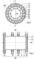
- the figures show different variants of a chopper drum 2 for a field chopper (not shown).
- the chopper drum 2 is designed to rotate in a direction of rotation UR around a rotation axis DA.
- the chopper drums 2 comprise a fixing device 50.
- the fixing device 50 comprises an input shaft 4 and a hollow shaft 6 arranged stationary thereto.
- the fixing device 50 of the first chopping drum 2 comprises four fixing elements 10, 12, 52.
- the fixing elements 10, 12, 52 are essentially ring-shaped and arranged on an outer surface 8 of the hollow shaft 6.
- the fixing elements 10, 12, 52 extend in the direction of rotation UR around the entire circumference of the hollow shaft 6.
- the fixing elements 10, 12, 52 are arranged offset in an axial direction AR on the hollow shaft 6, wherein the axial direction AR is to be understood in relation to the axis of rotation DA.
- a second fixing element 12 is arranged between a first fixing element 10 and further fixing elements 52.
- the second chopping drum 2 according to the invention has two further fixing elements 14, 52, which are designed like the second fixing element 12 and are arranged adjacent to the outer fixing elements 10, 52 on the hollow shaft 6.
- the fixing elements 14, 12, 52 are geometrically identical and are only positioned differently from one another in such a way that they are offset from one another in the axial direction AR and are attached so as to be slightly pivoted relative to one another about the axis of rotation DA.
- the chopping drums 2 each have two similarly designed sets of support elements 16, 18, 19, 56 and cutting elements 20, 24, 27, 70.
- the support elements 16, 18, 19, 56 and the cutting elements 20, 24, 27, 70 are assigned to one another 1:1 and together form cutting units.
- a first of the sets includes a first support element 16, a second support element 18 and a third support element 19 as well as a first cutting element 20, a second cutting element 24 and a third cutting element 27.
- the cutting elements 20, 24, 27 each have a cutting edge 22, 26, 29 which, in the radial view, extends over the first and second fixing elements 10, 12 and in particular the third fixing element 14.
- a second of the sets includes, among other things, a further carrier element 56 and a further cutting element 70 with a cutting edge 72, which extends beyond the other fixing elements 52 in the radial view.
- the sets border in the area of a mirror plane SE in the axial direction AR without touching each other ( Fig. 11 ).
- Each set of the first and second chopping drums 2 according to the invention comprises 18 carrier elements 16, 18, 19, 56 and cutting elements 20, 24, 27.
- each set comprises nine carrier elements 16, 18, 19, 56.
- each set comprises six carrier elements 16, 18, 19, 56.
- the following explanations refer to the first set as an example.
- Each of the chopping drums 2 comprises a first carrier element 16, a second carrier element 18 and a third carrier element 19, which are arranged adjacent to one another in the direction of rotation UR.
- the carrier elements 16, 18, 19 are each releasably screwed to the first fixing element 10, the second fixing element 12 and in particular the third fixing element 14 by means of a screw 28 ( Fig. 16 ).
- the support elements 16, 18, 19 have a bore 30 for each screw 28.
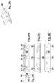
- the support elements 16, 18, 19 have further bores 31 for screws 68 for fixing the cutting elements 20, 24, 27 to the support elements 16, 18, 19 ( Fig. 24a ff.).
- the fixing elements 10, 12, 14 each have a carrier element contact surface 32, 33, 34 for each carrier element 16, 18, 19, against which the respective carrier element 16, 18, 19 rests.
- the carrier element contact surfaces 32, 33, 34 for the first carrier element 16 are arranged offset from one another in the direction of rotation UR.
- the carrier elements 16, 18, 19 and the cutting elements 20, 24, 27 extend longitudinally at an angle to the axial direction AR without having to have a cross section that varies along their length.
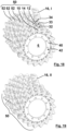
- the carrier element contact surfaces 32, 33, 34 are designed to be angled to an intersecting radial R in a cross section that is perpendicular to the axis of rotation DA ( Fig. 13 ).
- the carrier element contact surfaces 32, 33, 34 approach from a first contact surface end 36 to a second contact surface end 38 at least regardless of a groove 92 of the axis of rotation DA, wherein the second contact surface end 38 is arranged offset in the direction of rotation UR from the first contact surface end 36 ( Fig. 10 ).
- the carrier elements 16, 18, 19 each have an engagement section 82, 83, 84 with which they engage in engagement recesses 79, 80, 81 of the fixing device 50.
- cover elements 64, 65 by which one half or two thirds of the carrier elements 16, 18, 19 are replaced in the third and fourth chopping drum 2 ( Fig. 16 u. 17).
- the fixing device 50 forms a main bearing 87 and a counter bearing 86.
- the support elements 16, 18, 19 have in cross section ( Fig. 10 ) a first leg 44, on which the respective cutting element 20, 24, 27 is arranged, and a second leg 46, which forms the respective engagement section 82, 83, 84.
- the second leg 46 is angled in cross-section to the first leg 44.
- the main bearing 87 rests on a first side 88 of the second leg 46.
- the counter bearing 86 rests on a second side 90 of the second leg 46 ( Fig. 10 ).
- the counter bearing 86 is designed to lead in the direction of rotation UR with respect to the carrier element 16, 18, 19, and the main bearing 87 is designed to trail in the direction of rotation UR.
- the first leg 44 rests from the outside on the cutting element 20, 24, 27 arranged on the carrier element 16, 18, 19 in such a way that the radial R intersects the cutting element 20, 24, 27 between the first leg 44 and the axis of rotation DA.
- the engagement recesses 79, 80, 81 have a first extension U1 in the direction of rotation UR in cross-section at a first radius R1. At a second radius R2, which is smaller than the first radius R1, the engagement recesses 79, 80, 81 have a second extension U2 in the direction of rotation UR, which is greater than the first extension U1 ( Fig. 15 ).
- the carrier elements 16, 18, 19 have a projection 94 which is visible in cross-section and which extends longitudinally, parallel to the cutting edge 22, 26, 29 of the cutting element 20, 24, 27 arranged on the carrier element 16, 18, 19.
- the projection 94 extends into the grooves 92 of the fixing elements 10, 12, 14.
- the groove 92 is arranged offset from the screw 28.
- the cutting elements 20, 24, 27 are each arranged between one of the carrier elements 16, 18, 19 and a counter carrier element 58 ( Fig. 7 ).
- the counter-support element 58 tapers towards the cutting edge 22, 26, 29 of the cutting element 20, 24, 27, against which they rest.
- the counter-support elements 58 have an arcuate guide surface 60 for deflecting cut crop by approximately 180°.
- the counter-support elements 58 have a limiting section 62 protruding at their axial ends relative to the guide surface 60. Between the limiting sections 62, a screw receiving section 63 is arranged for each fixing element 10, 12, 14 ( Fig. 23a ff.).
- the cover elements 64, 65 have a smaller radial extent relative to the axis of rotation DA than the carrier elements 16, 18, 19. Additional cover elements 66 are arranged on the cover elements 64, 65, which have a guide surface 54 facing away from the axis of rotation DA and extend from the respective cover element 64, 65 to the cover element 65 or carrier element 18 advancing in the direction of rotation UR. At least some of the cover elements 64, 65 have a cover leg 67 in cross section, which is similar to the second leg 46 of the carrier elements 16, 18, 19.
- a projection section 69 arranged opposite the second or third engagement section 83, 84 borders the cover leg 67.
- the projection portion 69 protrudes from the cover leg 67 in the direction of rotation UR and has a projection surface 71 facing away from the axis of rotation DA.
- the projection surface 71 adjoins the guide surface 54, 60.
- the chopping drums 2 are manufactured as follows. First, the fixing elements 10, 12, 14 are welded to the outer surface 8 of the hollow shaft 6 ( Fig. 5 ). The fixing elements 10, 12, 14 are then machined ( Fig. 1 to 4 and 6 ). This produces the carrier element contact surfaces 32, 33, 34. In addition, the machining of a torque-absorbing section 40 of the first fixing element 10 produces an input shaft contact surface 42, to which the input shaft 4 is subsequently attached ( Fig. 8 and 11 ). The torque receiving section 40 has a smaller inner diameter than the hollow shaft 6 and is arranged offset in the axial direction AR to the hollow shaft 6. Due to the machining after welding the fixing elements 10, 12, 14, at least apart from the outer fixing elements 10, 52, the fixing elements 12, 14, 52 have an identical raw shape when they are welded ( Fig. 5 ).
- the carrier elements 16, 18, 19 are arranged on the fixing elements 10, 12, 14 after machining.
- the carrier elements 16, 18, 19 are levered with their engagement sections 82, 83, 84 into the engagement recesses 79, 80, 81.
- the carrier elements 16, 18, 19 are moved relative to the fixing device 50 according to five steps I to V and pivoted about a pivot axis SA while resting on the fixing elements 10, 12, 14 ( Fig. 18 - 22 ).
- the projections 94 engage in the grooves 92.
- the pivot axis SA runs parallel to the main direction of extension of the carrier elements 16, 18, 19. After the carrier elements 16, 18, 19 have been levered in, they are fastened, in particular screwed, to the fixing elements 10, 12, 14.
- the cutting elements 20, 24, 27 are then screwed to the carrier elements 16, 18, 19.
- the hollow shaft 6 and the torque absorption section 40 have inner sides extending around the axis of rotation DA, which are shown in the figures in a simplified manner, partly as angular.
- the fixing elements 10, 12, 14, 52 have a complex geometry, which is indicated in particular by lines of lesser thickness. The lines of lesser thickness are not necessarily to be understood as component contours.
Landscapes
- Life Sciences & Earth Sciences (AREA)
- Environmental Sciences (AREA)
- Harvester Elements (AREA)
Applications Claiming Priority (1)
| Application Number | Priority Date | Filing Date | Title |
|---|---|---|---|
| DE102023108775.4A DE102023108775A1 (de) | 2023-04-05 | 2023-04-05 | Häckseltrommel für einen Feldhäcksler |
Publications (1)
| Publication Number | Publication Date |
|---|---|
| EP4442111A1 true EP4442111A1 (fr) | 2024-10-09 |
Family
ID=90362471
Family Applications (1)
| Application Number | Title | Priority Date | Filing Date |
|---|---|---|---|
| EP24161510.3A Pending EP4442111A1 (fr) | 2023-04-05 | 2024-03-05 | Tambour hacheur pour une récolteuse-hacheuse |
Country Status (2)
| Country | Link |
|---|---|
| EP (1) | EP4442111A1 (fr) |
| DE (1) | DE102023108775A1 (fr) |
Citations (6)
| Publication number | Priority date | Publication date | Assignee | Title |
|---|---|---|---|---|
| US4443999A (en) * | 1981-05-09 | 1984-04-24 | Claas Ohg | Chopping cutter of a sugar cane harvester |
| EP0101844B1 (fr) * | 1982-08-20 | 1986-05-28 | Klöckner-Humboldt-Deutz Aktiengesellschaft | Dispositif de hachage pour machine à hacher |
| DE8813953U1 (de) | 1988-11-08 | 1989-01-05 | Claas Ohg, 4834 Harsewinkel | Messertrommel eines Feldhäckslers |
| DE19522056C2 (de) | 1995-06-17 | 1999-06-24 | Case Harvesting Sys Gmbh | Häckseltrommel |
| DE102016112577A1 (de) * | 2016-07-08 | 2018-01-11 | Claas Saulgau Gmbh | Häckseltrommel für einen Feldhäcksler |
| DE102018126694A1 (de) * | 2018-10-25 | 2020-04-30 | Claas Saulgau Gmbh | Häckselmesser einer Häckseltrommel eines Feldhäckslers und Häckseltrommel |
-
2023
- 2023-04-05 DE DE102023108775.4A patent/DE102023108775A1/de active Pending
-
2024
- 2024-03-05 EP EP24161510.3A patent/EP4442111A1/fr active Pending
Patent Citations (6)
| Publication number | Priority date | Publication date | Assignee | Title |
|---|---|---|---|---|
| US4443999A (en) * | 1981-05-09 | 1984-04-24 | Claas Ohg | Chopping cutter of a sugar cane harvester |
| EP0101844B1 (fr) * | 1982-08-20 | 1986-05-28 | Klöckner-Humboldt-Deutz Aktiengesellschaft | Dispositif de hachage pour machine à hacher |
| DE8813953U1 (de) | 1988-11-08 | 1989-01-05 | Claas Ohg, 4834 Harsewinkel | Messertrommel eines Feldhäckslers |
| DE19522056C2 (de) | 1995-06-17 | 1999-06-24 | Case Harvesting Sys Gmbh | Häckseltrommel |
| DE102016112577A1 (de) * | 2016-07-08 | 2018-01-11 | Claas Saulgau Gmbh | Häckseltrommel für einen Feldhäcksler |
| DE102018126694A1 (de) * | 2018-10-25 | 2020-04-30 | Claas Saulgau Gmbh | Häckselmesser einer Häckseltrommel eines Feldhäckslers und Häckseltrommel |
Also Published As
| Publication number | Publication date |
|---|---|
| DE102023108775A1 (de) | 2024-10-10 |
Similar Documents
| Publication | Publication Date | Title |
|---|---|---|
| EP2197613B1 (fr) | Outil rotatif, en particulier foret | |
| DE3624861C2 (fr) | ||
| DE3130828C2 (de) | Werkzeug zum Ausschneiden von Scheiben aus metallischem Material | |
| EP2337649B1 (fr) | Outil à former les filets avec languettes de formage | |
| EP0377060B1 (fr) | Outil de coupe rotatif, en particulier pour la granulation de rubans de matière synthétique | |
| DE69619545T2 (de) | Drehende schneidwerkzeuge | |
| WO2011092000A1 (fr) | Outil d'usinage | |
| DE3831535A1 (de) | Stirnfraeser | |
| EP2848342B1 (fr) | Outil de fraisage complet pour l'usinage rotatif de matériaux | |
| WO2008052503A1 (fr) | Fraise dégrossisseuse et finisseuse | |
| DE69410889T2 (de) | Ein verbesserter frässchneideinsatz | |
| EP3974087A1 (fr) | Outil de fraisage et procédé de fabrication d'un tel outil de fraisage | |
| EP3743234B1 (fr) | Outil de fraisage | |
| EP1980323B1 (fr) | Système de coupe, en particulier pour une machine pour broyage fin | |
| DE3605517A1 (de) | Kreissaegeanordnung | |
| EP2212041B1 (fr) | Système d'outil, notamment de rainurage | |
| EP1579937B1 (fr) | Lame d'ébavurage pour le chanfreinage des trous | |
| EP4442111A1 (fr) | Tambour hacheur pour une récolteuse-hacheuse | |
| EP3463731B1 (fr) | Plaquette de coupe pour un outil de fraisage et outil de fraisage | |
| DE60204391T2 (de) | Einsatz für Kugelfräser mit gezahnter Schneidkante | |
| WO1988004970A1 (fr) | Tete de scie circulaire | |
| EP2311568B1 (fr) | Ensemble de coupe doté d'un compteur de bague d'écartement de sécurité | |
| DE4431960C1 (de) | Messer für Fleischwölfe | |
| EP3795316B1 (fr) | Tête d'outil d'un outil d'usinage | |
| EP1247443B1 (fr) | Dispositif de hachage |
Legal Events
| Date | Code | Title | Description |
|---|---|---|---|
| PUAI | Public reference made under article 153(3) epc to a published international application that has entered the european phase |
Free format text: ORIGINAL CODE: 0009012 |
|
| STAA | Information on the status of an ep patent application or granted ep patent |
Free format text: STATUS: THE APPLICATION HAS BEEN PUBLISHED |
|
| AK | Designated contracting states |
Kind code of ref document: A1 Designated state(s): AL AT BE BG CH CY CZ DE DK EE ES FI FR GB GR HR HU IE IS IT LI LT LU LV MC ME MK MT NL NO PL PT RO RS SE SI SK SM TR |
|
| P01 | Opt-out of the competence of the unified patent court (upc) registered |
Free format text: CASE NUMBER: APP_64190/2024 Effective date: 20241204 |
|
| STAA | Information on the status of an ep patent application or granted ep patent |
Free format text: STATUS: REQUEST FOR EXAMINATION WAS MADE |
|
| 17P | Request for examination filed |
Effective date: 20250408 |