EP4442155A1 - Haartrockner - Google Patents
Haartrockner Download PDFInfo
- Publication number
- EP4442155A1 EP4442155A1 EP21967356.3A EP21967356A EP4442155A1 EP 4442155 A1 EP4442155 A1 EP 4442155A1 EP 21967356 A EP21967356 A EP 21967356A EP 4442155 A1 EP4442155 A1 EP 4442155A1
- Authority
- EP
- European Patent Office
- Prior art keywords
- hairdryer
- heater
- heater module
- air guide
- body housing
- Prior art date
- Legal status (The legal status is an assumption and is not a legal conclusion. Google has not performed a legal analysis and makes no representation as to the accuracy of the status listed.)
- Granted
Links
Images




Classifications
-
- A—HUMAN NECESSITIES
- A45—HAND OR TRAVELLING ARTICLES
- A45D—HAIRDRESSING OR SHAVING EQUIPMENT; EQUIPMENT FOR COSMETICS OR COSMETIC TREATMENTS, e.g. FOR MANICURING OR PEDICURING
- A45D20/00—Hair drying devices; Accessories therefor
- A45D20/04—Hot-air producers
- A45D20/08—Hot-air producers heated electrically
- A45D20/10—Hand-held drying devices, e.g. air douches
- A45D20/12—Details thereof or accessories therefor, e.g. nozzles, stands
-
- A—HUMAN NECESSITIES
- A45—HAND OR TRAVELLING ARTICLES
- A45D—HAIRDRESSING OR SHAVING EQUIPMENT; EQUIPMENT FOR COSMETICS OR COSMETIC TREATMENTS, e.g. FOR MANICURING OR PEDICURING
- A45D20/00—Hair drying devices; Accessories therefor
- A45D20/04—Hot-air producers
- A45D20/08—Hot-air producers heated electrically
- A45D20/10—Hand-held drying devices, e.g. air douches
-
- A—HUMAN NECESSITIES
- A45—HAND OR TRAVELLING ARTICLES
- A45D—HAIRDRESSING OR SHAVING EQUIPMENT; EQUIPMENT FOR COSMETICS OR COSMETIC TREATMENTS, e.g. FOR MANICURING OR PEDICURING
- A45D2200/00—Details not otherwise provided for in A45D
- A45D2200/20—Additional enhancing means
- A45D2200/202—Ionisation
Definitions
- the present disclosure relates to a hairdryer.
- a hairdryer configured to discharge gas through a gas discharge port may be used.
- the hairdryer may be provided therein with a fan unit and the like configured to cause gas to flow.
- the hairdryer including the internal components may be designed for a user to be able to conveniently use the same in consideration of the weight thereof.
- the hairdryer In order to use the hairdryer without wires, the hairdryer must include a battery built therein and must assure an additional space in which the battery is mounted. There is need for a hairdryer which is additionally provided with components such as an ion generator and to which accessories are coupled for the purpose of function enhancement.
- the hairdryer is used in the state of being gripped by a user hand, it is necessary to optimally dispose components in order to prevent the hairdryer from being overly enlarged.
- An object of the present disclosure is to provide a hair dryer including an air guide capable of preventing the heat generated by a heater from being directly transmitted to the outside of a housing.
- the present disclosure provides a hairdryer including a cylindrical body housing including gas discharge portion at a front surface thereof, a body assembly which is inserted into the cylindrical body housing from a rear surface of the body housing, and a handle housing connected to a lower portion of the body housing, wherein the body assembly includes a heater module comprising a cylindrical first heater case and a heating wire wound around an outer circumferential surface of the first heater case, and an air guide surrounding an outer circumferential surface of the heater module and configured to guide air having passed through the heater module to the gas discharge portion, and wherein the air guide includes an insulation material configured to prevent heat generated by the heater module from being transmitted to the body housing.
- the air guide may include a cylindrical member having a length equal to or greater than a length of the heater module and a diameter equal to or larger than a diameter of the heater module.
- the air guide may be a cylindrical member which gradually decreases in diameter with decreasing distance from the gas discharge portion.
- the body assembly may include a board frame which is positioned at a second side of the heater module and to which a main board is mounted, the board frame comprising a first fastener, and the air guide may include a second fastener which extends from a second side and is coupled to the first fastener of the board frame.
- the second fastener may include a hook configured to be fastened to the first fastener, and two or more extension bridges which extend to the hook from the second side of the air guide.
- the body assembly may include a rear cover configured to cover the rear surface of the body housing, and the rear cover may further include a third fastener configured to be fastened to the board frame.
- the hairdryer may further include a user input portion mounted to the rear cover.
- the air guide may include a curved inner surface connected to the air discharge portion.
- the heater module may include a second cylindrical heater case covering an outer circumferential surface of the heating wire, and the second heater case may be in contact with an inner surface of the air guide.
- the first heater case may include a cylindrical lateral surface portion, a front surface portion facing the gas discharge portion of the lateral surface portion, and a rear surface portion positioned opposed to the front surface portion, and the hairdryer may include at least one of a front board or an ion generator positioned inside the first heater case.
- the heater module may be positioned in front of the connecting portion of the handle housing.
- the hairdryer may further include a gas introduction port formed in a lower portion of the handle part, and a blower fan mounted to the handle housing so as to supply air introduced through the gas introduction port to the heater module of the body housing.
- the embodiments of the present disclosure are able to prevent the heat generated by the heater from being transmitted to the outside of the body housing and thus to reduce a risk of burn injury of a user in use.
- the embodiments of the present disclosure are able to improve the availability of a space by efficiently disposing the heater module in the internal space.
- the embodiments of the present disclosure are able to prevent metal components of the main discharge port from being overheated and thus to lower a risk of burn injury.
- the embodiments of the present disclosure are able to prevent damage to components positioned inside the heater module because the heat generated by the heater module is not transmitted inwards in the direction of the first heater case.
- 'and/or' includes a combination of a plurality of listed items or one of the plurality of listed items.
- 'A or B' may include 'A', 'B', or 'both A and B'.
- FIG. 1 illustrates a hairdryer 10 according to an embodiment of the present disclosure.
- FIG. 2 illustrates the cross-section of the interior of the hairdryer 10 shown in FIG. 1 .
- the hairdryer 10 includes a body part 100 and a handle part 200.
- the body part 100 includes an gas discharge portion 120 through which air introduced from the outside is discharged.
- the body part 100 may have formed therein an air passage 150 through which gas flows.
- the gas passage 150 may extend to the inside of the body part 100 from the handle part 200.
- the gas passage 150 may be formed by the inside of the body part 100 and the inside of the handle part 200, and may be defined as a region which extends to the gas discharge portion 120 from the air introduction portion 215.
- the body part 100 may include the gas discharge portion 120 through which the air flowing in the gas passage 150 is discharged to the outside.
- the body part 100 may have a shape which extends parallel to a direction in which air is discharged from the gas discharge portion 120, and may have various cross-sectional shapes such as circular shape and a polygonal shape.
- the air flowing in the body part 100 is introduced through the air introduction portion 215.
- the air introduction portion 215 may be provided at the body part 100 or the handle part 200.
- the air passage 150 may extend to the body part 100 from the handle part 200.
- the air passage 150 may extend to the gas discharge portion 120 from the air introduction portion 215.
- Gas may be introduced from the outside through the air introduction portion 215 provided at the body part 100 or the handle part 200.
- the air introduced through the air introduction portion 215 may flow through the gas passage 150 and may then be discharged to the outside through the gas discharge portion 120 provided at the body part 100.
- the handle part 200 may extend from the body part 100. Referring to FIGs. 1 and 2 , there is shown the handle part 200 which extends approximately downwards from the body part 100.
- the handle part 200 may have a shape which extends from the body part 100.
- the handle part 200 may be molded integrally with or separately from the body part 100, and may be coupled to the body part 100.
- the length or the direction of the handle part 200 with respect to the body part 100 may be constant or variable.
- the handle part 200 may be coupled to the body part 100 via a hinge coupler such that the direction in which the handle part 200 extends is variable.
- the handle part 200 may be constructed so as to be bent with respect to the body part 100.
- the handle part 200 may be a portion which is gripped by a user. Accordingly, the handle part 200 may have such a shape as to improve grip convenience. Although the direction in which the handle part 200 extends may be variously changed, the direction in which the handle part 200 extends from the body part 100 may be referred to as a downward direction for convenience of explanation.
- the up-and-down direction in the present disclosure may be defined based on the handle part 200.
- the handle part 200 may have a shape which extends downwards from the body part 100, and the body part 100 may be positioned above the handle part 200.
- the up-and-down direction in the present disclosure should not necessarily be understood as a direction perpendicular to the ground, and may include an inclined direction as shown in FIG. 2 .
- the up-and-down direction may be defined based on the longitudinal direction of the handle part 200.
- the hairdryer 10 may include a fan unit 250 configured to cause gas to flow and to control velocity of gas discharged through the gas discharge portion 120.
- the fan unit 250 may be disposed in the gas passage 150 so as to cause gas to flow, and may be disposed in the inside of the body part 100 or the inside of the handle part 200.
- the gas passage 150 may extend to the gas discharge portion 120 of the body part 100 from the gas introduction portion 215 of the handle part 200, and the fan unit 250 may be disposed in the gas passage 150 positioned at the handle part 200.
- the hairdryer 10 may include a battery module 240 in order to be wirelessly usable.
- the battery module 240 When the battery module 240 is disposed at the body part 100, the weight of the body part 100 may be increased, and convenience of use is thus deteriorated. Accordingly, the battery module 240 may be disposed at the handle part 200, as illustrated in FIG. 2 . Because the weight of the battery module 240 is greater than the fan unit 250 disposed at the handle part 200, the battery module 240 may be positioned at the lower portion of the handle part 200, and the fan unit 250 may be positioned at the upper portion of the handle part 200.
- the body part 100 may be provided therein with a heater module 160 capable of controlling the temperature of discharged gas.
- the heater module 160 may be constructed so as to have various forms, and may be provided at various positions.
- FIG. 2 schematically illustrates the heater module 160 provided in the body part 100.
- the heater module 160 may be of various kinds.
- the heater module 150 may be operated such a manner as to supply current to a coil-shaped resistor to generate heat and thus to heat gas.
- the heater module may not necessarily have a coil-shaped resistor, and may be any one of various kinds of heater modules which include, for example, a thermoelectric element capable of controlling temperature of gas.
- a user may manipulate a power button disposed at the body part 100 or the handle part 200.
- the power button When the power button is turned on, the fan unit 250 is activated such that gas is introduced into the hairdryer 10 through the gas introduction portion 215.
- the gas introduced through the gas introduction portion 215 flows toward the gas discharge portion 120 along the gas passage 150 by means of the fan unit 250, and is then discharged to the user through the gas discharge portion 120.
- the gas in the gas passage 150 may be controlled in flow rate by means of the fan unit 250, and may be controlled in temperature by means of the heater module 160.
- the hairdryer 10 may include controller 130.
- the controller 130 may be connected to the fan unit 250, the heater module 160, the power button, an operation board and the like so as to control the components.
- the operation of the fan unit 250 and the heater module 160 may be conducted by user manipulation of the operation board, or may be automatically conducted according to an operation mode which is previously set in the controller 130.
- the gas introduction portion 215 may have a plurality of gas introduction holes formed through a handle case 210.
- the gas passage 150 may extend to the gas discharge portion 120 from the gas introduction portion 215 to allow gas to flow therethrough.
- the gas passage 150 may include a second passage 154 and 155, which is positioned at the body part 100, a first passage 151, 152 and 153, which is positioned at the handle part 200 and extends in the longitudinal direction of the handle part 200.
- the gas introduction portion 215 may be positioned at the lower portion of the handle part 200, and the gas discharge portion 120 may be positioned at the end of the body part 100 opposed to the portion of the body part 100 to which the handle part 200 is coupled.
- the gas passage 150 may be constructed such that the first passage 151, 152 and 153 and the second passage 154 and 155 are disposed in an L-shaped arrangement, and may include a pressure compensation passage 153 and 154 in order to prevent flow rate from being reduced at the bent portion of the gas passage 150.
- the pressure compensation passage 153 and 154 is characterized by having a sufficient space or a gentle slope and by being changed in flow direction.
- the pressure compensation passage 153 and 154 is characterized by having a large space.
- the fan unit 250 may be provided in the handle part 200 so as to cause the gas, introduced into the handle part 200, to flow toward the gas discharge portion 120.
- the fan unit 250 may be disposed in the gas passage 150 so as to cause the gas to flow.
- a conventional hairdryer 10 includes the fan unit 250 having a relatively large fan because the fan unit 250 is positioned at the body part 100.
- the fan unit 250 according to the embodiment of the present disclosure is positioned at the handle part 200 and the diameter of the handle part 200 is smaller than the diameter of the body part 100, the size of the fan unit 250 is accordingly reduced.
- the voltage is lower in the case in which the battery module 240 is used than the case in which a wired power source is connected.
- a DC power source of 10 V is used in the wireless case whereas An AC power source of 215 V is used in the wired case.
- the battery module 240 Because the battery module 240 generates heat, it is possible to cool the battery module 240 by disposing the battery module 240 at the gas passage 150. Because the battery module 240 is positioned at the handle part 200, the battery module 240 may be positioned at the first passage disposed in the handle part.
- the first passage 151, 152 and 153 may include a lower passage 151 which is connected to the gas introduction portion 215 and at which the battery module 240 is positioned, and an upper passage 152 at which the fan unit 250 is positioned and which is formed through the fan unit 250.
- the direction in which gas is discharge is defined as a forward direction, and the opposite direction is defined as a rearward direction.
- the following description will be given based on the case in which the gas discharge portion 120 is provided at the front side of the body part 100 and the longitudinal direction of the body 100 is parallel to the forward/backward direction.
- FIG. 3 is a cross-sectional view of the body part 100 of the hairdryer 10 according to an embodiment of the present disclosure.
- FIG. 4 is an exploded perspective view of the hairdryer 10 according to an embodiment of the present disclosure.
- FIG. 5 is a view illustrating a body assembly 105 mounted in the handle part according to the present disclosure.
- the body part 100 may include the heater module 160, the controller 130 configured to control the hairdryer 10, and the user input portion 140.
- the body part 100 may include a cylindrical body housing 110.
- the body part 100 may be provided at the front surface thereof with a main discharge port 125 and at the rear surface thereof with the user input portion 140.
- the heater module 160, the controller 130, and the user input portion 140 may be assembled with one another so as to constitute the body assembly 105.
- the body assembly 105 may be inserted into the body housing 100 in the direction of the front surface from the rear surface of the body housing 110, thereby constituting the body part 100.
- the diameter of the front surface of the body housing 100 may be equal to the diameter of the rear surface of the body housing 110, or may be slightly smaller than the diameter of the rear surface of the body housing 110, as illustrated in FIG. 3 .
- a connecting frame 115 which overlaps the handle case may extend downwards from the body part 100.
- the portion of the body housing 110 at which the connecting frame is formed may be open so as to allow the passage in the handle part 200 to communicate with the passage in the body part 100.
- the heater module 160 may be positioned at the front side whereas the controller 130 and the user input portion 140 are may be positioned at the rear side.
- the vertical airflow in the handle part 200 may be changed into a forward airflow in the space between the heater module 160 and the controller 130.
- the heater module 160 may include a heating wire 161 wound around a cylindrical housing.
- the housing may include a first heater case 165 positioned inside the heating wire 161 and a second heater case 166 positioned outside the heating wire 161.
- the doughnut-shaped space defined between the first heater case 165 and the second heater case 166 may serve as a heating passage 155, and the heating wire 161 may be disposed in the space between the first heater case 165 and the second heater case 166.
- the heating wire 161 may be wound around the first heater case 165 in a circular shape, and may be wound plural turns so as to form a coil shape.
- the diameter of the heating wire 161 wound around the housing may vary as illustrated in FIG. 3 .
- the air flowing through the heating passage 155 defined between the first heater case 165 and the second heater case 166 may come into sufficient contact with the heating wire 161.
- the hairdryer may further include plates for heating wire 161 which radially extend toward the second heater case 166 from the first heater case 165.
- Each of the plates for the heating wire 161 may have grooves in which the heating wire 161 is seated. The grooves may be positioned at different distances from the center of the heater housing.
- the temperature may be increased.
- the heating wire 161 may be burn out when the resistance of the heating wire 161 is low in the case in which AC power source of high voltage is applied, the heating wire 161 may be composed of a coil-shaped heating wire having a small diameter.
- a coil-shaped heating wire 161 which defines a tube having a diameter ranging from 2 to 5 mm may be wound around the first heater case 165 so as to realize the heating wire 161. As heat is generated by the heating wire 161, the temperature of the air flowing through the heating passage 155 may be increased, thereby providing high temperature air.
- the heating wire 161 having this structure may be disposed adjacent to the outer circumferential surface of the body housing 110, and the heat generated by the heating wire 161 may be transmitted to the body housing 110, thereby raising the temperature of the body housing 110. Because the body housing 110, which defines the appearance of the hairdryer 10, may come into direct contact with a user, there is a risk of burn injury when the temperature of the body housing 110 increases to a high temperature.
- a heat insulation structure configured to block the heat generated by the heating wire 161 to prevent the heat from being transmitted to the body housing 110.
- a heat insulation structure may be realized using mica or the like.
- a heat insulation material may be used as the material of the second heater case 166.
- the second heater case 1 defines the heating passage 155, there is a problem in that the efficiency of temperature rise of the air flowing through the heating passage 155 is lowered when the temperature of the second heater case 166 is low.
- an air guide 112 configured to guide air to the gas discharge portion 120 from the heater may be provided so as to surround the heater.
- the air guide 112 may include an insulation material or a heat insulation material such as mica, and may prevent the heat generated by the heating wire 161 from being transmitted to the body housing 110.
- the air guide 112 may include a curved surface connected between the front end of the heater and the gas discharge portion 120, and may extend rearwards to surround the heater for heat insulation.
- the air guide 112 may have a length greater than the longitudinal length of the heater module 160 so as to cover the heater module 160, and may be composed of a cylindrical member having a diameter equal to or larger than the diameter of the heater module 160.
- the gas discharge portion 120 may be disposed at the front surface of the air guide 112, and the heater module 160 may be inserted into the enlarged portion of the air guide 112.
- the air guide 112 may have a cylindrical form the diameter of which also decreases in the direction of the front surface thereof adj acent to the gas discharge portion 120.
- the air guide 112 may be fastened to a board frame 114 to which the main board of the controller 130 is mounted, and may be coupled to a rear cover 116 to which the user input portion 140 of the board frame 114 is seated and which defines the rear surface of the body housing 110.
- the air guide 112, the board frame 114, and the rear cover 116 may be coupled to one another so as to constitute the body assembly 105. Furthermore, the heater module 160 mounted to the air guide 112, the main board coupled to the board frame 114, and the user input portion 140 mounted to the rear cover 116 may also constitute the body assembly 105.
- FIG. 6 is a view illustrating the air guide 112 and the board frame 114 of the hairdryer 10 according to an embodiment of the present disclosure.
- the board frame 114 to which the main board 130 is mounted may be composed of a ring-shaped member, as illustrated in FIG. 6 .
- the air guide 112 may include a second fastener 1125 which is to be coupled to the first fastener 114h of the board frame 114.
- the first fastener and the second fastener may be embodied as a hook and a hook groove, and may each include a plurality of ones arranged therearound, as illustrated in FIG. 6 .
- the connecting frame 115 may be positioned between the heater module 160 and the main board 130.
- the heater module 160 should be spaced apart from the main board 130 such that the air introduced from the handle part 200 flows toward the heater. Accordingly, the second fastener of the air guide 112 may have an elongated shape, as illustrated in FIG. 6 .
- the second fastener 1125 may include a hook 1121 which is coupled to the first fastener 114h and an extension bridge 1122 which extends from the air guide 112. Because there may be a problem in rigidity of the second fastener 1125 when the extension bridge 1122 extends long, the extension bridge 1122 may include two or more extension bridges 1122 to stably fix the hook 1121 to the first fastener 114h.
- the extension bridge 1122 may extend from the hook 1121 to define a predetermined angle such that the second fastener 1125 has a triangular shape.
- the rear cover 116 may include a third fastener to be fastened to the board fastener.
- the rear cover 116 may be exposed to the outside of the hairdryer 10.
- the rear surface of the rear cover 116 may be provided with a touch input portion so as to control the hairdryer 10, and may also include a display configured to display icons configured to guide control of the hairdryer 10 or corresponding to the user input portion 140.
- the gas discharge portion 120 may include a main discharge port 125 having a size smaller than the size of the heating passage 155 in order to discharge the air passing through the heating passage 155 at high velocity.
- the gas discharge portion 120 may include a discharge cover 121, 122 and 124.
- the discharge cover 121, 122 and 124 may have a curved surface to efficiently diffuse the air.
- the ring-shaped main discharge port 125 connected to the heating passage 155 may have a ring shape smaller than the heating passage 155.
- the main discharge port 125 may have a cone-shaped inner surface to guide diffusion of the air discharged from the main discharge port 125, and may include a first ring cover 124 positioned around the outer periphery thereof.
- the air guide 112 may have a curved surface connected between the heater module 160 and the main discharge port 125, as illustrated in FIG. 10 .
- the first ring cover 124 may cover the front surface of the air guide 112 to define the appearance of the hairdryer 10.
- the discharge cover 121, 122 and 124 may be coupled to the front surface of the air guide 112 to constitute one component of the body assembly 105.
- the assembly shown in FIG. 5 in which the air guide 112, the board frame and the rear cover 116 are coupled to one another may be inserted the body housing 110 so as to constitute the body part 100, as illustrated in FIG. 3 .
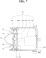
- FIG. 7 is a cross-sectional view of the first heater case 165 of the hairdryer 10 according to an embodiment of the present disclosure.
- FIGs. 8 and 9 are exploded perspective views of the first heater case 165 according to an embodiment of the present disclosure.
- the first heater case 165 which is a cylindrical member, is provided with the heating wire 161 positioned on the outer circumferential surface thereof but is not provided in the internal space thereof with the heating wire 161, other components may be disposed in the internal space of the first heater case 165.
- the first heater case 165 having a cylindrical shape may be composed of at least two pieces so as to open the inside, as illustrated in FIGs. 8 and 9 .
- the first heater case 165 may include a cylindrical lateral surface portion 1651, a front surface portion 1653 positioned at the front surface of the lateral surface portion 1651, and a rear surface portion 1652 positioned at the rear surface of the lateral surface portion 1651.
- the front surface portion 1653 and the rear surface portion 1652 may cover the two ends of the cylindrical lateral surface portion 1651 to define the internal space.
- the present disclosure discloses an embodiment in which the front surface portion 1653 is separated from the lateral surface portion 1651 and the rear surface portion 1652 is formed with the lateral surface portion 1651 and in which the front surface portion 1653 and the rear surface portion 1652 may be fastened by means of a fastener such as a screw.
- a fastener such as a screw.
- the front surface portion 1653 may include a fastener 1653a which projects toward the rear surface portion 1652, as illustrated in FIG. 8 .
- a screw may be inserted forwards into a screw hole 1652a in the rear surface of the rear surface portion 1652 and may then be fastened to the projecting fastener 1653a of the front surface portion 1653.
- the lateral surface portion 1651 may have formed therein a groove at a location corresponding to the projecting fastener 1653a so as to maintain the position of the projecting fastener 1653a and to fix the front surface portion 1653 without rotation relative to the lateral surface portion 1651.
- the hairdryer 10 may include a front board 135 as a representative example.
- the front board 135 may be connected to the components positioned on the front surface of the hairdryer 10 and may be connected to the main board.
- the rear surface portion 1652 may be provided therethrough with a cable hole 1652b so as to allow a cable connected to the main board to pass therethrough.
- the front surface portion 1653 may further include a hook 1653b configured to hold the front board 135.
- any of a temperature sensor positioned on the front surface of the hairdryer 10 and accessories coupled to the front surface of the body housing 100 require supply of power, power may be supplied to the component so as to connect the component to the main board for control.
- a rotating brush or an LED diffuser equipped with an LED module for scalp care may be coupled to the body housing, thereby enabling upgrade of the hairdryer to a multipurpose hairdryer 10 capable of performing hair care while drying hair.
- the discharge cover 121, 122 and 124 of the gas discharge portion 120 of the hair dryer 10 may be used as an electrode.
- the discharge cover 121, 122 and 124 may be made of a conductive metal material and may be connected to the front board 135 such that the cone cover 121 and the first ring cover 124 of the discharge cover 121, 122 and 124 may be used as electrodes.
- the second ring cover 122 adjacent to the periphery of the cone cover 121 may further be provided, and the cone cover 121 and the second ring cover 122 may be used as electrodes. Because the cone cover 121 and the second ring cover 122 are coupled to the front surface of the first heater case 165, the cone cover 121 and the second ring cover 122 are easily connected to the front board 135 mounted in the first heater case 165.
- the accessary When an accessary such as an LED diffuser is coupled to the front surface of the body housing 110, the accessary may be connected to the controller 130 via the discharge cover 121, 122 and 124 such that the accessary coupled to the front surface of the housing is controlled and driven by the controller 130 of the hairdryer 10.
- the temperature sensor may be positioned at the gas discharge portion 120 and may be connected to the front board 135 in order to measure temperature of the air discharged from the heater module 160.
- a temperature measurement portion may be positioned on the outer surface in order to measure temperature of the upper passage, and an electrode configured to connect the temperature sensor to the front board 135 may be connected to the outside through the first heater case 165.
- a signal wire connected to the front board 135 may extend through an opening formed through the front surface portion 1653 of the first heater case 165, and the outer surface of the front surface portion 1653 may have formed therein a groove in which the signal wire is positioned.
- An ion generator 136 may further be provided in the first heater case 165.
- the ion generator 136 is a device configured to create negative ions which have effects of sterilization, cellular activation and odor removal. Furthermore, the negative ions have effects of prevention of static electricity and of improving hair texture by smoothly arranging cuticles of the hair.
- the negative ions created by the ion generator 136 are supplied through a negative ion brush or a negative ion pin 1365, it is possible to supply the negative ions created by the ion generator 136 in the direction of the heating passage 155 through the outer surface of the first heater case 165.
- the temperature of the first heater case 165 increases due to the heating wire 161 positioned at the periphery of the first heater case 165 and thus the temperature of the internal space of the first heater case 165 also increases.
- the temperature of the internal space of the first heater case 165 increases, there is the concern that electronic components such as the front board 135 and the ion generator 136 which are positioned inside the first heater case 165 are damaged due to high heat.
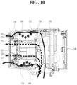
- FIG. 10 is a cross-sectional view illustrating the heating passage 155 and the subsidiary passage 156 of the hairdryer 10 according to an embodiment of the present disclosure.
- the rear surface portion 1652 of the first heater case 165 may be closed in order to guide the air between the first heater case 165 and the second heater case 166.
- a plurality of vent holes 1655 may be formed along the periphery of the rear surface portion 1652. Some of the air supplied from the first passage may be introduced into the inside of the first heater case 165 through the vent holes 1655.
- the temperature of the air supplied from the first passage is not high, it is possible to obtain an effect of lowering the temperature of the first heater case 165.
- the plurality of vent holes 1655 may be formed along the periphery of the rear surface portion 1652 so as to allow the air to flow along the inner surface of the first heater case 165.
- the size of the vent holes 1655 is overly large, the amount of air supplied to the heating passage 155, which is the main passage, is reduced. Accordingly, the size of the subsidiary passage 156 may be smaller than the size of heating passage 155.
- the air having passed through the vent holes 1655 may flow along the inner surface of the first heater case 165, and may then be discharged through the opening formed through the periphery of the front surface portion 126.
- the discharge cover 121, 122 and 124 may further include the second ring cover 122 positioned around the cone cover 121.
- the subsidiary discharge port 126 may be positioned between the second ring cover 122 and the cone cover 121 so as to allow the air having passed through the subsidiary passage 156 to be discharged.
- the brush or pin 1365 of the ion generator 136 may be positioned in the first heater case 165 without having to extend to the outside of the first heater case 165.
- a heat insulation tube 169 including an insulation material may further be provided in the first heater case 165. Consequently, transmission of heat to the inside of the first heater case 165 is prevented, thereby making it possible to prevent rise of the internal temperature of the first heater case 165 while increasing an amount of heat supplied to the air passing through the heating passage 155.
- the air passing through the subsidiary passage 156 has effects not only of protecting the internal components of the first heater case 165 but also of lowering the temperature of the discharge cover 121, 122 and 124 because the air passes through the discharge cover 121, 122 and 124. Because the discharge cover 121, 122 and 124 is also exposed to the outside, there is a risk of burn injury. Accordingly, it is possible to lower the temperature of the discharge cover 121, 122 and 124 using low temperature air in the subsidiary passage 156.
- the embodiments of the present disclosure are able to prevent the heat generated by the heater from being transmitted to the outside of the body housing 110 and thus to reduce a risk of burn injury of a user in use.
- the embodiments of the present disclosure are able to improve the availability of a space by efficiently disposing the heater module 160 in the internal space.
- the embodiments of the present disclosure are able to prevent metal components of the main discharge port 125 from overheating, thus lowering the risk of burn injury.
- the embodiments of the present disclosure are able to prevent damage to components positioned inside the heater module 160 because the heat generated by the heater module 160 is not transmitted inwards in the direction of the first heater case 165.
Landscapes
- Cleaning And Drying Hair (AREA)
Applications Claiming Priority (2)
| Application Number | Priority Date | Filing Date | Title |
|---|---|---|---|
| KR1020210176693A KR102585495B1 (ko) | 2021-12-10 | 2021-12-10 | 헤어드라이어 |
| PCT/KR2021/018850 WO2023106483A1 (ko) | 2021-12-10 | 2021-12-13 | 헤어드라이어 |
Publications (3)
| Publication Number | Publication Date |
|---|---|
| EP4442155A1 true EP4442155A1 (de) | 2024-10-09 |
| EP4442155A4 EP4442155A4 (de) | 2025-03-05 |
| EP4442155B1 EP4442155B1 (de) | 2026-04-22 |
Family
ID=86730729
Family Applications (1)
| Application Number | Title | Priority Date | Filing Date |
|---|---|---|---|
| EP21967356.3A Active EP4442155B1 (de) | 2021-12-10 | 2021-12-13 | Haartrockner |
Country Status (3)
| Country | Link |
|---|---|
| EP (1) | EP4442155B1 (de) |
| KR (1) | KR102585495B1 (de) |
| WO (1) | WO2023106483A1 (de) |
Families Citing this family (1)
| Publication number | Priority date | Publication date | Assignee | Title |
|---|---|---|---|---|
| KR102709024B1 (ko) * | 2023-06-23 | 2024-09-25 | 엘지전자 주식회사 | 헤어드라이어 |
Family Cites Families (8)
| Publication number | Priority date | Publication date | Assignee | Title |
|---|---|---|---|---|
| GB2543538B (en) * | 2015-10-21 | 2018-05-09 | Dyson Technology Ltd | A haircare appliance |
| US10485320B2 (en) * | 2016-08-19 | 2019-11-26 | Shih-Ling Hsu | Hair dryer |
| KR20160003716U (ko) * | 2016-10-07 | 2016-10-26 | 박정현 | 터치식드라이어 |
| JP7397078B2 (ja) * | 2018-07-18 | 2023-12-12 | ガンマ ソチエタ ペル アツィオニ | ヘアドライヤ用の空気加熱装置、ヘアドライヤ用のブロー装置、および前記装置を含むヘアドライヤ |
| CN109527762B (zh) * | 2018-12-29 | 2023-12-19 | 追觅科技(苏州)有限公司 | 干发器的体部及干发器 |
| KR102326703B1 (ko) * | 2019-10-08 | 2021-11-16 | 엘지전자 주식회사 | 헤어 드라이어 |
| KR102364692B1 (ko) * | 2020-04-10 | 2022-02-18 | 엘지전자 주식회사 | 헤어드라이어 |
| CN111838934A (zh) * | 2020-08-18 | 2020-10-30 | 昆山雅力康电子科技有限公司 | 一种平面加热无绳电吹风 |
-
2021
- 2021-12-10 KR KR1020210176693A patent/KR102585495B1/ko active Active
- 2021-12-13 EP EP21967356.3A patent/EP4442155B1/de active Active
- 2021-12-13 WO PCT/KR2021/018850 patent/WO2023106483A1/ko not_active Ceased
Also Published As
| Publication number | Publication date |
|---|---|
| KR102585495B1 (ko) | 2023-10-06 |
| KR20230087968A (ko) | 2023-06-19 |
| EP4442155B1 (de) | 2026-04-22 |
| EP4442155A4 (de) | 2025-03-05 |
| WO2023106483A1 (ko) | 2023-06-15 |
Similar Documents
| Publication | Publication Date | Title |
|---|---|---|
| ES3003359T3 (en) | Apparatus and method for drying and styling hair | |
| AU2023201113B2 (en) | Digitally controlled hair dryer | |
| KR102102243B1 (ko) | 이온화 시스템을 포함하는 모발 건조기 | |
| EP4133966B1 (de) | Diffusor und haartrockner, der einen solchen diffusor umfasst | |
| EP2255692A1 (de) | Haartrockner | |
| KR20190059981A (ko) | 배터리 작동식 헤어 드라이어 | |
| US12156578B2 (en) | Hair dryer assembly having hair receiving channel | |
| EP4442155B1 (de) | Haartrockner | |
| EP4442154B1 (de) | Haartrockner | |
| US20250049193A1 (en) | Hairdryer | |
| JP4554872B2 (ja) | 送風装置 | |
| US20240349862A1 (en) | Hairdryer | |
| EP4483748A1 (de) | Haartrockner | |
| EP4483747A1 (de) | Haartrockner | |
| KR102955572B1 (ko) | 디퓨저 및 이를 포함하는 헤어드라이어 | |
| CN210901814U (zh) | 风筒组件和电吹风 | |
| KR102321386B1 (ko) | 헤어드라이어 | |
| HK40118241A (en) | Apparatus and method for drying and styling hair | |
| HK40073327B (en) | Apparatus and method for drying and styling hair | |
| KR20210136769A (ko) | 온풍기 겸용 헤어드라이어 | |
| GB2622524A (en) | Apparatus and method for drying and styling hair | |
| GB2617736A (en) | Apparatus and method for drying and styling hair |
Legal Events
| Date | Code | Title | Description |
|---|---|---|---|
| STAA | Information on the status of an ep patent application or granted ep patent |
Free format text: STATUS: THE INTERNATIONAL PUBLICATION HAS BEEN MADE |
|
| PUAI | Public reference made under article 153(3) epc to a published international application that has entered the european phase |
Free format text: ORIGINAL CODE: 0009012 |
|
| STAA | Information on the status of an ep patent application or granted ep patent |
Free format text: STATUS: REQUEST FOR EXAMINATION WAS MADE |
|
| 17P | Request for examination filed |
Effective date: 20240704 |
|
| AK | Designated contracting states |
Kind code of ref document: A1 Designated state(s): AL AT BE BG CH CY CZ DE DK EE ES FI FR GB GR HR HU IE IS IT LI LT LU LV MC MK MT NL NO PL PT RO RS SE SI SK SM TR |
|
| A4 | Supplementary search report drawn up and despatched |
Effective date: 20250131 |
|
| RIC1 | Information provided on ipc code assigned before grant |
Ipc: A45D 20/12 20060101AFI20250127BHEP |
|
| DAV | Request for validation of the european patent (deleted) | ||
| DAX | Request for extension of the european patent (deleted) | ||
| GRAP | Despatch of communication of intention to grant a patent |
Free format text: ORIGINAL CODE: EPIDOSNIGR1 |
|
| STAA | Information on the status of an ep patent application or granted ep patent |
Free format text: STATUS: GRANT OF PATENT IS INTENDED |
|
| INTG | Intention to grant announced |
Effective date: 20251114 |
|
| GRAS | Grant fee paid |
Free format text: ORIGINAL CODE: EPIDOSNIGR3 |
|
| GRAA | (expected) grant |
Free format text: ORIGINAL CODE: 0009210 |
|
| STAA | Information on the status of an ep patent application or granted ep patent |
Free format text: STATUS: THE PATENT HAS BEEN GRANTED |
|
| AK | Designated contracting states |
Kind code of ref document: B1 Designated state(s): AL AT BE BG CH CY CZ DE DK EE ES FI FR GB GR HR HU IE IS IT LI LT LU LV MC MK MT NL NO PL PT RO RS SE SI SK SM TR |
|
| REG | Reference to a national code |
Ref country code: CH Ref legal event code: F10 Free format text: ST27 STATUS EVENT CODE: U-0-0-F10-F00 (AS PROVIDED BY THE NATIONAL OFFICE) Effective date: 20260422 Ref country code: GB Ref legal event code: FG4D |