EP4442167A1 - Schiebeanordnung zur präsentation von artikeln in einer verkaufsfläche - Google Patents
Schiebeanordnung zur präsentation von artikeln in einer verkaufsfläche Download PDFInfo
- Publication number
- EP4442167A1 EP4442167A1 EP23166278.4A EP23166278A EP4442167A1 EP 4442167 A1 EP4442167 A1 EP 4442167A1 EP 23166278 A EP23166278 A EP 23166278A EP 4442167 A1 EP4442167 A1 EP 4442167A1
- Authority
- EP
- European Patent Office
- Prior art keywords
- pusher
- fixed part
- assembly according
- front rail
- locking
- Prior art date
- Legal status (The legal status is an assumption and is not a legal conclusion. Google has not performed a legal analysis and makes no representation as to the accuracy of the status listed.)
- Granted
Links
Images


Classifications
-
- A—HUMAN NECESSITIES
- A47—FURNITURE; DOMESTIC ARTICLES OR APPLIANCES; COFFEE MILLS; SPICE MILLS; SUCTION CLEANERS IN GENERAL
- A47F—SPECIAL FURNITURE, FITTINGS, OR ACCESSORIES FOR SHOPS, STOREHOUSES, BARS, RESTAURANTS OR THE LIKE; PAYING COUNTERS
- A47F1/00—Racks for dispensing merchandise; Containers for dispensing merchandise
- A47F1/04—Racks or containers with arrangements for dispensing articles, e.g. by means of gravity or springs
- A47F1/12—Racks or containers with arrangements for dispensing articles, e.g. by means of gravity or springs dispensing from the side of an approximately horizontal stack
- A47F1/125—Racks or containers with arrangements for dispensing articles, e.g. by means of gravity or springs dispensing from the side of an approximately horizontal stack with an article-pushing device
- A47F1/126—Racks or containers with arrangements for dispensing articles, e.g. by means of gravity or springs dispensing from the side of an approximately horizontal stack with an article-pushing device the pushing device being urged by spring means
-
- A—HUMAN NECESSITIES
- A47—FURNITURE; DOMESTIC ARTICLES OR APPLIANCES; COFFEE MILLS; SPICE MILLS; SUCTION CLEANERS IN GENERAL
- A47F—SPECIAL FURNITURE, FITTINGS, OR ACCESSORIES FOR SHOPS, STOREHOUSES, BARS, RESTAURANTS OR THE LIKE; PAYING COUNTERS
- A47F5/00—Show stands, hangers, or shelves characterised by their constructional features
- A47F5/0043—Show shelves
- A47F5/005—Partitions therefore
Definitions
- the present invention relates generally to the field of devices for the presentation for sale of articles in sales areas. It relates more particularly to pusher assemblies comprising a guide for a row of articles and a pusher member biased, typically by elastic means, so as to push the row of articles forward from the rear.
- patents FR 2 942 590 A1 , WO2014/198839 A1 And WO2011/075261 A1 give examples of realization with all or part of such an integration.
- Certain functions for example, plate and front stop
- the document EP2750555A1 provides a number of solutions to ensure selective locking of a device, in a desired position, on the front rail.
- tray(s) and separator(s) may exist: one can thus provide a set with a separator and two trays located on either side of the separator, a tray with two separators located on either side of the tray, etc.
- the present invention aims to provide a pusher assembly having a device for locking the assembly on a front rail which is robust and practical to use, while being compact.
- a pusher assembly for presenting articles, in particular on a shelf in a sales area, of the type comprising at least one lateral separator, at least one article support tray, at least one pusher associated with the tray and intended to act from the rear on a row of articles, a front stop element for the row of articles and a means for urging the pusher towards the front stop, as well as a locking device secured to the separator and/or the tray for hooking and locking at least part of the assembly on a front rail common to several pusher assemblies, characterized in that the locking device comprises a fixed part and a member movable in rotation relative to the fixed part about an axis, these parts being configured to exert, in a locking position of the movable member, a pinching force on at least one member belonging to the front rail, the pinching force being oriented substantially parallel to said axis of rotation, and in that the movable member, in a position of non-locking, is configured to be able to pass through a longitudinal opening in the front
- Equipment for displaying articles comprises at least one pusher assembly as defined above and a front rail, the front rail comprising at least one member capable of being pinched by the locking device of the or each pusher assembly.
- the front rail comprises two facing members formed by re-entrant edges of two front and rear uprights belonging to the rail.
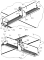
- a pusher assembly for a row of articles in a sales area which mainly comprises a separator 100, a tray or floor 200, a front stop element 250, a pusher 400 and a pusher spring not shown in the figures.
- a front rail 500 fixed by any suitable means such as screwing, gluing, clipping, along the front edge of a piece of furniture, here of a shelf T of a sales presentation equipment, and on which the front regions of several pusher assemblies are intended to be engaged and fixed, as will be detailed below.
- the separator 100 is constituted by a thin element, which is fixed to the plate 200 by appropriate cooperating arrangements, here two generally vertical barrels 201, 202 located along a lateral edge of the plate 200 in the front part and in the rear part, respectively, open towards each other, and in which the front and rear edges 101, 102 of the separator 100 are fitted.
- the separator 100 may be integral with the plate 200, or may be entirely separate from the plate and fixed to the rail 500 and/or at other attachment points.
- the front stop element 250 is here made in one piece with the plate 200. It projects upwards transversely to the longitudinal direction of movement of the pusher 400, at a height chosen so as not to obstruct the gripping by a consumer of a product (not shown) located furthest forward in a row of products received in the pusher assembly and resting against the stop element 250.
- the pusher assembly also includes a pusher member 400.
- This includes a generally vertically extending push portion 410 intended to be in pushing contact with the rear of the row of articles, and a sole 420.
- the pusher member 400 rests on the plate 200 under the cumulative effect of its own weight and the support of the article located furthest back in the row against the top of the sole 420.
- the pusher member 400 has a width close to that of the plate 200 and is capable of sliding on top of the plate to hold between it and the front stop 250 a row of articles (not shown).
- the pusher member 400 is biased by a spring made for example of spring steel (not shown for the sake of simplification), which comprises a spirally wound region, bearing on the rear of a thrust part 410 of the pusher member, and a hook intended to hook into an appropriate opening provided in the front region of the plate 200, in a manner known per se.
- a spring made for example of spring steel (not shown for the sake of simplification), which comprises a spirally wound region, bearing on the rear of a thrust part 410 of the pusher member, and a hook intended to hook into an appropriate opening provided in the front region of the plate 200, in a manner known per se.
- the elements 100 to 500 described above are preferably made by injection of suitable plastic materials.
- the separator 100 and the plate 200 are preferably made of polycarbonate.
- the front stop can be made for example of polycarbonate or polyethylene terephthalate.
- the pusher is preferably made of polypropylene. Naturally, other materials are possible.
- the pusher assembly comprises a locking device which firstly comprises a fixed element constituted by a front region 210 of the plate 200, just in front and at the base of the front stop element 250.
- This fixed element 210 which comprises a first part or wall 211 which extends the plate forward beyond the stop element 250, a frame 212 extending downward at the level of the front edge of the part 211, and a rear wall 213 extending parallel to the frame 212 and opposite it, substantially at the level of the stop-forming element 250 in the direction of the depth of the pusher assembly, these parts 211, 212 and 213 together delimiting a channel C of generally rectangular shape, open downwards.
- the wall 213 is here formed by a low wall constituting the front end of the plate 200 itself.
- the part 211 comprises at one of its edges, here its right edge 211a in front view, a notch 214 directed horizontally towards the opposite edge, and comprising an entry part 214a gradually narrowing in width, and a notch bottom part 214b of generally circular shape.
- the transition 214c between the parts 214a and 214b constitutes a constriction. See in particular Figures 4 And 5 . The function of this notch 214 will be explained below.
- the locking device further comprises a movable element or locking member 300.
- This member comprises a main part 310 in the form of a generally horizontal rectangular plate elongated in a transverse direction of the assembly (in the locking position, as will be described later).
- a locking part 320 which comprises a cylindrical neck 321 and, below this neck, a locking head 322 having a generally oblong shape, with a maximum length L1 (see Figures 7 and 9 ) and a maximum width L2 (see Figures 7 And 10 ).
- the width L2 is equal to or slightly greater than the diameter of the neck 321.
- the head 322 comprises, on either side of the neck 321, two generally flat surfaces intended to constitute pinching zones as will be described in detail below.
- the major axis of the head 322 extends generally perpendicular to the major axis of the plate 310.
- a notch 340 is formed whose width and depth are substantially equal to those of the finger 215.
- the locking member 300 is mounted on the fixed part 210 of the locking device by inserting the neck 321 laterally into the notch 214, until the neck passes, with temporary elastic deformation, the constriction 214c and comes to wedge itself in the bottom part 214b of the notch, the diameter of which is close to that of the neck 321. It is understood that, in this position, the locking member 300 is capable of pivoting relative to the fixed part 210 around a vertical axis A defined jointly by the bottom 214b of the notch and by the neck 321 which is engaged therein substantially without play.
- the front rail 500 here comprises a rail part itself 510, extended towards the rear by a plate 520 allowing it to be fixed to a store shelf T, for example by means of double-sided adhesive.
- the rail 510 comprises two uprights, respectively front and rear, 511, 512, extending upwards parallel to each other, the uprights ending at their upper end with a re-entrant edge, respectively 513, 514, the rail in cross section thus having the general shape of a “C” whose opening is turned upwards.
- the inner distance L3 between the members 511, 512 is slightly greater than the maximum length L1 of the locking head, while the inner distance L4 between the facing edges of the flanges 513, 514 is slightly greater than the maximum width L2 of the head 322 but less than the maximum length L1.
- the mobile element 300 Before its assembly on a T shelf equipped with the rail 500, the mobile element 300 is, if necessary, assembled on the fixed element 210 of the wedging and fixing device, in the case where this assembly is not carried out at the manufacturing stage.
- the movable element is placed, by rotation around the axis A, in the position illustrated in the Fig. 6 , where the major axis of the plate 310 is generally perpendicular to the longitudinal direction of the rail 510 and where consequently the major axis of the head 322 is generally aligned with the longitudinal direction of the rail 510.
- the pusher assembly can be wedged on the rail by engaging the head 322 inside the rail, the walls 212, 213 of the fixed part 210 coming along the external face members of the uprights 511, 512 of the rail 510, to thus block the pusher assembly in the front/rear direction.
- the bottom of the channel defined C by the elements 211, 212 and 213 comes to bear against the top of the rail 510 defined by the edges 513, 514, to wedge the front region of the pusher assembly in the vertical direction.
- the pusher assembly can freely slide laterally along the rail 510, in particular with a view to adjusting the distance between two pusher assemblies, and therefore their separators 100, depending on the width of the products to be received.
- the locking member 300 is caused to pivot around its axis A, preferably by action at the lever 330 using the operator's fingers.
- the distance between said facing surfaces at rest is chosen to be slightly less than the thickness of the edges 513, 514, this difference in thickness being determined in particular as a function of the nature of the materials constituting the movable member 100 and the rail 500, and in particular their elasticity and compressibility. Typically, this distance at rest is between 95 and 99% of the thickness of the edges.
- chamfers formed at the base of the faces opposite the edges 513, 514 of the rail, and/or on the upper part of the head, and obtained during injection can facilitate the engagement of the working areas of the head 322 under the edges 513, 514 of the rail 510.
- the pusher assembly is blocked both in the lateral direction, by the friction occurring between the elements 210, 300 and 510, and in the vertical direction upwards, the head 322 wider than the free space between the two edges 513, 514 preventing any extraction of the assembly upwards.
- any additional arrangement may also be provided to stabilize the member 200 in its locked position.
- this arrangement comprises a boss 350 formed on the lower face of the plate 310 of the member 300, which engages, at the end of the locking travel, in a complementary recess 211b formed at the corresponding location on the upper surface of the wall 211.
- any auxiliary arrangement such as a coating with a higher coefficient of friction than that of the material constituting the fixed element 210, the movable member 300 and/or the rail 500, or even work on the surface condition of the parts in contact, in particular by giving them a certain roughness.
- the member 300 in its locking position, is entirely contained within the grip of the wall 211 of the fixed part, to further limit the risk of accidental unlocking and contribute to an appearance with the minimum of roughness of the row of pusher assemblies receiving their product alignments.
- the invention applies to multiple forms of pusher and separator combinations.
Landscapes
- Supports Or Holders For Household Use (AREA)
- Display Racks (AREA)
Priority Applications (2)
| Application Number | Priority Date | Filing Date | Title |
|---|---|---|---|
| EP23166278.4A EP4442167B1 (de) | 2023-04-03 | 2023-04-03 | Schiebeanordnung zur präsentation von artikeln in einer verkaufsfläche |
| ES23166278T ES3041630T3 (en) | 2023-04-03 | 2023-04-03 | Pusher assembly for displaying items in a retail surface |
Applications Claiming Priority (1)
| Application Number | Priority Date | Filing Date | Title |
|---|---|---|---|
| EP23166278.4A EP4442167B1 (de) | 2023-04-03 | 2023-04-03 | Schiebeanordnung zur präsentation von artikeln in einer verkaufsfläche |
Publications (3)
| Publication Number | Publication Date |
|---|---|
| EP4442167A1 true EP4442167A1 (de) | 2024-10-09 |
| EP4442167C0 EP4442167C0 (de) | 2025-07-30 |
| EP4442167B1 EP4442167B1 (de) | 2025-07-30 |
Family
ID=85800557
Family Applications (1)
| Application Number | Title | Priority Date | Filing Date |
|---|---|---|---|
| EP23166278.4A Active EP4442167B1 (de) | 2023-04-03 | 2023-04-03 | Schiebeanordnung zur präsentation von artikeln in einer verkaufsfläche |
Country Status (2)
| Country | Link |
|---|---|
| EP (1) | EP4442167B1 (de) |
| ES (1) | ES3041630T3 (de) |
Citations (5)
| Publication number | Priority date | Publication date | Assignee | Title |
|---|---|---|---|---|
| FR2942590A1 (fr) | 2009-02-27 | 2010-09-03 | Hl Display France | Dispositif de presentation et de distribution d'articles pour magasins. |
| WO2011075261A1 (en) | 2009-12-16 | 2011-06-23 | Rtc Industries, Inc. | Product management display system with trackless pusher mechanism |
| EP2750555A1 (de) | 2011-09-02 | 2014-07-09 | Rtc Industries, Inc. | Produktverwaltungsanzeigesystem |
| WO2014198839A1 (de) | 2013-06-12 | 2014-12-18 | Pos Tuning Udo Vosshenrich Gmbh & Co. Kg | Vorrichtung zum vorschub von waren |
| EP2952123A1 (de) * | 2014-06-04 | 2015-12-09 | POS TUNING Udo Voßhenrich GmbH & Co. KG | Warenvorschubsystem für die präsentation von waren |
-
2023
- 2023-04-03 ES ES23166278T patent/ES3041630T3/es active Active
- 2023-04-03 EP EP23166278.4A patent/EP4442167B1/de active Active
Patent Citations (5)
| Publication number | Priority date | Publication date | Assignee | Title |
|---|---|---|---|---|
| FR2942590A1 (fr) | 2009-02-27 | 2010-09-03 | Hl Display France | Dispositif de presentation et de distribution d'articles pour magasins. |
| WO2011075261A1 (en) | 2009-12-16 | 2011-06-23 | Rtc Industries, Inc. | Product management display system with trackless pusher mechanism |
| EP2750555A1 (de) | 2011-09-02 | 2014-07-09 | Rtc Industries, Inc. | Produktverwaltungsanzeigesystem |
| WO2014198839A1 (de) | 2013-06-12 | 2014-12-18 | Pos Tuning Udo Vosshenrich Gmbh & Co. Kg | Vorrichtung zum vorschub von waren |
| EP2952123A1 (de) * | 2014-06-04 | 2015-12-09 | POS TUNING Udo Voßhenrich GmbH & Co. KG | Warenvorschubsystem für die präsentation von waren |
Also Published As
| Publication number | Publication date |
|---|---|
| EP4442167C0 (de) | 2025-07-30 |
| ES3041630T3 (en) | 2025-11-13 |
| EP4442167B1 (de) | 2025-07-30 |
Similar Documents
| Publication | Publication Date | Title |
|---|---|---|
| EP1835828A1 (de) | Vorrichtung zur verteilung mindestens eines anzeigezubehörteils auf einer oberfläche mit guter anzeige | |
| CA2218410A1 (fr) | Dispositif de montage de la tablette arriere d'un vehicule automobile | |
| EP0986980A1 (de) | Schubvorrichtung zur Präsentation von Artikeln auf einem Regal | |
| EP0069003A1 (de) | Einrichtung zum Lagerung und Verteilung von Gegenständen, z.B. Schachteln | |
| FR2794701A1 (fr) | Dispositif pour retenir et articuler une tablette arriere amovible de vehicule automobile | |
| EP0900037A1 (de) | Zusammensetzbarer stuhl | |
| EP3995045B1 (de) | Tisch mit mittelauszug | |
| EP1925236A1 (de) | Ordnungsvorrichtung, die zwischen Hoch- und Tiefposition umstellbar ist | |
| EP4442167B1 (de) | Schiebeanordnung zur präsentation von artikeln in einer verkaufsfläche | |
| FR2760706A1 (fr) | Dispositif de rangement pour habitacle interieur de vehicule, notamment vehicule automobile | |
| FR2862504A1 (fr) | Meuble de stockage et de presentation de produits | |
| EP0453474A1 (de) | Mit einem profil verbundene abstützvorrichtung, insbesondere zum abstützen einer platte oder eines zwischenstücks eines bausatzähnlichen oder zerlegbaren elementes | |
| EP1678698B1 (de) | Anzeigevorrichtung insbesondere zur elektronische anzeige von preisen | |
| FR2651145A1 (fr) | Fixation de securite pour ski. | |
| EP1013197B1 (de) | Regale | |
| FR3061484B1 (fr) | Coffret pour bouteille comportant des moyens de retenue de la bouteille | |
| FR3020783A1 (fr) | Dispositif pour le classement de dossiers en position verticale sur des etageres | |
| FR2807924A1 (fr) | Systeme de reglage vertical d'un support sur un montant et son utilisation pour la realisation d'etageres | |
| FR2743873A1 (fr) | Appareil frigorifique dote d'etageres et de cassettes perfectionnees | |
| FR2809473A1 (fr) | Support pour la fixation d'une tablette a une paroi | |
| FR2876892A1 (fr) | Butee reglable coulissant sur un separateur d'articles | |
| FR2875113A1 (fr) | Tablette de rayonnage a faible charge pour presentoir en grande distribution | |
| CH720341A2 (fr) | Mécanisme de fixation pour bracelet interchangeable à un boîtier et boîtier de montre | |
| FR2546604A1 (fr) | Support formant console ou butee mobile, monte en appui et coulissant le long d'un profile | |
| EP1564420A1 (de) | Vorrichtung zum Herstellen der Rechtwinkligkeit für Möbeln |
Legal Events
| Date | Code | Title | Description |
|---|---|---|---|
| PUAI | Public reference made under article 153(3) epc to a published international application that has entered the european phase |
Free format text: ORIGINAL CODE: 0009012 |
|
| STAA | Information on the status of an ep patent application or granted ep patent |
Free format text: STATUS: THE APPLICATION HAS BEEN PUBLISHED |
|
| AK | Designated contracting states |
Kind code of ref document: A1 Designated state(s): AL AT BE BG CH CY CZ DE DK EE ES FI FR GB GR HR HU IE IS IT LI LT LU LV MC ME MK MT NL NO PL PT RO RS SE SI SK SM TR |
|
| STAA | Information on the status of an ep patent application or granted ep patent |
Free format text: STATUS: REQUEST FOR EXAMINATION WAS MADE |
|
| 17P | Request for examination filed |
Effective date: 20250106 |
|
| GRAP | Despatch of communication of intention to grant a patent |
Free format text: ORIGINAL CODE: EPIDOSNIGR1 |
|
| STAA | Information on the status of an ep patent application or granted ep patent |
Free format text: STATUS: GRANT OF PATENT IS INTENDED |
|
| INTG | Intention to grant announced |
Effective date: 20250313 |
|
| GRAS | Grant fee paid |
Free format text: ORIGINAL CODE: EPIDOSNIGR3 |
|
| GRAA | (expected) grant |
Free format text: ORIGINAL CODE: 0009210 |
|
| STAA | Information on the status of an ep patent application or granted ep patent |
Free format text: STATUS: THE PATENT HAS BEEN GRANTED |
|
| AK | Designated contracting states |
Kind code of ref document: B1 Designated state(s): AL AT BE BG CH CY CZ DE DK EE ES FI FR GB GR HR HU IE IS IT LI LT LU LV MC ME MK MT NL NO PL PT RO RS SE SI SK SM TR |
|
| REG | Reference to a national code |
Ref country code: GB Ref legal event code: FG4D Free format text: NOT ENGLISH |
|
| REG | Reference to a national code |
Ref country code: CH Ref legal event code: EP |
|
| REG | Reference to a national code |
Ref country code: DE Ref legal event code: R096 Ref document number: 602023005121 Country of ref document: DE |
|
| REG | Reference to a national code |
Ref country code: IE Ref legal event code: FG4D Free format text: LANGUAGE OF EP DOCUMENT: FRENCH |
|
| U01 | Request for unitary effect filed |
Effective date: 20250827 |
|
| U07 | Unitary effect registered |
Designated state(s): AT BE BG DE DK EE FI FR IT LT LU LV MT NL PT RO SE SI Effective date: 20250902 |
|
| REG | Reference to a national code |
Ref country code: ES Ref legal event code: FG2A Ref document number: 3041630 Country of ref document: ES Kind code of ref document: T3 Effective date: 20251113 |
|
| PG25 | Lapsed in a contracting state [announced via postgrant information from national office to epo] |
Ref country code: IS Free format text: LAPSE BECAUSE OF FAILURE TO SUBMIT A TRANSLATION OF THE DESCRIPTION OR TO PAY THE FEE WITHIN THE PRESCRIBED TIME-LIMIT Effective date: 20251130 |
|
| PG25 | Lapsed in a contracting state [announced via postgrant information from national office to epo] |
Ref country code: NO Free format text: LAPSE BECAUSE OF FAILURE TO SUBMIT A TRANSLATION OF THE DESCRIPTION OR TO PAY THE FEE WITHIN THE PRESCRIBED TIME-LIMIT Effective date: 20251030 |
|
| PG25 | Lapsed in a contracting state [announced via postgrant information from national office to epo] |
Ref country code: HR Free format text: LAPSE BECAUSE OF FAILURE TO SUBMIT A TRANSLATION OF THE DESCRIPTION OR TO PAY THE FEE WITHIN THE PRESCRIBED TIME-LIMIT Effective date: 20250730 |
|
| PG25 | Lapsed in a contracting state [announced via postgrant information from national office to epo] |
Ref country code: GR Free format text: LAPSE BECAUSE OF FAILURE TO SUBMIT A TRANSLATION OF THE DESCRIPTION OR TO PAY THE FEE WITHIN THE PRESCRIBED TIME-LIMIT Effective date: 20251031 |
|
| PG25 | Lapsed in a contracting state [announced via postgrant information from national office to epo] |
Ref country code: PL Free format text: LAPSE BECAUSE OF FAILURE TO SUBMIT A TRANSLATION OF THE DESCRIPTION OR TO PAY THE FEE WITHIN THE PRESCRIBED TIME-LIMIT Effective date: 20250730 |
|
| PG25 | Lapsed in a contracting state [announced via postgrant information from national office to epo] |
Ref country code: RS Free format text: LAPSE BECAUSE OF FAILURE TO SUBMIT A TRANSLATION OF THE DESCRIPTION OR TO PAY THE FEE WITHIN THE PRESCRIBED TIME-LIMIT Effective date: 20251030 |
|
| PG25 | Lapsed in a contracting state [announced via postgrant information from national office to epo] |
Ref country code: SM Free format text: LAPSE BECAUSE OF FAILURE TO SUBMIT A TRANSLATION OF THE DESCRIPTION OR TO PAY THE FEE WITHIN THE PRESCRIBED TIME-LIMIT Effective date: 20250730 |
|
| PG25 | Lapsed in a contracting state [announced via postgrant information from national office to epo] |
Ref country code: CZ Free format text: LAPSE BECAUSE OF FAILURE TO SUBMIT A TRANSLATION OF THE DESCRIPTION OR TO PAY THE FEE WITHIN THE PRESCRIBED TIME-LIMIT Effective date: 20250730 |
|
| PG25 | Lapsed in a contracting state [announced via postgrant information from national office to epo] |
Ref country code: SK Free format text: LAPSE BECAUSE OF FAILURE TO SUBMIT A TRANSLATION OF THE DESCRIPTION OR TO PAY THE FEE WITHIN THE PRESCRIBED TIME-LIMIT Effective date: 20250730 |
|
| U1N | Appointed representative for the unitary patent procedure changed after the registration of the unitary effect |
Representative=s name: MARKS & CLERK LLP; GB |
|
| U20 | Renewal fee for the european patent with unitary effect paid |
Year of fee payment: 4 Effective date: 20260326 |