EP4442508A2 - Aktive beleuchtungsvorrichtung an einem fahrrad - Google Patents
Aktive beleuchtungsvorrichtung an einem fahrrad Download PDFInfo
- Publication number
- EP4442508A2 EP4442508A2 EP24190443.2A EP24190443A EP4442508A2 EP 4442508 A2 EP4442508 A2 EP 4442508A2 EP 24190443 A EP24190443 A EP 24190443A EP 4442508 A2 EP4442508 A2 EP 4442508A2
- Authority
- EP
- European Patent Office
- Prior art keywords
- light
- light source
- optic
- bicycle
- control unit
- Prior art date
- Legal status (The legal status is an assumption and is not a legal conclusion. Google has not performed a legal analysis and makes no representation as to the accuracy of the status listed.)
- Pending
Links
Images

Classifications
-
- B—PERFORMING OPERATIONS; TRANSPORTING
- B60—VEHICLES IN GENERAL
- B60Q—ARRANGEMENT OF SIGNALLING OR LIGHTING DEVICES, THE MOUNTING OR SUPPORTING THEREOF OR CIRCUITS THEREFOR, FOR VEHICLES IN GENERAL
- B60Q1/00—Arrangement of optical signalling or lighting devices, the mounting or supporting thereof or circuits therefor
- B60Q1/02—Arrangement of optical signalling or lighting devices, the mounting or supporting thereof or circuits therefor the devices being primarily intended to illuminate the way ahead or to illuminate other areas of way or environments
- B60Q1/04—Arrangement of optical signalling or lighting devices, the mounting or supporting thereof or circuits therefor the devices being primarily intended to illuminate the way ahead or to illuminate other areas of way or environments the devices being headlights
- B60Q1/06—Arrangement of optical signalling or lighting devices, the mounting or supporting thereof or circuits therefor the devices being primarily intended to illuminate the way ahead or to illuminate other areas of way or environments the devices being headlights adjustable, e.g. remotely-controlled from inside vehicle
- B60Q1/08—Arrangement of optical signalling or lighting devices, the mounting or supporting thereof or circuits therefor the devices being primarily intended to illuminate the way ahead or to illuminate other areas of way or environments the devices being headlights adjustable, e.g. remotely-controlled from inside vehicle automatically
- B60Q1/12—Arrangement of optical signalling or lighting devices, the mounting or supporting thereof or circuits therefor the devices being primarily intended to illuminate the way ahead or to illuminate other areas of way or environments the devices being headlights adjustable, e.g. remotely-controlled from inside vehicle automatically due to steering position
-
- B—PERFORMING OPERATIONS; TRANSPORTING
- B60—VEHICLES IN GENERAL
- B60Q—ARRANGEMENT OF SIGNALLING OR LIGHTING DEVICES, THE MOUNTING OR SUPPORTING THEREOF OR CIRCUITS THEREFOR, FOR VEHICLES IN GENERAL
- B60Q1/00—Arrangement of optical signalling or lighting devices, the mounting or supporting thereof or circuits therefor
- B60Q1/02—Arrangement of optical signalling or lighting devices, the mounting or supporting thereof or circuits therefor the devices being primarily intended to illuminate the way ahead or to illuminate other areas of way or environments
- B60Q1/04—Arrangement of optical signalling or lighting devices, the mounting or supporting thereof or circuits therefor the devices being primarily intended to illuminate the way ahead or to illuminate other areas of way or environments the devices being headlights
- B60Q1/06—Arrangement of optical signalling or lighting devices, the mounting or supporting thereof or circuits therefor the devices being primarily intended to illuminate the way ahead or to illuminate other areas of way or environments the devices being headlights adjustable, e.g. remotely-controlled from inside vehicle
- B60Q1/08—Arrangement of optical signalling or lighting devices, the mounting or supporting thereof or circuits therefor the devices being primarily intended to illuminate the way ahead or to illuminate other areas of way or environments the devices being headlights adjustable, e.g. remotely-controlled from inside vehicle automatically
- B60Q1/10—Arrangement of optical signalling or lighting devices, the mounting or supporting thereof or circuits therefor the devices being primarily intended to illuminate the way ahead or to illuminate other areas of way or environments the devices being headlights adjustable, e.g. remotely-controlled from inside vehicle automatically due to vehicle inclination, e.g. due to load distribution
-
- B—PERFORMING OPERATIONS; TRANSPORTING
- B60—VEHICLES IN GENERAL
- B60Q—ARRANGEMENT OF SIGNALLING OR LIGHTING DEVICES, THE MOUNTING OR SUPPORTING THEREOF OR CIRCUITS THEREFOR, FOR VEHICLES IN GENERAL
- B60Q1/00—Arrangement of optical signalling or lighting devices, the mounting or supporting thereof or circuits therefor
- B60Q1/02—Arrangement of optical signalling or lighting devices, the mounting or supporting thereof or circuits therefor the devices being primarily intended to illuminate the way ahead or to illuminate other areas of way or environments
- B60Q1/04—Arrangement of optical signalling or lighting devices, the mounting or supporting thereof or circuits therefor the devices being primarily intended to illuminate the way ahead or to illuminate other areas of way or environments the devices being headlights
- B60Q1/14—Arrangement of optical signalling or lighting devices, the mounting or supporting thereof or circuits therefor the devices being primarily intended to illuminate the way ahead or to illuminate other areas of way or environments the devices being headlights having dimming means
- B60Q1/1415—Dimming circuits
- B60Q1/1423—Automatic dimming circuits, i.e. switching between high beam and low beam due to change of ambient light or light level in road traffic
-
- B—PERFORMING OPERATIONS; TRANSPORTING
- B62—LAND VEHICLES FOR TRAVELLING OTHERWISE THAN ON RAILS
- B62J—CYCLE SADDLES OR SEATS; AUXILIARY DEVICES OR ACCESSORIES SPECIALLY ADAPTED TO CYCLES AND NOT OTHERWISE PROVIDED FOR, e.g. ARTICLE CARRIERS OR CYCLE PROTECTORS
- B62J45/00—Electrical equipment arrangements specially adapted for use as accessories on cycles, not otherwise provided for
- B62J45/40—Sensor arrangements; Mounting thereof
- B62J45/41—Sensor arrangements; Mounting thereof characterised by the type of sensor
- B62J45/412—Speed sensors
-
- B—PERFORMING OPERATIONS; TRANSPORTING
- B62—LAND VEHICLES FOR TRAVELLING OTHERWISE THAN ON RAILS
- B62J—CYCLE SADDLES OR SEATS; AUXILIARY DEVICES OR ACCESSORIES SPECIALLY ADAPTED TO CYCLES AND NOT OTHERWISE PROVIDED FOR, e.g. ARTICLE CARRIERS OR CYCLE PROTECTORS
- B62J45/00—Electrical equipment arrangements specially adapted for use as accessories on cycles, not otherwise provided for
- B62J45/40—Sensor arrangements; Mounting thereof
- B62J45/41—Sensor arrangements; Mounting thereof characterised by the type of sensor
- B62J45/415—Inclination sensors
- B62J45/4151—Inclination sensors for sensing lateral inclination of the cycle
-
- B—PERFORMING OPERATIONS; TRANSPORTING
- B62—LAND VEHICLES FOR TRAVELLING OTHERWISE THAN ON RAILS
- B62J—CYCLE SADDLES OR SEATS; AUXILIARY DEVICES OR ACCESSORIES SPECIALLY ADAPTED TO CYCLES AND NOT OTHERWISE PROVIDED FOR, e.g. ARTICLE CARRIERS OR CYCLE PROTECTORS
- B62J6/00—Arrangement of optical signalling or lighting devices on cycles; Mounting or supporting thereof; Circuits therefor
- B62J6/01—Electric circuits
-
- B—PERFORMING OPERATIONS; TRANSPORTING
- B62—LAND VEHICLES FOR TRAVELLING OTHERWISE THAN ON RAILS
- B62J—CYCLE SADDLES OR SEATS; AUXILIARY DEVICES OR ACCESSORIES SPECIALLY ADAPTED TO CYCLES AND NOT OTHERWISE PROVIDED FOR, e.g. ARTICLE CARRIERS OR CYCLE PROTECTORS
- B62J6/00—Arrangement of optical signalling or lighting devices on cycles; Mounting or supporting thereof; Circuits therefor
- B62J6/01—Electric circuits
- B62J6/015—Electric circuits using electrical power not supplied by the cycle motor generator, e.g. using batteries or piezo elements
-
- B—PERFORMING OPERATIONS; TRANSPORTING
- B62—LAND VEHICLES FOR TRAVELLING OTHERWISE THAN ON RAILS
- B62J—CYCLE SADDLES OR SEATS; AUXILIARY DEVICES OR ACCESSORIES SPECIALLY ADAPTED TO CYCLES AND NOT OTHERWISE PROVIDED FOR, e.g. ARTICLE CARRIERS OR CYCLE PROTECTORS
- B62J6/00—Arrangement of optical signalling or lighting devices on cycles; Mounting or supporting thereof; Circuits therefor
- B62J6/02—Headlights
- B62J6/022—Headlights specially adapted for motorcycles or the like
- B62J6/023—Headlights specially adapted for motorcycles or the like responsive to the lean angle of the cycle, e.g. changing intensity or switching sub-lights when cornering
-
- B—PERFORMING OPERATIONS; TRANSPORTING
- B62—LAND VEHICLES FOR TRAVELLING OTHERWISE THAN ON RAILS
- B62J—CYCLE SADDLES OR SEATS; AUXILIARY DEVICES OR ACCESSORIES SPECIALLY ADAPTED TO CYCLES AND NOT OTHERWISE PROVIDED FOR, e.g. ARTICLE CARRIERS OR CYCLE PROTECTORS
- B62J6/00—Arrangement of optical signalling or lighting devices on cycles; Mounting or supporting thereof; Circuits therefor
- B62J6/02—Headlights
- B62J6/022—Headlights specially adapted for motorcycles or the like
- B62J6/024—Switching between high and low beam
-
- B—PERFORMING OPERATIONS; TRANSPORTING
- B62—LAND VEHICLES FOR TRAVELLING OTHERWISE THAN ON RAILS
- B62J—CYCLE SADDLES OR SEATS; AUXILIARY DEVICES OR ACCESSORIES SPECIALLY ADAPTED TO CYCLES AND NOT OTHERWISE PROVIDED FOR, e.g. ARTICLE CARRIERS OR CYCLE PROTECTORS
- B62J6/00—Arrangement of optical signalling or lighting devices on cycles; Mounting or supporting thereof; Circuits therefor
- B62J6/02—Headlights
- B62J6/028—Headlights specially adapted for rider-propelled cycles with or without additional source of power
-
- B—PERFORMING OPERATIONS; TRANSPORTING
- B62—LAND VEHICLES FOR TRAVELLING OTHERWISE THAN ON RAILS
- B62J—CYCLE SADDLES OR SEATS; AUXILIARY DEVICES OR ACCESSORIES SPECIALLY ADAPTED TO CYCLES AND NOT OTHERWISE PROVIDED FOR, e.g. ARTICLE CARRIERS OR CYCLE PROTECTORS
- B62J6/00—Arrangement of optical signalling or lighting devices on cycles; Mounting or supporting thereof; Circuits therefor
- B62J6/02—Headlights
- B62J6/028—Headlights specially adapted for rider-propelled cycles with or without additional source of power
- B62J6/03—Supporting means therefor, e.g. mounting brackets
-
- B—PERFORMING OPERATIONS; TRANSPORTING
- B60—VEHICLES IN GENERAL
- B60Q—ARRANGEMENT OF SIGNALLING OR LIGHTING DEVICES, THE MOUNTING OR SUPPORTING THEREOF OR CIRCUITS THEREFOR, FOR VEHICLES IN GENERAL
- B60Q2300/00—Indexing codes for automatically adjustable headlamps or automatically dimmable headlamps
- B60Q2300/10—Indexing codes relating to particular vehicle conditions
- B60Q2300/11—Linear movements of the vehicle
- B60Q2300/112—Vehicle speed
-
- B—PERFORMING OPERATIONS; TRANSPORTING
- B60—VEHICLES IN GENERAL
- B60Q—ARRANGEMENT OF SIGNALLING OR LIGHTING DEVICES, THE MOUNTING OR SUPPORTING THEREOF OR CIRCUITS THEREFOR, FOR VEHICLES IN GENERAL
- B60Q2300/00—Indexing codes for automatically adjustable headlamps or automatically dimmable headlamps
- B60Q2300/10—Indexing codes relating to particular vehicle conditions
- B60Q2300/13—Attitude of the vehicle body
- B60Q2300/136—Roll
-
- B—PERFORMING OPERATIONS; TRANSPORTING
- B60—VEHICLES IN GENERAL
- B60Q—ARRANGEMENT OF SIGNALLING OR LIGHTING DEVICES, THE MOUNTING OR SUPPORTING THEREOF OR CIRCUITS THEREFOR, FOR VEHICLES IN GENERAL
- B60Q2300/00—Indexing codes for automatically adjustable headlamps or automatically dimmable headlamps
- B60Q2300/30—Indexing codes relating to the vehicle environment
- B60Q2300/305—Calendar date or clock time
-
- B—PERFORMING OPERATIONS; TRANSPORTING
- B62—LAND VEHICLES FOR TRAVELLING OTHERWISE THAN ON RAILS
- B62J—CYCLE SADDLES OR SEATS; AUXILIARY DEVICES OR ACCESSORIES SPECIALLY ADAPTED TO CYCLES AND NOT OTHERWISE PROVIDED FOR, e.g. ARTICLE CARRIERS OR CYCLE PROTECTORS
- B62J6/00—Arrangement of optical signalling or lighting devices on cycles; Mounting or supporting thereof; Circuits therefor
- B62J6/16—Arrangement of switches
- B62J6/165—Wireless switches
Definitions
- the invention relates to an active lighting device portable or placed on a vehicle with at least one wheel, such as a bicycle.
- each lighting device has a first optic with at least one first light source, and a second optic with at least one second light source, which are placed partly on the vehicle.
- a lighting device having an appropriate adjustment of the intensity of the light generated by headlights or other light sources.
- Such a lighting device may also be adapted to direct the beam of light according to the turns to be made in the dark or to avoid dazzling a driver of a vehicle to be passed on the road.
- the patent application WO 2017/023293 A1 describes an intelligent illumination system for a two-wheeled vehicle, such as a bicycle. It comprises an arrangement of LED light-emitting diodes, which can be independently selected to define a desired light intensity. Motors are also provided to orient the light according to the height or inclination of the bicycle, sensors for movement or light intensity, and a light arrangement according to the speed of the bicycle. However, all the LED diodes are oriented at the same time by the motors and not independently of each other. Furthermore, nothing is specified concerning the orientation of each beam of light of the LED diodes to adapt the radiation distance and the intensity of each diode LED depending on the speed or intensity of light detected, which can be a disadvantage.
- a light arrangement may be provided on the front fork of the bicycle or also on the helmet of the person riding the bicycle. It comprises a motion detector for sensing acceleration and speed, and means for rotating the light source according to a turn or speed and also to the movement of the cyclist's head in such a way that the beam of light is always in line with the direction of the cyclist's eyes with respect to the road.
- a motion detector for sensing acceleration and speed
- there is no provision for orienting two light sources differently to illuminate the road according to speed or ambient brightness which may be a disadvantage.
- the patent EP 3 036 149 B1 describes a lighting device for a bicycle with several LED diodes available. A light sensor is also provided. A control element is provided for comparing the acceleration, orientation and speed of the cyclist according to reference data. A selection of the LED diodes is also provided, but also not for differently directing at least two light sources to illuminate the route followed, which is a disadvantage.
- the invention therefore aims to overcome the drawbacks mentioned above in order to produce an active lighting device that is portable or placed on a bicycle with at least two wheels, easy to use and without complications, to enable good lighting taking into account the speed or inclination of the vehicle.
- the invention relates to an active lighting device portable or placed on a bicycle with at least two wheels, which comprises the characteristics of independent claim 1.
- An advantage of the lighting device according to the invention lies in the fact that a light sensor of the device detects the intensity of the ambient light so as to activate the light source(s) of the optics A and B, if the ambient light intensity is below a determined light threshold.
- the activation of the light sources can be done automatically on command of a control unit powered by a supply voltage source, such as a battery.
- the light intensity of the activated light sources is managed by the control unit inversely proportional to the intensity of the ambient light.
- a speed sensor is provided in the lighting device to activate the light source of the optic A only if a speed of the bicycle in use exceeds a determined speed threshold.
- the light source of the optic B can be activated as soon as the ambient light intensity is below the determined light threshold, and independently of the speed of the bicycle.
- At least one orientation or tilt detector may also be provided in the lighting device to orient the light sources according to a turn made by the bicycle.
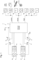
- the lighting device 1 mainly comprises two optics referenced A and B.
- the first optic A comprises at least one first light source 16, while the second optic B comprises at least one second light source 17.
- the first light source 16 is provided for long-distance illumination and preferably with variable intensity.
- the second light source 17 is provided for short-distance illumination and preferably with variable intensity.
- Each light source 16, 17 is a light-emitting diode or a group of light-emitting diodes selectable by a control unit 2 or all activatable at the same time.
- each optic A and B also comprises, in addition to the light sources 16, 17, an arrangement of lenses and mirrors (not shown) for providing a light beam, as well as a drive means 6, 7 composed of one or two electric motors, or even two pistons or two jacks.
- a first drive means 6 is shown forming part of the first optic A and a second drive means 7 forming part of the second optic B.
- each drive means 6, 7 is controlled by a control unit 2 connected to a DC power source Vdd.
- This electrical power source is preferably a DC voltage source, which comes from a rechargeable or primary battery, or which is extracted and rectified from received electromagnetic radiation.
- Each drive means 6, 7 can act on the arrangement of lenses and mirrors of the optics A or B, or directly on each light source 16, 17 to orient the light beam generated by each activated light source.
- each drive means 6, 7 can comprise two motors.
- the light sources 16, 17 can be driven in rotation by each drive means 6, 7 controlled by the control unit 2 around two axes of rotation X, Y perpendicular to each other.
- the light beam generated in each optics A, B is oriented or directed in a direction Z perpendicular to the axes X, Y.
- the lighting device 1 also comprises one or more sensors 3, 4a, 4b, 5a, 5b, 5c connected to the control unit 2 to enable the activation of each light source 16, 17 according to a measured parameter.
- the control unit 2 powered by the DC voltage source Vdd, is arranged, as soon as the vehicle is used, to control the lighting of the light source(s) 16, 17 of the first and second optics A, B automatically.
- the control unit 2 may further comprise a low-frequency oscillator, which may be a quartz clock or MEMS oscillator, and at least one volatile or non-volatile memory.
- the volatile or non-volatile memory not shown, makes it possible to store measurements made by the sensor(s) and at least one calculation algorithm for the management and calculations of the measurements made by the sensors 3, 4a, 4b, 5a, 5b, 5c.
- the control unit 2 may be a calculation unit, such as a processor or microcontroller to be able to process all the signals received from the measurement sensor(s).
- the lighting device 1 mainly comprises a light intensity sensor or light sensor 3, which may be composed of a solar cell or an array of solar cells. From a brightness threshold detected by the light intensity sensor 3, the control unit 2 controls the activation of at least the second light source 17 of the second optic B for short-distance illumination.
- the light intensity threshold may depend directly on the ambient brightness where the vehicle is located in use.
- the light intensity of the activated second light source 17 is variable and inversely proportional to the change in intensity of the ambient brightness.
- the lighting device 1 comprises at least one speed sensor 4a, 4b connected to the control unit 2.
- the speed sensor 4a, 4b determines the speed of the bicycle and, from the exceeding of a determined speed threshold, controls the activation of the first light source 16 of the first optic A.
- the first light source 16 generates light if the ambient light intensity detected by the light sensor 3 is lower than a determined light threshold.
- the second light source 17 of the second optic B is activated independently of the calculated speed of the bicycle, i.e. from the moment when the ambient light intensity detected by the light sensor 3 is lower than the determined light threshold.
- the speed sensor may be a GPS receiver or equivalent 4a or preferably a magnetic sensor 4b to capture the passage of at least one permanent magnet arranged on a spoke or the rim of a wheel of the bicycle.
- the lighting device 1 may further comprise or receive a calendar 3' of the dates and times (ephemeris) of each month in the year of a place of use of the device, from which the ambient brightness is judged to be insufficient.
- the control unit 2 may memorize this calendar 3' of the determined place of use of the device to control the activation of the light sources 16, 17 of the optics A, B, if for example the determined speed threshold is also exceeded.
- This determined speed threshold may be set at 15 km/h or 25 km/h, but may be defined at another value and memorized.
- a first dimmer 10 is provided connected to the supply voltage source Vdd, which is connected to a first switch 8, which is itself connected to the first light source 16.
- the first switch 8 is controlled by the control unit 2 to activate the first light source 16, if the ambient light intensity is insufficient.
- a second dimmer 11, which is connected to the supply voltage source Vdd, is provided and connected to a second switch 9, which is itself connected to the second light source 17 of the second optic B. This second switch 9 is controlled by the control unit 2 to activate the second light source 17, if the ambient light intensity is insufficient.
- the first and second switches 8, 9 are preferably MOS transistors, such as PMOS transistors as shown, but NMOS transistors can also be considered.
- the source of the first PMOS transistor 8 is connected to the first dimmer 10, while the source of the second PMOS transistor 9 is connected to the second dimmer 11.
- the gate of the first PMOS transistor 8 is connected to the control unit 2 to make it conductive when activating the first light source 16, or non-conductive so as not to activate the first light source 16.
- the gate of the second PMOS transistor 9 is connected to the control unit 2 to make it conductive when activating the second light source 17 or non-conductive so as not to activate the second light source 17.
- each dimmer 10, 11 may be a current source, the current of which intended to pass through each light source is variable and increases when the ambient light intensity decreases below the determined light threshold. The variation of the current of each dimmer is controlled directly by the control unit 2.
- the lighting device 1 comprises at least one orientation or inclination detector 5a, 5b, 5c connected to the control unit 2.
- the orientation or inclination detector 5a, 5b, 5c determines for example a curve made by the bicycle in use on a path or a road.
- the orientation or inclination detector 5a, 5b, 5c provides an orientation signal to the control unit 2, which controls the first and second drive means 6, 7.
- These first and second drive means 6, 7 make it possible to orient the beam(s) of light generated by the light source(s) 16, 17 of the first optic A and/or of the second optic B depending on a curve made by the bicycle in use on a path or a road.
- the orientation of the beams of the light sources 16, 17 is such that, during a right turn, the light beams are oriented to the right, and vice versa during a left turn.
- the two light sources 16, 17 activated as soon as the intensity of the ambient light is below a determined light threshold.
- the first and second drive means 6, 7 directly orient the first and second light sources 16, 17 of the optics A and B.
- the orientation detector may be composed of a potentiometer 5a and/or a magnetometer 5b and/or an inclinometer 5c and/or an accelerometer 5c and/or a gyrometer 5c as will be further explained below with reference to Figures 5a to 5c .
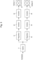
- FIG. 2 represents the first variant embodiment of the active lighting device for activating the light sources 16, 17 of the two optics A and B depending on the speed of the bicycle on a road or path according to the invention.
- the light sensor 3 is provided, which provides a signal to a first regulator 21 and a second regulator 22 of the control unit in a light intensity loop.
- the speed sensor 4 is also provided, which provides a speed signal to a speed threshold comparator 23 and a third regulator 24 of the control unit.
- the comparator 23 provides a comparison signal to a fourth regulator 25 of the control unit.
- the state of the comparison signal is either in a first state to control the activation of the first light source 16 of the optic A, or in a second state to control the non-activation of the first light source 16 of the optic A.
- a first adder 26 is provided to add the output signal of the first regulator 21 and the output signal of the fourth regulator 25, and a second adder 27 is provided to add the output signal of the second regulator 22 and the output signal of the third regulator 24.
- the output signal of the first adder 26 controls a first dimmer 28 to vary the light intensity of the first light source 16 of the first optic A if activated.
- the output signal of the second adder 27 controls a second dimmer 29 to vary the light intensity of the second light source 17 of the second optic B always activated, if the intensity of the ambient light is below a determined light threshold.
- the light intensity of the first light source 16 is therefore determined as the sum of the first regulator 21 inversely proportional to the ambient brightness, and the fourth regulator 25 proportional to the speed of movement of the bicycle.
- the first light source 16 is only activated when a speed threshold determined by the user is exceeded, for example 25 km/h with hysteresis.
- the light intensity of the second light source 17 is therefore determined as the sum of the second regulator 22 inversely proportional to the ambient brightness, and the third regulator 24 proportional to the speed of movement of the bicycle.
- the second light source 27 is always activated independently of the measured speed, if the ambient light intensity is below a determined light threshold.
- a manual switch can also be provided so as to deactivate the lighting device with all the light sources.
- Said light sources can also be deactivated after a period of non-use of the bicycle, that is to say after a determined time without movement for example after 5 minutes.
- each dimmer can be connected to each light source 16, 17 by a respective switch controlled by the control unit.
- FIG 3 represents a second variant embodiment of the active lighting device for the orientation of the light sources 16, 17 of the optics A and B when taking a bend on a road or a path according to the invention.
- At least one orientation or inclination detector 5 is provided, which provides a signal to a first regulator 31 and to a second regulator 32.
- the first regulator 31 provides an output signal to a first voltage regulator 33
- the second regulator 32 provides an output signal to a second voltage regulator 34.
- the first voltage regulator 33 controls a first actuator 35, which is at least one electric motor.
- This first actuator 35 receives control signals from the first regulator 33, such as pulse width modulated (PWM) signals for moving or orienting for example the first light source 16 of the first optic A.
- the second voltage regulator 34 controls a second actuator 36, which is at least one electric motor.
- This second actuator 36 receives control signals from the second regulator 34, such as pulse width modulated (PWM) signals for moving or orienting for example the second light source 17 of the second optic B.
- PWM pulse width modulated
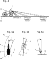
- FIG 4 schematically represents a bicycle 100 on a road 50 or a path with the activated light sources of the two optics A and B of the active lighting device 1.
- the two light sources are activated, if the speed of the bicycle is above a determined speed threshold and if the ambient light intensity is insufficient, otherwise only the second light source of the optic B is activated.
- the light intensity I LUM (v, I AMB ) of the first light source of the optic A depends on the speed v of the bicycle 100, and on the ambient light intensity I AMB .
- the light intensity I LUM (I AMB ) of the second light source of the optic B depends only on the ambient light intensity I AMB .
- the more the speed of the bicycle increases the more the light beam of the first light source of the optics A increases in luminous intensity.
- the first drive means of the optics A directs said light source to illuminate even further up to a vertical azimuth, which tends towards 0.
- the luminous intensity of each light source can vary proportionally to the inverse of the ambient light intensity, or even in stages.
- FIGS. 5a, 5b, 5c schematically show a bicycle 100 on a road 50 or a path taking a bend to orient the light sources of the optics A and B of the active lighting device 1.
- Each optic A, B can be mounted for example on a handlebar of the bicycle 100.
- the orientation or inclination detector(s) are for example a magnetometer 5b or an inclinometer 5c or an accelerometer 5c or a gyrometer 5c or a potentiometer 5a or a combination of these detectors as previously mentioned.
- the orientation or tilt sensor may be mounted on a support, such as a helmet of the user E of the bicycle 100 and to provide an orientation signal by wireless two-way communication to the control unit arranged on the handlebar of the bicycle 100. This makes it possible to control the orientation of the light source(s) by a movement of the head of the user E of the bicycle 100.
- the two light sources of the optics A and B of the lighting device 1 are activated, and must be oriented by the drive means on command of the control unit according to an angle ⁇ depending on the bend made on the road 50.
- control unit takes into account a rotation angle ⁇ of the front wheel D of the bicycle and also the angular movement ⁇ of the head of the user E of the bicycle relative to the direction of the rear wheel F.
- the inclination of the bicycle with the user E at an angle ⁇ relative to the road 50 can also be taken into account to orient the light sources.
Landscapes
- Engineering & Computer Science (AREA)
- Mechanical Engineering (AREA)
- Lighting Device Outwards From Vehicle And Optical Signal (AREA)
- Circuit Arrangement For Electric Light Sources In General (AREA)
Applications Claiming Priority (2)
| Application Number | Priority Date | Filing Date | Title |
|---|---|---|---|
| EP18191097.7A EP3616989A1 (de) | 2018-08-28 | 2018-08-28 | Tragbare oder an einem fahrzeug befestigte aktive beleuchtungsvorrichtung |
| EP19184419.0A EP3616991B1 (de) | 2018-08-28 | 2019-07-04 | An einem fahrrad befestigte aktive beleuchtungsvorrichtung |
Related Parent Applications (2)
| Application Number | Title | Priority Date | Filing Date |
|---|---|---|---|
| EP19184419.0A Division EP3616991B1 (de) | 2018-08-28 | 2019-07-04 | An einem fahrrad befestigte aktive beleuchtungsvorrichtung |
| EP19184419.0A Division-Into EP3616991B1 (de) | 2018-08-28 | 2019-07-04 | An einem fahrrad befestigte aktive beleuchtungsvorrichtung |
Publications (2)
| Publication Number | Publication Date |
|---|---|
| EP4442508A2 true EP4442508A2 (de) | 2024-10-09 |
| EP4442508A3 EP4442508A3 (de) | 2024-12-18 |
Family
ID=63490216
Family Applications (3)
| Application Number | Title | Priority Date | Filing Date |
|---|---|---|---|
| EP18191097.7A Withdrawn EP3616989A1 (de) | 2018-08-28 | 2018-08-28 | Tragbare oder an einem fahrzeug befestigte aktive beleuchtungsvorrichtung |
| EP19184419.0A Active EP3616991B1 (de) | 2018-08-28 | 2019-07-04 | An einem fahrrad befestigte aktive beleuchtungsvorrichtung |
| EP24190443.2A Pending EP4442508A3 (de) | 2018-08-28 | 2019-07-04 | Aktive beleuchtungsvorrichtung an einem fahrrad |
Family Applications Before (2)
| Application Number | Title | Priority Date | Filing Date |
|---|---|---|---|
| EP18191097.7A Withdrawn EP3616989A1 (de) | 2018-08-28 | 2018-08-28 | Tragbare oder an einem fahrzeug befestigte aktive beleuchtungsvorrichtung |
| EP19184419.0A Active EP3616991B1 (de) | 2018-08-28 | 2019-07-04 | An einem fahrrad befestigte aktive beleuchtungsvorrichtung |
Country Status (4)
| Country | Link |
|---|---|
| US (1) | US10940906B2 (de) |
| EP (3) | EP3616989A1 (de) |
| JP (1) | JP6977001B2 (de) |
| CN (1) | CN110901797B (de) |
Families Citing this family (3)
| Publication number | Priority date | Publication date | Assignee | Title |
|---|---|---|---|---|
| JP7585000B2 (ja) * | 2020-11-16 | 2024-11-18 | カワサキモータース株式会社 | 鞍乗型車両及びそのライト制御方法 |
| DE102021131816B3 (de) * | 2021-12-02 | 2023-04-27 | Jochen Klieber | Zusatzleuchtvorrichtung für ein Zweirad und Zweirad damit |
| DE102024202649A1 (de) * | 2024-03-20 | 2025-09-25 | Robert Bosch Gesellschaft mit beschränkter Haftung | Verfahren zur Detektion einer Kurvenart |
Citations (9)
| Publication number | Priority date | Publication date | Assignee | Title |
|---|---|---|---|---|
| FR2844759B1 (fr) | 2002-09-20 | 2007-04-06 | Ecole Nationale D Ingenieurs D | Phare gyrostable pour moto |
| JP2011201382A (ja) | 2010-03-25 | 2011-10-13 | Mitsuba Corp | 自転車用前照灯 |
| CN205716835U (zh) | 2016-02-18 | 2016-11-23 | 李文杰 | 一种自行车灯 |
| WO2017023293A1 (en) | 2015-08-03 | 2017-02-09 | Ford Global Technologies, Llc | Intelligent bicycle lighting system for optimal road visibility |
| US20180020528A1 (en) | 2016-07-13 | 2018-01-18 | Yam Ho Yeung | Smart lighting system and method |
| WO2018017455A1 (en) | 2016-07-18 | 2018-01-25 | Entegris, Inc. | Spacer film with integrated lamination strip |
| EP3036149B1 (de) | 2013-08-21 | 2018-04-11 | Mcaleese, William Philip | Beleuchtungsvorrichtung für ein fahrrad |
| JP2018062260A (ja) | 2016-10-13 | 2018-04-19 | ボッシュ株式会社 | 自転車用照明ユニット及び自転車 |
| WO2018112656A1 (en) | 2016-12-22 | 2018-06-28 | 2948-4292 Quebec Inc. | Adaptive light beam unit and use of same |
Family Cites Families (21)
| Publication number | Priority date | Publication date | Assignee | Title |
|---|---|---|---|---|
| JPH02121009A (ja) * | 1988-10-31 | 1990-05-08 | Suzuki Motor Co Ltd | 運転者の姿勢に基づき被制御物の方向を制御する装置 |
| JP3014253B2 (ja) * | 1993-09-17 | 2000-02-28 | 株式会社ミツバ | 自転車用前照灯装置 |
| JPH07329851A (ja) * | 1994-06-03 | 1995-12-19 | Sharp Corp | 自転車用自動点灯照明装置 |
| DE4431332A1 (de) * | 1994-09-02 | 1996-05-02 | Josic Ante | Automatisches Lichtsystem für Kraftfahrzeuge aller Art sowie ein Verfahren zur Steuerung eines Lichtsystems |
| US6587573B1 (en) | 2000-03-20 | 2003-07-01 | Gentex Corporation | System for controlling exterior vehicle lights |
| JP2001213227A (ja) * | 2000-02-04 | 2001-08-07 | Koito Mfg Co Ltd | 車輌用照明システム |
| JP2001219881A (ja) * | 2000-02-09 | 2001-08-14 | Yamaha Motor Co Ltd | 鞍乗型車両用制御装置 |
| ATE394298T1 (de) * | 2002-10-18 | 2008-05-15 | Shimano Kk | Fahrradlichtanlage |
| JP2005225426A (ja) * | 2004-02-16 | 2005-08-25 | Shimano Inc | 自転車用照明装置及びそれに装着可能な自転車用表示装置。 |
| JP2007145233A (ja) * | 2005-11-29 | 2007-06-14 | Denso Corp | 光照射システム |
| JP4656429B2 (ja) * | 2006-06-02 | 2011-03-23 | 株式会社デンソー | 前照灯制御システム |
| US20100123402A1 (en) * | 2008-11-19 | 2010-05-20 | Yi-Lun Chen | Bicycle control device |
| CN202593696U (zh) * | 2012-05-23 | 2012-12-12 | 成贯企业有限公司 | 具手自动调整照明距离功能的自行车灯 |
| US8983135B2 (en) | 2012-06-01 | 2015-03-17 | Gentex Corporation | System and method for controlling vehicle equipment responsive to a multi-stage village detection |
| JP2014000876A (ja) * | 2012-06-18 | 2014-01-09 | Yamaha Motor Co Ltd | リーン姿勢で旋回する車両用のサブヘッドライトユニット及びサブヘッドライトシステム、並びにリーン姿勢で旋回する車両 |
| CN104703869B (zh) * | 2012-10-11 | 2017-10-24 | 三菱电机株式会社 | 车辆用前照灯装置 |
| US20160001836A1 (en) * | 2014-07-02 | 2016-01-07 | Wen-Sung Lee | Intellectual bicycle lamp |
| JP6599613B2 (ja) | 2014-12-25 | 2019-10-30 | 株式会社小糸製作所 | 配光可変車両用灯具 |
| GB201511303D0 (en) * | 2015-06-26 | 2015-08-12 | Gherezghiher Amanuel And Gerez Bikes Ltd | Gerez bike |
| US9926028B2 (en) * | 2015-12-30 | 2018-03-27 | Tina Su | Assembly of a light and a watch of a bicycle capable for adjusting angle |
| JP6894195B2 (ja) * | 2016-06-14 | 2021-06-30 | 株式会社シマノ | 自転車用表示装置 |
-
2018
- 2018-08-28 EP EP18191097.7A patent/EP3616989A1/de not_active Withdrawn
-
2019
- 2019-07-04 EP EP19184419.0A patent/EP3616991B1/de active Active
- 2019-07-04 EP EP24190443.2A patent/EP4442508A3/de active Pending
- 2019-08-13 JP JP2019148340A patent/JP6977001B2/ja active Active
- 2019-08-20 US US16/545,208 patent/US10940906B2/en active Active
- 2019-08-23 CN CN201910781602.8A patent/CN110901797B/zh active Active
Patent Citations (9)
| Publication number | Priority date | Publication date | Assignee | Title |
|---|---|---|---|---|
| FR2844759B1 (fr) | 2002-09-20 | 2007-04-06 | Ecole Nationale D Ingenieurs D | Phare gyrostable pour moto |
| JP2011201382A (ja) | 2010-03-25 | 2011-10-13 | Mitsuba Corp | 自転車用前照灯 |
| EP3036149B1 (de) | 2013-08-21 | 2018-04-11 | Mcaleese, William Philip | Beleuchtungsvorrichtung für ein fahrrad |
| WO2017023293A1 (en) | 2015-08-03 | 2017-02-09 | Ford Global Technologies, Llc | Intelligent bicycle lighting system for optimal road visibility |
| CN205716835U (zh) | 2016-02-18 | 2016-11-23 | 李文杰 | 一种自行车灯 |
| US20180020528A1 (en) | 2016-07-13 | 2018-01-18 | Yam Ho Yeung | Smart lighting system and method |
| WO2018017455A1 (en) | 2016-07-18 | 2018-01-25 | Entegris, Inc. | Spacer film with integrated lamination strip |
| JP2018062260A (ja) | 2016-10-13 | 2018-04-19 | ボッシュ株式会社 | 自転車用照明ユニット及び自転車 |
| WO2018112656A1 (en) | 2016-12-22 | 2018-06-28 | 2948-4292 Quebec Inc. | Adaptive light beam unit and use of same |
Also Published As
| Publication number | Publication date |
|---|---|
| CN110901797A (zh) | 2020-03-24 |
| EP3616991A1 (de) | 2020-03-04 |
| US10940906B2 (en) | 2021-03-09 |
| EP3616989A1 (de) | 2020-03-04 |
| EP4442508A3 (de) | 2024-12-18 |
| CN110901797B (zh) | 2022-07-05 |
| EP3616991B1 (de) | 2026-05-06 |
| JP6977001B2 (ja) | 2021-12-08 |
| JP2020033006A (ja) | 2020-03-05 |
| US20200070915A1 (en) | 2020-03-05 |
Similar Documents
| Publication | Publication Date | Title |
|---|---|---|
| EP3049283B1 (de) | Vorrichtung und verfahren zur fahrassistenz | |
| EP3616991B1 (de) | An einem fahrrad befestigte aktive beleuchtungsvorrichtung | |
| FR2988493A1 (fr) | Lunettes adaptatives pour conducteur ou passager de vehicule automobile | |
| WO2017109318A1 (fr) | Tondeuse électrique anticipative et procédé de pilotage d'une telle tondeuse | |
| EP1201498A1 (de) | Vorrichtung zur automatischen Einstellung der Neigung eines Kfz-Scheinwerfers | |
| EP3617049B1 (de) | An einem fahrrad befestigte aktive beleuchtungsvorrichtung | |
| EP1821032B1 (de) | Scheinwerfer, insbesondere mit LED, für Kraftfahrzeug | |
| EP1388460A2 (de) | Steuerungseinrichtung für automatische Einstellung der Position eines Fahrzeugscheinwerfers | |
| EP2988972A1 (de) | Verfahren zur steuerung eines regulierbaren beleuchtungssystems für ein trägerfahrzeug | |
| CH715274A2 (fr) | Dispositif d'éclairage actif portable ou placé sur un vélo. | |
| FR2988052A1 (fr) | Procede d'adaptation d'au moins un parametre photometrique d'une source lumineuse de vehicule automobile et systeme d'adaptation correspondant | |
| FR2867119A1 (fr) | Dispositif destine a ajuster automatiquement l'axe de faisceau lumineux d'un phare de vehicule | |
| FR3084050A1 (fr) | Dispositif d'eclairage adaptatif pour cycles | |
| CH715275A2 (fr) | Dispositif d'éclairage actif portable ou placé sur un vélo. | |
| EP0659610B1 (de) | Selbstanpassende Regelungsvorrichtung für einen elektrisch betätigten Rückspiegel | |
| HK40116808A (zh) | 便携式有源照明设备或安装在自行车上的该设备 | |
| HK40022498A (en) | Portable active lighting device or same installed on a bicycle | |
| EP1502813B1 (de) | Kurvenlichtsystem enthaltend eine Steuervorrichtung und autonome Kurvenerkennungsmittel | |
| HK40023043B (zh) | 便携式有源照明设备 | |
| HK40023043A (zh) | 便携式有源照明设备 | |
| WO2025068323A1 (fr) | Procédé pour le contrôle dynamique d'un système d'éclairage d'un véhicule, élément informatique, programme d'ordinateur et système d'éclairage pour la mise en œuvre du procédé | |
| FR3042449A1 (fr) | Dispositif et procede de gestion des moyens de motorisation electrique d'un vehicule a assistance electrique | |
| FR3005139A1 (fr) | Procede de commande d'un systeme d'eclairage reglable, pour un vehicule porteur | |
| WO2003093056A2 (fr) | Dispositif de signalisation pour la prevention des collisions | |
| FR3062826A1 (fr) | Dispositif de correction de site pour un phare de vehicule |
Legal Events
| Date | Code | Title | Description |
|---|---|---|---|
| PUAI | Public reference made under article 153(3) epc to a published international application that has entered the european phase |
Free format text: ORIGINAL CODE: 0009012 |
|
| STAA | Information on the status of an ep patent application or granted ep patent |
Free format text: STATUS: THE APPLICATION HAS BEEN PUBLISHED |
|
| AC | Divisional application: reference to earlier application |
Ref document number: 3616991 Country of ref document: EP Kind code of ref document: P |
|
| AK | Designated contracting states |
Kind code of ref document: A2 Designated state(s): AL AT BE BG CH CY CZ DE DK EE ES FI FR GB GR HR HU IE IS IT LI LT LU LV MC MK MT NL NO PL PT RO RS SE SI SK SM TR |
|
| REG | Reference to a national code |
Ref country code: DE Ref legal event code: R079 Free format text: PREVIOUS MAIN CLASS: B60Q0001100000 Ipc: B60Q0001040000 |
|
| PUAL | Search report despatched |
Free format text: ORIGINAL CODE: 0009013 |
|
| AK | Designated contracting states |
Kind code of ref document: A3 Designated state(s): AL AT BE BG CH CY CZ DE DK EE ES FI FR GB GR HR HU IE IS IT LI LT LU LV MC MK MT NL NO PL PT RO RS SE SI SK SM TR |
|
| RIC1 | Information provided on ipc code assigned before grant |
Ipc: B60Q 1/10 20060101ALI20241113BHEP Ipc: B62J 6/02 20200101ALI20241113BHEP Ipc: B60Q 1/14 20060101ALI20241113BHEP Ipc: B60Q 1/12 20060101ALI20241113BHEP Ipc: B60Q 1/08 20060101ALI20241113BHEP Ipc: B60Q 1/04 20060101AFI20241113BHEP |
|
| P01 | Opt-out of the competence of the unified patent court (upc) registered |
Free format text: CASE NUMBER: APP_6838/2025 Effective date: 20250210 |
|
| STAA | Information on the status of an ep patent application or granted ep patent |
Free format text: STATUS: REQUEST FOR EXAMINATION WAS MADE |
|
| 17P | Request for examination filed |
Effective date: 20250618 |
|
| STAA | Information on the status of an ep patent application or granted ep patent |
Free format text: STATUS: EXAMINATION IS IN PROGRESS |
|
| 17Q | First examination report despatched |
Effective date: 20251215 |