EP4443013A1 - Ensemble palier pour transmission - Google Patents
Ensemble palier pour transmission Download PDFInfo
- Publication number
- EP4443013A1 EP4443013A1 EP23166360.0A EP23166360A EP4443013A1 EP 4443013 A1 EP4443013 A1 EP 4443013A1 EP 23166360 A EP23166360 A EP 23166360A EP 4443013 A1 EP4443013 A1 EP 4443013A1
- Authority
- EP
- European Patent Office
- Prior art keywords
- rolling
- bearing
- hollow body
- rotating body
- bearing arrangement
- Prior art date
- Legal status (The legal status is an assumption and is not a legal conclusion. Google has not performed a legal analysis and makes no representation as to the accuracy of the status listed.)
- Withdrawn
Links
- 230000005540 biological transmission Effects 0.000 title claims abstract description 40
- 238000005096 rolling process Methods 0.000 claims abstract description 403
- 238000003780 insertion Methods 0.000 description 13
- 230000037431 insertion Effects 0.000 description 13
- 238000009434 installation Methods 0.000 description 9
- 238000004519 manufacturing process Methods 0.000 description 9
- 238000013461 design Methods 0.000 description 4
- 230000036316 preload Effects 0.000 description 4
- 238000000034 method Methods 0.000 description 3
- 230000009466 transformation Effects 0.000 description 3
- 230000000295 complement effect Effects 0.000 description 2
- 238000010276 construction Methods 0.000 description 2
- 238000010438 heat treatment Methods 0.000 description 2
- 239000000314 lubricant Substances 0.000 description 2
- 238000005461 lubrication Methods 0.000 description 2
- 239000000463 material Substances 0.000 description 2
- 230000000903 blocking effect Effects 0.000 description 1
- 238000012937 correction Methods 0.000 description 1
- 238000005516 engineering process Methods 0.000 description 1
- 238000012986 modification Methods 0.000 description 1
- 230000004048 modification Effects 0.000 description 1
- 238000007789 sealing Methods 0.000 description 1
- 210000002023 somite Anatomy 0.000 description 1
- 238000003860 storage Methods 0.000 description 1
Images









Classifications
-
- F—MECHANICAL ENGINEERING; LIGHTING; HEATING; WEAPONS; BLASTING
- F16—ENGINEERING ELEMENTS AND UNITS; GENERAL MEASURES FOR PRODUCING AND MAINTAINING EFFECTIVE FUNCTIONING OF MACHINES OR INSTALLATIONS; THERMAL INSULATION IN GENERAL
- F16C—SHAFTS; FLEXIBLE SHAFTS; ELEMENTS OR CRANKSHAFT MECHANISMS; ROTARY BODIES OTHER THAN GEARING ELEMENTS; BEARINGS
- F16C19/00—Bearings with rolling contact, for exclusively rotary movement
- F16C19/22—Bearings with rolling contact, for exclusively rotary movement with bearing rollers essentially of the same size in one or more circular rows, e.g. needle bearings
- F16C19/34—Bearings with rolling contact, for exclusively rotary movement with bearing rollers essentially of the same size in one or more circular rows, e.g. needle bearings for both radial and axial load
- F16C19/38—Bearings with rolling contact, for exclusively rotary movement with bearing rollers essentially of the same size in one or more circular rows, e.g. needle bearings for both radial and axial load with two or more rows of rollers
-
- F—MECHANICAL ENGINEERING; LIGHTING; HEATING; WEAPONS; BLASTING
- F16—ENGINEERING ELEMENTS AND UNITS; GENERAL MEASURES FOR PRODUCING AND MAINTAINING EFFECTIVE FUNCTIONING OF MACHINES OR INSTALLATIONS; THERMAL INSULATION IN GENERAL
- F16C—SHAFTS; FLEXIBLE SHAFTS; ELEMENTS OR CRANKSHAFT MECHANISMS; ROTARY BODIES OTHER THAN GEARING ELEMENTS; BEARINGS
- F16C33/00—Parts of bearings; Special methods for making bearings or parts thereof
- F16C33/30—Parts of ball or roller bearings
- F16C33/37—Loose spacing bodies
- F16C33/3713—Loose spacing bodies with other rolling elements serving as spacing bodies, e.g. the spacing bodies are in rolling contact with the load carrying rolling elements
-
- F—MECHANICAL ENGINEERING; LIGHTING; HEATING; WEAPONS; BLASTING
- F16—ENGINEERING ELEMENTS AND UNITS; GENERAL MEASURES FOR PRODUCING AND MAINTAINING EFFECTIVE FUNCTIONING OF MACHINES OR INSTALLATIONS; THERMAL INSULATION IN GENERAL
- F16C—SHAFTS; FLEXIBLE SHAFTS; ELEMENTS OR CRANKSHAFT MECHANISMS; ROTARY BODIES OTHER THAN GEARING ELEMENTS; BEARINGS
- F16C33/00—Parts of bearings; Special methods for making bearings or parts thereof
- F16C33/30—Parts of ball or roller bearings
- F16C33/58—Raceways; Race rings
- F16C33/581—Raceways; Race rings integral with other parts, e.g. with housings or machine elements such as shafts or gear wheels
-
- F—MECHANICAL ENGINEERING; LIGHTING; HEATING; WEAPONS; BLASTING
- F16—ENGINEERING ELEMENTS AND UNITS; GENERAL MEASURES FOR PRODUCING AND MAINTAINING EFFECTIVE FUNCTIONING OF MACHINES OR INSTALLATIONS; THERMAL INSULATION IN GENERAL
- F16H—GEARING
- F16H1/00—Toothed gearings for conveying rotary motion
- F16H1/28—Toothed gearings for conveying rotary motion with gears having orbital motion
- F16H1/32—Toothed gearings for conveying rotary motion with gears having orbital motion in which the central axis of the gearing lies inside the periphery of an orbital gear
-
- F—MECHANICAL ENGINEERING; LIGHTING; HEATING; WEAPONS; BLASTING
- F16—ENGINEERING ELEMENTS AND UNITS; GENERAL MEASURES FOR PRODUCING AND MAINTAINING EFFECTIVE FUNCTIONING OF MACHINES OR INSTALLATIONS; THERMAL INSULATION IN GENERAL
- F16H—GEARING
- F16H57/00—General details of gearing
- F16H57/02—Gearboxes; Mounting gearing therein
- F16H57/021—Shaft support structures, e.g. partition walls, bearing eyes, casing walls or covers with bearings
-
- F—MECHANICAL ENGINEERING; LIGHTING; HEATING; WEAPONS; BLASTING
- F16—ENGINEERING ELEMENTS AND UNITS; GENERAL MEASURES FOR PRODUCING AND MAINTAINING EFFECTIVE FUNCTIONING OF MACHINES OR INSTALLATIONS; THERMAL INSULATION IN GENERAL
- F16C—SHAFTS; FLEXIBLE SHAFTS; ELEMENTS OR CRANKSHAFT MECHANISMS; ROTARY BODIES OTHER THAN GEARING ELEMENTS; BEARINGS
- F16C2361/00—Apparatus or articles in engineering in general
- F16C2361/61—Toothed gear systems, e.g. support of pinion shafts
-
- F—MECHANICAL ENGINEERING; LIGHTING; HEATING; WEAPONS; BLASTING
- F16—ENGINEERING ELEMENTS AND UNITS; GENERAL MEASURES FOR PRODUCING AND MAINTAINING EFFECTIVE FUNCTIONING OF MACHINES OR INSTALLATIONS; THERMAL INSULATION IN GENERAL
- F16H—GEARING
- F16H1/00—Toothed gearings for conveying rotary motion
- F16H1/28—Toothed gearings for conveying rotary motion with gears having orbital motion
- F16H1/32—Toothed gearings for conveying rotary motion with gears having orbital motion in which the central axis of the gearing lies inside the periphery of an orbital gear
- F16H2001/323—Toothed gearings for conveying rotary motion with gears having orbital motion in which the central axis of the gearing lies inside the periphery of an orbital gear comprising eccentric crankshafts driving or driven by a gearing
-
- F—MECHANICAL ENGINEERING; LIGHTING; HEATING; WEAPONS; BLASTING
- F16—ENGINEERING ELEMENTS AND UNITS; GENERAL MEASURES FOR PRODUCING AND MAINTAINING EFFECTIVE FUNCTIONING OF MACHINES OR INSTALLATIONS; THERMAL INSULATION IN GENERAL
- F16H—GEARING
- F16H1/00—Toothed gearings for conveying rotary motion
- F16H1/28—Toothed gearings for conveying rotary motion with gears having orbital motion
- F16H1/32—Toothed gearings for conveying rotary motion with gears having orbital motion in which the central axis of the gearing lies inside the periphery of an orbital gear
- F16H2001/325—Toothed gearings for conveying rotary motion with gears having orbital motion in which the central axis of the gearing lies inside the periphery of an orbital gear comprising a carrier with pins guiding at least one orbital gear with circular holes
Definitions
- the invention relates to a bearing arrangement for a transmission according to the preamble of claim 1.
- Cycloidal gears and planetary gears are types of gears that have a high load capacity, a small installation space requirement and a large transmission ratio and are also not self-locking.
- the cycloidal disk can be provided with a central opening and with at least one eccentric opening.
- a central eccentric shaft can extend along the central axis.
- Each of the eccentric sections corresponding to the number of cycloidal disks is arranged rotatably in a central opening of a cycloidal disk.
- the transformation means comprise a maximum number of eccentric elements corresponding to the number of eccentric openings, which are arranged together so as to be rotatable about the central axis.
- the eccentric elements are part of the rotating body, which can be connected to a shaft, can comprise this or can be comprised by this.
- a planetary gear is, for example, a spur gear or friction gear, which, in addition to shafts fixed to the frame, also has shafts that rotate on circular paths in the frame.
- the axes of the rotating shafts can run parallel to the axes of the shafts fixed to the frame.
- Planetary gears rotating on the rotating shafts orbit a central sun gear.
- axis in contrast to the term shaft, refers to a geometric axis and not to a machine element.
- a particularly high gear ratio can be achieved by a two- or multi-stage transmission that combines a cycloidal transmission forming a first gear stage and a planetary transmission forming a second gear stage.
- the terms first and second gear stage are used merely to distinguish them and do not represent a predetermined order.
- One of the reasons for this is that neither cycloidal transmissions nor planetary transmissions are self-locking. Accordingly, their input and output elements, which are formed by shafts, for example, can be swapped around in the sense that they can be driven from either shaft without blocking.
- a cycloidal gear used as a gear stage for this purpose is advantageously provided with one or more off-centre eccentric shafts mounted rotatably on the rotating body, each with a number of eccentric sections corresponding to the number of cycloidal disks, which are rotatably mounted in eccentric openings in the cycloidal disks.
- Planetary gears of the planetary gear used as a gear stage are non-rotatably connected to the eccentric eccentric shafts and are arranged together with them to rotate about the central axis.
- the eccentric eccentric shafts also form the transformation means.
- a disadvantage of both cycloidal gears and the combination of cycloidal and planetary gears in a multi-stage gear is the high assembly effort.
- this is due to the effort required to assemble the bearing elements comprising rolling elements and separators between the hollow body bearing elements that rotate relative to one another and the rotating body that rotates relative to this about the hollow body axis.
- a pair of bearing grooves is provided to accommodate a rolling bearing ring.
- the pair of bearing grooves each comprise a bearing groove in one bearing element - the hollow body - and a bearing groove opposite this in the other bearing element - the rotating body.
- the functional parts of the respective gears that are also housed in the hollow body and on the rotating body must be installed. On the other hand, this is made more difficult by the overall tight space conditions of the compactly constructed gears.
- the load-bearing capacity of the bearing arrangement which has been optimized with regard to a reasonable assembly effort, is limited.
- the moment load capacity of the bearing arrangement between the hollow body and the rotating body is limited in particular due to the single-row bearing design as a crossed roller bearing with only one rolling bearing ring between the hollow body and the rotating body in order to ensure reasonable ease of assembly.
- the rolling bearing elements of the rolling bearing rings comprising rolling elements and separators must be laboriously installed piece by piece in the correct, if necessary alternating, alignment by means of bearing groove pairs between the hollow body and the rotating body provided for receiving the rolling bearing rings.
- Loading holes must be made. This is time-consuming and prone to errors.
- the loading holes must then be closed in a separate work step. Subsequent corrections require disassembly and removal of the bearing elements through the loading holes. This takes even more time than assembly.
- One object of the invention is to obtain a higher load capacity of a bearing arrangement for a gear unit to be constructed compactly and to obtain a higher load capacity of a gear unit to be constructed compactly overall while at the same time preserving its advantageous properties, at least while maintaining a reasonable assembly effort, but preferably with reduced assembly effort.
- the invention relates to a bearing arrangement for a compact gearbox, with two bearing elements mounted rotatably relative to one another.
- the bearing elements preferably comprise a hollow body with a hollow body axis and a bearing element arranged in the hollow body around the hollow body axis. rotatably mounted rotating body. Between the bearing elements, two rolling bearing rings are arranged in two pairs of grooves spaced apart from one another along the hollow body axis.
- Each pair of grooves consists of a groove delimited by two groove walls on one bearing element and an opposite groove, also delimited by two groove walls, on the remaining bearing element.
- One groove wall of each groove is designed as a rolling element running surface, the remaining groove wall as a rolling element support surface.
- the rolling element running surfaces border on the rolling element support surfaces.
- the rolling element running surfaces are arranged opposite one another, as are the rolling element support surfaces.
- Each rolling bearing ring preferably consists of rolling bearing elements comprising, for example, alternating rolling elements and separators. An annular gap remains between the two bearing elements.
- a radial projection is formed which is delimited in the axial direction by two immediately adjacent first truncated cone surfaces which are axially offset from one another in relation to the hollow body axis and inclined in opposite directions, with a tip projecting into the annular gap towards the opposite bearing element, in which the two first truncated cone surfaces are immediately adjacent to one another, on each of these first truncated cone surfaces forming first rolling element running surfaces, the rolling elements of one rolling bearing ring of two axially spaced rolling bearing rings made up of rolling bearing elements comprising alternating rolling elements and separators roll.
- the radial projection has on its two axial flanks the two first truncated cone surfaces, which form the two first rolling element running surfaces on which the rolling elements of the two rolling bearing rings roll on the one bearing element.
- two V-grooves are recessed axially spaced apart along the hollow body axis, of which one of the groove walls each forms one of a total of two second truncated cone surfaces opposite the first rolling element running surfaces as second rolling element running surfaces forms, on each of which the rolling elements of one of the two rolling bearing rings roll on the remaining bearing element.
- the remaining groove wall of each V-groove simply forms a truncated cone-shaped second rolling element support surface, which prevents the rolling elements of the respective rolling bearing ring from sliding off the respective second rolling element running surface transversely to their rolling movement.
- one rolling bearing ring of each of the two rolling bearing rings is arranged between the respective first and second rolling element running surfaces, one rolling bearing ring on each side.
- Each of the two support surfaces serves only as a frustoconical surface-shaped first rolling element support surface, which prevents the rolling elements of the respective rolling bearing ring from sliding off the first rolling element running surface of the projection adjacent to the respective support ring, transversely to their rolling movement.
- the support surfaces project beyond the first rolling element running surfaces normal to the hollow body axis to a degree sufficient to hold the rolling bearing elements in axial position.
- the support rings thus protrude laterally from the rolling bearing elements of the rolling bearing rings partially into the annular gap between the hollow body and the rotating body, for example up to half.
- a transmission designed, for example, as a cycloidal transmission with a hollow body with a hollow body axis and a rotating body arranged relative to the hollow body axis so as to be rotatable. and can be realized with a bearing arrangement as described above which supports the rotating body rotatably relative to the hollow body.
- the bearing arrangement can have individual features or a combination of the features described above and/or below in connection with the transmission, just as the transmission can have and/or implement individual features or a combination of several features described above and/or below in connection with the bearing arrangement.
- bearing arrangement and/or the gear unit may alternatively or additionally have individual features or a combination of several features described in the introduction in connection with the prior art and/or in one or more of the documents mentioned in the prior art and/or in the following description of the embodiments shown in the drawings.
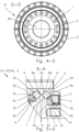
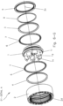
- FIG.3-G FIG.5-G Fig. 6-G a perspective exploded view of the hollow rotating body bearing arrangement of the gearbox 01 from Fig. 1-G (according to detail A in Fig. 1-G shown cross-section AA through the gearbox 01).
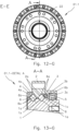
- FIG.8-G Fig. 9-G an embodiment of a gearbox 01.1 designed as a hollow shaft gearbox with hollow rotating body bearing arrangement in a section AA running along its central gearbox axis 10x, which coincides with a hollow body axis 2x, according to Fig. 12-G .
- Fig. 12-G Fig. 13-G Fig. 14-G a perspective exploded view of the hollow rotating body bearing arrangement of the gearbox 01.1 from Fig.
- FIG.15-G Fig. 17-G an embodiment of a hollow shaft gear, but without a Fig. 6-G or Fig. 14-G shown hollow rotating body bearing arrangement designed gearbox 01.2.
- Fig. 18-G an embodiment of a without a in Fig. 6-G or Fig. 14-G shown hollow rotating body bearing arrangement designed gearbox 01.3.
- Fig. 19-G Fig. 20-G Fig. 21-G Fig. 22-G Fig. 23-G Fig. 24-G Fig. 25-G Fig. 26-G Fig. 27-G Fig. 1-L an embodiment of a bearing arrangement 02 in a perspective exploded view.
- Fig. 2-L the bearing arrangement 02 from Fig. 1-L in a longitudinal section AA enclosing the hollow body axis 2x according to Fig. 5-L .
- Fig. 3-L an embodiment of a bearing arrangement 02.1 in a longitudinal section AA including the hollow body axis 2x according to Fig. 5-L .
- Fig. 4-L an embodiment of a bearing arrangement 02.2 in a longitudinal section AA including the hollow body axis 2x according to Fig. 5-L .
- Fig. 5-L the bearing arrangement 02 from Fig. 2-L , the bearing arrangement 02.1 from Fig. 3-L and the bearing arrangement 02.2 from Fig. 4-L in a side view BB according to Fig. 2-L, Fig. 3-L and Fig.
- FIG. 6-L a step-by-step process of assembling the bearing arrangement 02 from Fig. 1-L , where a) an initial state with the rotating body 1 as the bearing inner ring, Fig. 6-L b) the insertion of the support ring 3, Fig. 6-L c) the insertion of the rolling bearing elements of the first rolling bearing ring comprising rolling elements 6 and separators 7 between the support ring 3 and the rotating body 1, Fig. 6-L d) the insertion of the hollow body 2 as the bearing outer ring, Fig.
- Fig. 7-L an embodiment of a structure showing, for example, a part of a transmission 01.4 with a bearing arrangement 02.3 in a section AA according to Fig. 8-L .
- Fig. 8-L the structure showing, for example, part of a gearbox 01.4 Fig. 7-L in a side view BB according to Fig. 7-L .
- Fig. 7-L an embodiment of a structure showing, for example, a part of a transmission 01.4 with a bearing arrangement 02.3 in a section AA according to Fig. 8-L .
- Fig. 8-L the structure showing, for example, part of a gearbox 01.4 Fig. 7-L in a side view BB according to Fig. 7-L .
- Fig. 7-L an embodiment of a structure showing, for example, a part of a transmission 01.4 with a bearing arrangement 02.3 in a section AA according to Fig. 8-L .
- FIG. 9-L an embodiment of a structure showing, for example, a part of a transmission 01.5 with a bearing arrangement 02.4 in a section AA according to Fig. 10-L .
- Fig. 10-L the structure showing, for example, part of a gearbox 01.5
- Fig. 11-L an embodiment of a bearing arrangement 02.5 in a perspective exploded view.
- Fig. 12-L the bearing arrangement 02.5 from Fig. 11-L in a longitudinal section.
- Fig. 13-L an embodiment of a bearing arrangement 02.6 in a longitudinal section and in an associated side view.
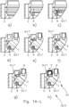
- FIG. 14-L a step-by-step process of assembling the bearing arrangement 02.5 from Fig. 11-L , where Fig. 14-L a) an initial state with the hollow body 2, Fig. 14-L b) the insertion of the support ring 4, Fig. 14-L c) the insertion of the rolling bearing elements of the first rolling bearing ring comprising rolling elements 6 and separators 7 between the support ring 4 and the hollow body 2, Fig. 14-L d) the insertion of the rotating body 1, Fig. 14-L e) the insertion of the rolling bearing elements of the second rolling bearing ring comprising rolling elements 6 and separators 7 between the hollow body 2 and the rotating body 1, Fig. 14-L f) the insertion of the support ring 3, Fig.
- FIG. 14-L g the insertion of the outer snap ring 9, and Fig. 14-L h) shows the assembly of the seal 5.
- Fig. 15-L an embodiment of a bearing arrangement 02.7 in a longitudinal section.
- Fig. 15a-L a detail of an embodiment of a bearing arrangement 02.08.
- Fig. 15b-L a detail of an embodiment of a bearing arrangement 02.09.
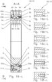
- Fig. 16-L an embodiment of a bearing arrangement 02.10 in a longitudinal section AA including the hollow body axis 2x according to Fig. 18-L.
- Fig. 16a-L a detail of a first embodiment of the bearing arrangement 02.10 from Fig. 16-L .
- Fig. 18-L the bearing arrangement 02.10 from Fig. 16-L in a side view BB according to Fig. 16-L .
- Fig. 19-L the bearing arrangement 02.11 from Fig. 17-L in a side view BB according to Fig. 17-L .
- Fig. 20-L an embodiment of a bearing arrangement 02.12 in a longitudinal section.
- Fig. 21-L an embodiment of a bearing arrangement 02.13 in a longitudinal section.
- Fig. 22-L an embodiment of a bearing arrangement 02.14 in a longitudinal section.
- Fig. 23-L an embodiment of a bearing arrangement 02.15 in a longitudinal section.
- Fig. 24-L an embodiment of a bearing arrangement 02.16 in a longitudinal section.
- FIG. 25-L an embodiment of a bearing arrangement 02.17 in a longitudinal section.
- Fig. 26-L an embodiment of a symmetrical bearing arrangement 02.18, in which the projection is provided on the inner circumference of the hollow body 2 and both support rings 3, 4 are arranged on the hollow body 2, in a longitudinal section.
- Fig. 26a)-L a representation of a Fig. 26b)-L shown intermediate assembly step before the first sequence of assembly steps for producing the bearing arrangement 02.18 from Fig. 26-L with the aid of a mounting flange 202 in a longitudinal section.
- Fig. 26b)-L a representation of the intermediate assembly step for producing the bearing arrangement 02.18 from Fig.
- FIG. 26-L with the aid of a mounting flange 202, in which intermediate assembly step the previously assembled assembly arrangement is rotated and the mounting flange 202 is then removed, in a longitudinal section.
- Fig. 26c)-L a representation of a Fig. 26b)-L shown intermediate assembly step after the following second sequence of assembly steps to complete the bearing arrangement 02.18 from Fig. 26-L after removing the mounting flange 202 in a longitudinal section.
- Fig. 27-L an embodiment of a symmetrical bearing arrangement 02.19, in which the projection is provided on the outer circumference of the rotating body 1 and both support rings 3, 4 are arranged on the rotating body 1, in a longitudinal section.
- Fig. 27a)-L a representation of a Fig.
- FIG. 27b)-L shown intermediate assembly step before the first sequence of assembly steps for producing the bearing arrangement 02.19 from Fig. 27-L with the aid of a mounting flange 203 in a longitudinal section.
- Fig. 27b)-L a representation of the intermediate assembly step for producing the bearing arrangement 02.19 from Fig. 27-L with the aid of a mounting flange 203, in which intermediate assembly step the previously assembled assembly arrangement is rotated and the mounting flange 203 is then removed, in a longitudinal section.
- Fig. 27c)-L a representation of a Fig. 27b)-L shown intermediate assembly step after the following second sequence of assembly steps to complete the bearing arrangement 02.19 from Fig. 27-L after removing the mounting flange 203 in a longitudinal section.
- the hollow rotating body bearing arrangement 02 with a hollow body 2 with a hollow body axis 2x and a rotating body 1 that can rotate about this relative to the hollow body 2 as the two bearing elements that can rotate relative to each other comprises two rolling bearing rings with oblique contact.
- the rolling bearing rings that comprise rolling bodies 6 as rolling bearing elements are arranged between the two bearing elements that can rotate relative to each other.
- the rolling bearing rings are arranged between two axial support rings 3, 4.
- the bearing arrangement referred to as a hollow rotating body bearing arrangement 02 is particularly suitable for a compact gearbox 01, 01.1, 01.4, 01.5 with two bearing elements mounted so that they can rotate relative to one another.
- the bearing elements preferably comprise a hollow body 2 with a hollow body axis 2x and a rotating body 1 mounted in the hollow body 2 so that it can rotate about the hollow body axis 2x.
- Two rolling bearing rings are arranged between the bearing elements.
- the rolling elements 6 of the two rolling bearing rings roll on two adjacent inner rolling element running surfaces 1a on the rotating body 1, which run around the hollow body axis 2x, and on two outer rolling element running surfaces 2a arranged opposite these on the hollow body 2.
- the two rolling bearing rings are separated from each other by a projection, for example a separating web.
- the two rolling bearing rings are arranged on both sides of the projection, one rolling bearing ring on each side of the projection when viewed in the axial direction along the hollow body axis twice.
- Two support rings 3, 4 are arranged on both sides of the two rolling bearing rings, one support ring 3, 4 on the side of each of the two rolling bearing rings facing away from the projection when viewed in the axial direction along the hollow body axis twice.
- the tip lies between two oppositely inclined first truncated cone surfaces of two cones whose cone axes coincide with the hollow body axis 2x, which limit the axial extension of the projection in relation to the hollow body axis 2x.
- the rolling elements (6) of one rolling bearing ring roll on each of these first truncated cone surfaces, which form, for example, inner rolling element running surfaces 1a (if the projection protrudes radially on the outer circumference of the rotating body 1) or outer rolling element running surfaces 2a (if the projection protrudes radially inwards towards the hollow body axis 2x on the inner circumference of the hollow body 2).
- each other on the remaining bearing element namely on the hollow body 2 or on the rotating body 1, depending on which body forms the first bearing element, two V-grooves are set in.
- Each of the groove walls of the two V-grooves forms one of a total of two second truncated cone surfaces opposite the first rolling element running surfaces 1a, 2a as second, outer rolling element running surfaces 2a (if the projection on the outer circumference of the rotating body 1 protrudes radially) or inner rolling element running surfaces 1a (if the projection on the inner circumference of the hollow body 2 protrudes radially inwards towards the hollow body axis 2x).
- the rolling elements 6 roll one of the two rolling bearing rings on the remaining bearing element, here the hollow body 2 or the rotating body 1, depending on which body forms the first bearing element.
- one rolling bearing ring of the two rolling bearing rings is arranged between the respective first and second or inner and outer rolling body running surfaces 1a, 2a, one rolling bearing ring on each side.
- a support ring 3, 4 is arranged which holds the rolling bearing elements 6, 7 of the rolling bearing rings in their positions on the rolling body running surfaces 1a, 2a, one support ring 3, 4 on each side of the rolling bearing rings facing away from the projection.
- the support rings 3, 4 each have a truncated cone-shaped support surface 3b, 4b on their end faces facing the projection.
- Each support surface 3b, 4b forms the groove walls of two two-part V-(fillet) grooves together with a first, inner rolling element running surface 1a (if the projection is arranged on the rotating body 1 and thus the first rolling element running surfaces 1a are also formed on the rotating body 1) or outer rolling element running surface 2a (if the projection is arranged on the hollow body 2 and thus the first rolling element running surfaces 2a are also formed on the hollow body 2).
- the two rolling bearing rings are arranged in two pairs of grooves spaced 2x apart along the hollow body axis
- Each pair of grooves consists of a groove delimited by two groove walls on one bearing element and an opposite groove, also delimited by two groove walls, on the remaining bearing element.
- One groove wall of each groove is designed as a rolling element running surface 1a, 2a, the remaining groove wall as an inner or outer rolling element support surface 1b, 2b.
- each rolling element running surface 1a, 2a borders on both sides on a rolling element support surface 1b, 2b, 3b, 4b and vice versa.
- the rolling element running surfaces 1a, 2a are thus arranged opposite one another, just as the rolling element support surfaces 1b, 2b, 3b, 4b are arranged opposite one another.
- Each rolling bearing ring preferably consists of rolling bearing elements comprising, for example, alternating rolling elements 6 and separators 7.
- An annular gap remains between the two bearing elements in order to ensure their relative rotatability.
- a radial projection is formed which is delimited in the axial direction with respect to the hollow body axis 2x by two preferably immediately adjacent first truncated cone surfaces which are axially offset relative to one another with respect to the hollow body axis 2x and arranged inclined in opposite directions, with a tip projecting into the annular gap towards the opposite bearing element, in which the two first truncated cone surfaces are directly adjacent to one another, on each of these first truncated cone surfaces forming inner or outer rolling element running surfaces 1a, 2a as explained above, the rolling elements 6 of a rolling bearing ring of two axially spaced rolling bearing rings made up of rolling bearing elements comprising, for example, alternating rolling elements 6 and separators 7 roll.
- the radial projection has on its two axial flanks the two first truncated cone surfaces which form the two first, inner or outer rolling element running surfaces 1a, 2a on which the rolling elements 6 of the two rolling bearing rings roll on the one bearing element.
- two V-grooves are set in along the hollow body axis, spaced apart 2x axially from each other.
- one of the groove walls forms one of a total of two second truncated cone surfaces opposite the first rolling element running surfaces 1a, 2a as second, outer or inner rolling element running surfaces 2a, 1a, as described above.
- the rolling elements 6 roll one of the two Rolling bearing rings on the remaining bearing element.
- each V-groove merely forms a truncated cone-shaped second rolling element support surface 1b, 2b, which prevents the rolling elements 6 of the respective rolling bearing ring from sliding off the respective second rolling element running surface 2a, 1a transversely to their rolling movement.
- one rolling bearing ring of each of the two rolling bearing rings is arranged between the respective first and second rolling element running surfaces 1a, 2a, one rolling bearing ring on each side.
- a support ring 3, 4 is arranged to hold the rolling bearing elements of the rolling bearing rings in their positions on the rolling element running surfaces 1a, 2a, one support ring 3, 4 on each side of the two rolling bearing rings facing away from the projection.
- the support rings 3, 4 each have a support surface 3b, 4b in the form of a truncated cone, which complements the first truncated cone surfaces forming the first rolling element running surfaces 1a, 2a formed on both sides of the projection in the axial direction to form a V-groove (fillet) groove.
- each support surface 3b, 4b together with a first rolling element running surface 1a, 2a forms the groove walls of a two-part V-groove (fillet) groove.
- Each of the two support surfaces 3b, 4b formed on the support rings 3, 4 serves only as a frustoconical surface-shaped first rolling element support surface, which prevents the rolling elements 6 of the respective rolling bearing ring from sliding off the first rolling element running surface 1a, 2a of the projection adjacent to the respective support ring 3, 4, transversely to their rolling movement.
- the support surfaces 3b, 4b project beyond the first rolling element running surfaces 1a, 2a normal to the hollow body axis 2x to a degree sufficient to hold the rolling bearing elements in axial position.
- the support rings 3, 4 thus protrude laterally from the rolling bearing elements of the rolling bearing rings partially into the annular gap between the hollow body 2 and the rotating body 1, for example up to half.
- the hollow rotating body bearing arrangement 02 can therefore be described as a bearing arrangement for a compactly constructed transmission 01, 01.1, 01.2, 01.4, 01.5 with two bearing elements arranged so as to rotate relative to one another.
- the bearing elements are preferably a hollow body 2 with a hollow body axis 2x and a rotating body 1 mounted in the hollow body 2 so as to rotate about the hollow body axis 2x.
- the hollow rotating body bearing arrangement 02 comprises the hollow body 2 and the rotating body 1 mounted in the hollow body 2 so as to rotate about the hollow body axis 2x as its bearing elements.
- Two rolling bearing rings made of rolling bearing elements comprising, for example, alternating rolling bodies 6 and separators 7 are arranged between the hollow body 2 and the rotating body 1.
- the two rolling bearing rings are at least partially housed in two pairs of bearing grooves between the hollow body 2 and the rotating body 1, which are spaced apart from one another along the hollow body axis 2x.
- This restriction relates, for example, to the fact that at least one annular gap must remain between the hollow body 2 and the rotating body 1 so that the latter can rotate relative to the former.
- the bearing grooves on the hollow body side each have an outer rolling element running surface 2a inclined to the hollow body axis 2x.
- the outer rolling element running surfaces 2a are located on the lateral surfaces of two straight circular cones arranged opposite one another along the hollow body axis 2a.
- the outer rolling element running surfaces 2a are arranged inclined to one another in opposite directions at an angle.
- the angle of the hollow body side bearing grooves enclosed between the outer rolling element running surfaces 2a is, for example, 75° to 105°.
- the bearing grooves on the rotating body side are arranged opposite the bearing grooves on the hollow body side. Analogous to the outer rolling element running surfaces 2a, the bearing grooves on the rotating body side each have an inner rolling element running surface 1a inclined 2x to the hollow body axis.
- the inner rolling element running surfaces 1a are located on the lateral surfaces of two straight circular cones arranged in reverse direction along the hollow body axis 2x compared to the outer rolling element running surfaces 2a. Each of the two inner rolling element running surfaces 2a is arranged opposite an outer rolling element running surface 1a. The inner rolling element running surfaces 1a are also arranged inclined in opposite directions at an angle to the hollow body axis 2x. The included angle between the inner rolling element running surfaces 1a of the hollow body-side bearing grooves is, for example, 105° to 75°.
- the rolling element running surfaces 2a of the hollow body-side bearing grooves or the rolling element running surfaces 1a of the rotating body-side bearing grooves can be arranged directly adjacent to one another. These limit the previously mentioned projection.
- the projection on the hollow body 2 is arranged to project inwards when the rolling element running surfaces 2a of the bearing grooves on the hollow body side are arranged directly adjacent to one another.
- the projection on the rotating body 1 is arranged to project outwards when the rolling element running surfaces 1a of the bearing grooves on the rotating body side are arranged directly adjacent to one another.
- the rolling element running surfaces 1a, 2a of the remaining bearing grooves are arranged at a distance from one another.
- Their remaining bearing groove walls can be designed as support surfaces 1b, 2b.
- Bearing groove walls designed as support surfaces 1b, 2b are directly adjacent to the rolling element running surfaces 1a, 2a formed on the same bearing element.
- the support surfaces 1b, 2b guide the rolling elements 6 of the rolling bearing rings rolling on the rolling element running surfaces 1a, 2a formed on the same bearing element on their end faces 6b.
- the rolling element running surfaces 1a, 2a each correspond to the surface area of a truncated cone.
- the truncated cones whose lateral surfaces form the outer rolling element running surfaces 2a, have a base surface with the outer diameter of the outer rolling element running surfaces 2a and a cover surface with the inner diameter of the outer rolling element running surfaces 2a.
- the truncated cones whose lateral surfaces form the inner rolling element running surfaces 1a, have a base surface with the outer diameter of the inner rolling element running surfaces 1a and a cover surface with the inner diameter of the inner rolling element running surfaces 1a.
- the bearing groove walls which are the furthest apart from one another in the axial direction along the hollow body axis 2x and which delimit the bearing grooves with the directly adjacent, oppositely inclined rolling element running surfaces 1a, 2a are located on two support rings 3, 4 arranged on both sides of the rolling bearing rings.
- the rolling element axes of the rolling elements 6 of the two rolling bearing rings of the hollow rotating body bearing arrangement 02 intersect the hollow body axis 2x.
- the hollow rotating body bearing arrangement 02 can be designed for a transmission 01, 01.1 designed as a cycloidal transmission with at least one cycloidal disk 16, 17 rolling in the hollow body 2 or in a transmission housing 10 and arranged on an eccentric section 13e, 36f of at least one cycloidal disk rotatable about an eccentric shaft 13, 36 running parallel to the hollow body axis 2x.
- the projection can be arranged on the inner circumference of the hollow body 2. In this case, it projects radially inwards and is limited by two outer rolling element running surfaces 2a in the axial direction along the hollow body axis 2x.
- the V-grooves (fillet) having the inner rolling element running surfaces 1a as the first groove wall and the two immediately adjacent support surfaces 1b as the remaining groove wall are arranged on the rotating body 1.
- the projection can alternatively be arranged on the outer circumference of the rotating body 1. In this case, it projects radially outwards and is limited by two inner rolling element running surfaces 1a in the axial direction along the hollow body axis 2x.
- the V-grooves (fillet) having the outer rolling element running surfaces 2a as the first groove wall and the two immediately adjacent support surfaces 2b as the remaining groove wall are arranged on the hollow body 2.
- Each rolling bearing ring of the hollow rotating body bearing arrangement 02 can consist of rolling bearing elements comprising alternating rolling elements 6 and separators 7.
- the support rings 3, 4 can both be arranged on the hollow body 2 or both on the rotating body 1.
- one support ring 3, 4 can alternatively be arranged on the hollow body 2 and the other support ring 4, 3 on the rotating body 1.
- the projection in the axial direction and the first rolling element running surfaces 1a, 2a are axially arranged relative to each other with respect to the hollow body axis 2x offset and inclined in opposite directions first truncated cone surfaces immediately adjacent at an included angle of 75° to 105°.
- the rolling elements 6 of at least one rolling bearing ring can be designed as cylindrical rollers.
- the first, for example inner or outer rolling element running surfaces 1a, 2a and the second, for example outer or inner rolling element running surfaces 2a, 1a assigned to the same rolling bearing ring run parallel to one another.
- the rolling elements 6 of at least one rolling bearing ring can be designed as tapered rollers.
- the first, for example inner or outer rolling element running surfaces 1a, 2a and the second, for example inner or outer rolling element running surfaces 2a, 1a, each assigned to the same rolling bearing ring enclose an angle corresponding to the opening angle of the supplementary cone to the truncated cone of the tapered rollers.
- the rolling elements can be designed as cylindrical or tapered rollers. Accordingly, the first rolling element running surfaces and second rolling element running surfaces assigned to the same rolling bearing ring run parallel to one another, or they enclose an angle corresponding to the opening angle of the supplementary cone to the truncated cone of the tapered rollers.
- V-grooves of the hollow rotating body bearing arrangement 02 each span surfaces on which the cylinder or hollow body axis rests twice normally.
- the hollow rotating body bearing arrangement 02 can be integrated into various construction devices, as shown in the drawings Fig. 1-G , Fig. 5-G , Fig. 6-G , Fig. 8-G, Fig. 9-G , Fig. 13-G , Fig. 14-G , Fig. 15-G as well as in the Fig. 7-L until Fig. 10-L shown in whole or in part gears 01, 01.1 and structures 01.4 and 01.5 as examples.
- the structure of a Fig. 1-L and Fig. 2-L shown hollow rotating body bearing arrangement 02 with two rolling bearing rings with oblique contact is characterized by the fact that its structure contains additional support rings 3, 4, which are designed free of rolling element running surfaces.
- the hollow rotating body bearing arrangement 02 enables clear and simplified assembly with rolling bearing elements as a whole, for example, comprising rolling elements 6 and separators 7.
- Fig. 6-L a) until G) and in Fig. 14-L a) to h) is a step-by-step assembly of a hollow rotating body bearing arrangement 02 ( Fig. 6-L ) and 02.5 ( Fig. 14-L )
- the assembly of the hollow rotating body bearing arrangement 02 according to the invention prevents orientation errors of the rolling elements 6 and of the separators 7 that may be arranged between the rolling elements 6, for example designed as separating webs.
- rolling elements such as rolling elements 6 and separators 7, which is located on the side of the additional support ring 4 ( Fig. 1-L until Fig. 8-L , Fig. 11-L until Fig. 15-L , Fig. Fig. 20-L until Fig. 27-L, Fig. 26c)-L and Fig. 27c)-L ).
- the projection which is delimited on both sides by rolling element running surfaces 2a when viewed in the axial direction parallel to the hollow body axis 2x, is provided on the inner circumference of the hollow body 2.
- the bearing arrangement 02 comprises rolling element running surfaces 2a on the hollow body 2, which are formed at an angle of 45°.
- the rolling elements 6 on the hollow body 2 roll on the rolling element running surfaces 2a.
- the bearing arrangement 02 also comprises rolling element running surfaces 1 on the rotating body 1, which are formed at an angle of 45°.
- the rolling elements 6 on the rotating body 1 roll on the rolling element running surfaces 1a.
- the end faces 6b of the rolling elements 6 are guided during rolling by support surfaces 1b on the rotating body 1 and by support surfaces 3b, 4b formed on the support rings 3, 4.
- the support surfaces 3b and 4b complement the two rolling element running surfaces 1a on the rotating body 1 to form two-part V-grooves.
- the support rings 3, 4 therefore advantageously only have an increased surface hardness on their support surfaces 3b, 4b oriented in a direction perpendicular to the rolling direction of the rolling elements 6 and coming into contact with the end faces 6b of the rolling elements 6.
- the support rings 3, 4 have neither rolling element running surfaces nor are they subject to high requirements in terms of fitting accuracy. Their manufacture therefore requires sufficient material and heat treatment or sufficient manufacturing accuracy, which is much simpler and more cost-effective than the manufacture of full-fledged classic bearing rings.
- the support ring 3 has a surface 3c for its alignment with respect to a seat 1c on the rotating body 1.
- the support ring 4 can have a surface 4c for its alignment with a seat 1c on the rotating body 1.
- the support rings 3, 4 only require an appropriate fit in relation to the respective seat 1c on the rotating body.
- the bearing arrangement 02 shown can have at least one seal 5 between the rotating body 1 forming an outer bearing ring, also referred to as the bearing outer ring, and the hollow body 2 forming an inner bearing ring, also referred to as the bearing inner ring.
- the bearing arrangement 02 shown can be removed after removing the seal 5 in the reverse order as in Fig. 6-L shown, starting with the support ring 4 and the adjacent rolling bearing ring.
- the support ring 4 has a surface 4c for its alignment with respect to a seat 2c formed on the hollow body 2.
- the support ring 4 is secured by an inner snap ring 8 engaging in a groove on the inner circumference of the hollow body 2.
- the bearing arrangement 02.02 shown has rolling bearing rings with tapered rollers 66 instead of cylindrical rolling elements 6. Accordingly, the rolling element running surfaces 1a and 2a, which are opposite one another on the rotating body 1 and on the hollow body 2 and are assigned to the same rolling bearing ring with tapered rollers 66, do not run parallel to one another. Instead, the surfaces spanned by the rolling element running surfaces 1a and 2a, which are opposite one another, intersect. The rolling element running surfaces 1a and 2a, which are opposite one another, enclose an angle between them.
- An O-ring 121 can be used to seal the connection between flange 101 and rotating body 1.
- the projection which is delimited on both sides by rolling element running surfaces 1a when viewed in the axial direction parallel to the hollow body axis 2x, is provided on the outer circumference of the rotating body 1.
- the bearing arrangement 02.5 has rolling element running surfaces 1a formed at an angle of 45° on the rotating body 1 forming the inner bearing ring and rolling element running surfaces 2a opposite these and also inclined by 45° on the hollow body 2 forming the bearing outer ring.
- the rolling elements 6 each roll on one of the two rolling bearing rings on a running surface pair consisting of a rolling element running surface 1a on the rotating body 1 and a rolling element running surface 2a opposite this on the hollow body 2.
- the rolling elements 6 are guided on one of their end faces 6b by support surfaces 2b on the hollow body.
- the rolling elements 6 of one rolling bearing ring are guided by support surfaces 3b arranged on one support ring 3, and the rolling elements 6 of the other rolling bearing ring are guided by support surfaces 4b arranged on the other support ring 4.
- a surface 3c is advantageously formed on the support ring 3, with which it is arranged on a seat 1c formed on the rotating body 1.
- a snap ring 9 can serve to axially secure the support ring 3.
- the support surfaces 3b and 4b complement the two rolling element running surfaces 2a on the hollow body 2 to form two-part V-grooves (fillet) grooves.
- the sequence of assembling the bearing arrangement 02.5 from Fig. 11-L and Fig. 12-L is in Fig. 14-L Step-by-step starting with Fig. 14-L a) and ending with Fig. 14-L h)
- the optically clear and thus easier to control, automate and simplify assembly ensures good accessibility for inserting the rolling elements 6 and, if necessary, separators 7 designed as separating webs, for example, as rolling bearing elements of the two rolling bearing rings arranged between the rotating body 1 and the hollow body 2 and secured in the axial direction by the two support rings 3, 4.
- a seal 5 can optionally be installed. Feed holes are not required.
- the rolling bearing rings can be inserted in one piece.
- the hollow body 2 can be provided with an internal toothing formed by grooves 2d, or can be prepared for an internal toothing by incorporating grooves 2d suitable for the insertion of rolling elements 18 serving as teeth. This can be advantageous for use in machines, for example.
- rolling element running surfaces 2a and adjacent support surfaces 2b for the end faces 6b of the rolling elements 6 oriented towards the hollow body are formed on the inner circumference of the hollow body 2.
- Support surfaces 3b, 4b for the end faces 6b of the rolling elements 6 oriented towards the rotating body are formed on the support rings 3, 4.
- a surface 3c is formed on the outer circumference of the support ring 3, with which the support ring 3 is arranged on a seat 2c on the hollow body 2.
- the support ring 4 has a surface 4c formed on its inner circumference, with which it is arranged on a seat 1c on the rotating body 1.
- the support rings 3, 4 can be pressed, glued or plugged onto the respective seat 1c, 2c.
- the support rings 3, 4 in the construction of the device into which the bearing arrangement 02.7 is intended for installation can be secured against axial movement in order to guide the rolling elements 6 at their end faces 6b with their support surfaces 3b, 4b.
- the support ring 4 has the surface 4c on its inner circumference, with which it is arranged on a seat 1c on the rotating body 1.
- the support ring 4 is secured against slipping in the axial direction parallel to the hollow body axis 2x with connecting means designed, for example, as screws 110.
- the support ring 4 is secured with a snap ring 9 against slipping in the axial direction parallel to the hollow body axis 2x.
- a Fig. 16-L In the bearing arrangement 02.10 shown, the projection in the axial direction parallel to the hollow body axis 2x is limited by the rolling element running surfaces 2a inclined by 45° in opposite directions, again on the inner circumference of the hollow body 2 is provided.
- a support ring 3 is formed on its inner circumference with a surface 3c, with which it is arranged on a seat 1c on the rotating body 1.
- On the support ring 3 is a rolling element 6 of the Fig. 16-L right rolling bearing ring on its end faces 6b facing the hollow body 2.
- the support ring 44 which is provided with a support surface 44b leading to the left rolling bearing ring, is arranged on the front side of the hollow body 2.
- the support ring 44 can be attached to the front of the hollow body 2 with connecting means comprising, for example, screws 114.
- An O-ring 122 can be inserted to seal the connection between the hollow body 2 and the support ring 44.
- the bearing arrangement 02.10 can be designed to be completely sealed, for example by arranging a seal 55a between the support ring 44 and the rotating body 1 and a seal 55b between the hollow body 2 and the rotating body 1 in addition to the O-ring 122 arranged between the support ring 44 and the hollow body 2.
- the support ring 44 and the hollow body 2 can have holes 44e, 2e, which can be provided to fix the bearing arrangement 02.10 as a whole with connecting means, for example comprising screws, during its installation in a device which, for example, forms part of a transmission or completely or partially comprises a transmission.
- the bearing arrangement 02.10 can alternatively or additionally have holes 1e on the rotating body 1, which can be provided to fix the bearing arrangement 02.10 as a whole with connecting means comprising, for example, screws during its installation in a device which, for example, forms part of a transmission or completely or partially comprises a transmission.
- a lubrication hole 2f can be arranged, for example, on the hollow body 2 and/or on the rotating body 1 in order to lubricate the rolling bearing rings as in the Fig. 16-L to be able to supply the bearing arrangement 02.10 shown with lubricant or to fill the annular gap remaining between the rotating body 1 and the hollow body 2 with lubricant.
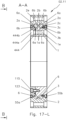
- a Fig. 17-L In the bearing arrangement 02.11 shown, the projection, which is limited in the axial direction parallel to the hollow body axis 2x by the rolling element running surfaces 1a inclined by 45° in opposite directions, is again provided on the outer circumference of the rotating body 1.
- a support ring 3 is formed on its outer circumference with a surface 3c, with which it is arranged on a seat 2c on the hollow body 2.
- On the support ring 3 is a rolling element 6 of the Fig. 17-L right rolling bearing ring on its end faces 6b facing the rotating body 1.
- the support ring 444 which is provided with a support surface 444b leading to the left rolling bearing ring, is arranged on the front side of the rotating body 1.
- the support ring 444 can be fastened to the front side of the rotating body 1 with connecting means, for example comprising screws 115.
- An O-ring 123 can serve to seal the connection between the support ring 444 and the rotating body 1.
- seals 55a, 55b may be provided, a seal 55a between the support ring 444 and the hollow body 2 and/or a seal 55b between the hollow body 2 and the rotating body 1.
- the hollow body 2 and/or the support ring 444 and/or the rotating body 1 can have holes 2e, 444e and 1e, which can be provided for connecting the bearing arrangement 02.11 as a whole with, for example, connecting means comprising screws during their installation in a device which, for example, forms part of a transmission or completely or partially comprises a transmission.
- seals 55a, 55b are arranged on both sides of the rolling bearing rings outside the support rings 3, 4 between the rotating body 1 and the hollow body 2.
- the axial position of the support ring 4 can be secured by a snap ring 9 fixed to the outer circumference of the rotating body 1.
- the axial position of the support ring 3 can be secured by a snap ring 8 fixed to the inner circumference of the hollow body 2.
- the hollow body 2 can be provided with an external toothing 2z.
- the rotating body 1 can alternatively or additionally be provided with an internal toothing 1d.
- the in Fig. 21-L The bearing arrangement 02.13 shown is not sealed and is intended for installation in devices.
- the rotating body 1 can be provided with an external toothing 1z.
- the external toothing 1z can be designed as a spline.
- the support ring 3 arranged on the hollow body 2 can be secured by a flange 200 abutting the front of the hollow body 2, for example a device that completely or partially encloses a gear.
- the support ring 4 can be axially secured by the shape of the outer circumference of the rotating body 1.
- the projection is arranged on the outer circumference of the rotating body 1.
- the rolling body axes indicated by solid lines therefore intersect radially outside the rotating body 1, whereas they intersect in the rotating body 1 when the projection is arranged on the inner circumference of the hollow body 2.
- the support ring 4 can be axially secured by the shape on the inner circumference of the hollow body 2.
- the axial position of the support ring 3 can be secured by a snap ring 9 arranged on the outer circumference of the rotating body 1.
- the bearing arrangement 02.15 shown in Fig. 24-L The bearing arrangement 02.16 shown is not sealed and is therefore intended for installation in devices.
- the support ring 3 arranged on the rotating body 1 can be replaced by a 1 arranged flange 201.
- the hollow body 2 can be provided with an internal toothing formed by grooves 2d, or can be prepared for an internal toothing by incorporating grooves 2d suitable for the insertion of rolling elements 18 serving as teeth.
- the projection is arranged on the inner circumference of the hollow body 2.
- the support rings 3, 4 are each designed with a surface 3c, 4c, for example produced as a fit, with which surfaces 3c, 4c they are both arranged on a seat 2c, for example also designed as a fit, on the inner circumference of the hollow body 2.
- the bearing arrangement 02.18 is therefore characterized by a symmetrical structure, in which both support rings 3, 4 are arranged on the hollow body 2.
- the support rings can be axially secured with snap rings 8 inserted in grooves on the inner circumference of the hollow body 2. Seals 55 can be provided on both sides outside the snap rings 8 in the axial direction to seal the annular gap remaining between the hollow body 2 and the rotating body 1.
- the in Fig. 27-L The bearing arrangement 02.19 shown can also have a symmetrical structure with the same design of the support rings 3, 4 and the seals 55 inserted between the ring gear 2 and the rotating body 1.
- the bearing arrangement 02.19 shown in Fig. 26-L shown and in a sequence of their assembly in Fig. 26a)-L to Fig. 26c)-L In the bearing arrangement 02.18 shown, in the bearing arrangement 02.19 the projection is again arranged on the outer circumference of the rotating body 1.
- the support ring 3 is arranged with the surface 3c designed as a fit on the seat 1c on the rotating body 1, which is also designed as a fit.
- the axial position of the support rings 3 and 4 is secured by the snap rings 9 inserted in grooves on the outer circumference of the rotating body 1.
- the axial position of the support rings 3 and 4 is advantageously ensured by the design of the rotating body 1.
- a mounting flange 203 is used for its assembly, into which the hollow body 2 forming the outer bearing ring is inserted before assembly.
- the rolling elements 6 and separators 7 of the first rolling bearing ring are then inserted.
- the rotating body 1 forming the inner bearing ring is then inserted.
- the rolling elements 6 and separators 7 of the second rolling bearing ring are then inserted.
- the support ring 3, the adjacent outer snap ring 9 and the seal 55 are then inserted in sequence.
- the subject matter of the invention relating to the hollow rotary body bearing arrangements 02 can alternatively be implemented by a gear 01, 01.1, 01.4, 01.5 designed as a cycloidal gear with a hollow body 2 with a hollow body axis 2x and a rotary body 1 arranged relative to the hollow body axis 2x so as to be rotatable and with a preceding described hollow rotating body bearing arrangement 02 which supports the rotating body 1 rotatably relative to the hollow body 2.
- the described hollow rotary body bearing arrangements 02 can have individual features or a combination of the features previously described and/or listed in the following claims in connection with a transmission 01, 01.1, just as the described transmissions 01, 01.1 can have individual features or a combination of several features previously described and/or listed in the following claims in connection with a hollow rotary body bearing arrangement 02.
- the invention is particularly applicable commercially in the field of manufacturing compact gears, in particular precision gears, in particular gears comprising cycloidal gears.
Landscapes
- Engineering & Computer Science (AREA)
- General Engineering & Computer Science (AREA)
- Mechanical Engineering (AREA)
- Rolling Contact Bearings (AREA)
Priority Applications (2)
| Application Number | Priority Date | Filing Date | Title |
|---|---|---|---|
| EP23166360.0A EP4443013A1 (fr) | 2023-04-03 | 2023-04-03 | Ensemble palier pour transmission |
| PCT/EP2024/058118 WO2024208665A1 (fr) | 2023-04-03 | 2024-03-26 | Agencement de palier pour une transmission |
Applications Claiming Priority (1)
| Application Number | Priority Date | Filing Date | Title |
|---|---|---|---|
| EP23166360.0A EP4443013A1 (fr) | 2023-04-03 | 2023-04-03 | Ensemble palier pour transmission |
Publications (1)
| Publication Number | Publication Date |
|---|---|
| EP4443013A1 true EP4443013A1 (fr) | 2024-10-09 |
Family
ID=85800226
Family Applications (1)
| Application Number | Title | Priority Date | Filing Date |
|---|---|---|---|
| EP23166360.0A Withdrawn EP4443013A1 (fr) | 2023-04-03 | 2023-04-03 | Ensemble palier pour transmission |
Country Status (2)
| Country | Link |
|---|---|
| EP (1) | EP4443013A1 (fr) |
| WO (1) | WO2024208665A1 (fr) |
Citations (4)
| Publication number | Priority date | Publication date | Assignee | Title |
|---|---|---|---|---|
| US4906113A (en) * | 1988-07-27 | 1990-03-06 | Quintette Coal Limited | Slew ring bearing |
| DE102010054948A1 (de) * | 2010-12-17 | 2012-06-21 | Schaeffler Technologies Gmbh & Co. Kg | Lageranordnung |
| DE102016223574A1 (de) * | 2016-11-28 | 2018-05-30 | Minebea Mitsumi Inc. | Wälzlager |
| WO2019096723A1 (fr) | 2017-11-14 | 2019-05-23 | Kimex Group s.r.o. | Transmission |
Family Cites Families (5)
| Publication number | Priority date | Publication date | Assignee | Title |
|---|---|---|---|---|
| GB1453327A (en) | 1974-02-04 | 1976-10-20 | Priestman Bros Ltd | Roller bearings |
| JP3032054B2 (ja) | 1991-08-19 | 2000-04-10 | 日本トムソン株式会社 | アンギュラコンタクト円筒ころ軸受 |
| JP4253069B2 (ja) | 1999-04-30 | 2009-04-08 | 日本トムソン株式会社 | アンギュラコンタクト円筒ころ軸受 |
| FR3003615B1 (fr) | 2013-03-25 | 2015-07-17 | Skf Ab | Palier a roulement comprenant au moins une bague en plusieurs parties, notamment pour eolienne, et procede de montage associe |
| US9188161B2 (en) | 2014-03-25 | 2015-11-17 | Aktiebolaget Skf | Rolling bearing comprising at least one multipart ring, notably for a wind turbine, and associated mounting method |
-
2023
- 2023-04-03 EP EP23166360.0A patent/EP4443013A1/fr not_active Withdrawn
-
2024
- 2024-03-26 WO PCT/EP2024/058118 patent/WO2024208665A1/fr not_active Ceased
Patent Citations (4)
| Publication number | Priority date | Publication date | Assignee | Title |
|---|---|---|---|---|
| US4906113A (en) * | 1988-07-27 | 1990-03-06 | Quintette Coal Limited | Slew ring bearing |
| DE102010054948A1 (de) * | 2010-12-17 | 2012-06-21 | Schaeffler Technologies Gmbh & Co. Kg | Lageranordnung |
| DE102016223574A1 (de) * | 2016-11-28 | 2018-05-30 | Minebea Mitsumi Inc. | Wälzlager |
| WO2019096723A1 (fr) | 2017-11-14 | 2019-05-23 | Kimex Group s.r.o. | Transmission |
Also Published As
| Publication number | Publication date |
|---|---|
| WO2024208665A1 (fr) | 2024-10-10 |
Similar Documents
| Publication | Publication Date | Title |
|---|---|---|
| EP3290751B1 (fr) | Train épicycloïdal | |
| EP1567786B1 (fr) | Procede de transmission de couple a faibles pertes dans les boites a engrenages planetaires | |
| DE69426448T2 (de) | Zylindrisches zahnrad für ausseren zahneingriff | |
| EP0854987B1 (fr) | Boíte de vitesses et palier pour la même | |
| DE102013002314B4 (de) | Untersetzungsgetriebe der exzentrisch umlaufenden Bauart | |
| DE19833436A1 (de) | Nabeneinheit-Komplettlager und Verfahren zur Herstellung desselben | |
| DE69408425T2 (de) | Planetengetriebe mit Lastverteilung | |
| DE3530558C2 (fr) | ||
| DE102012210169A1 (de) | Exzentergetriebe | |
| DE112004002814B4 (de) | Zusammengesetztes Wälzlager | |
| EP0049903B1 (fr) | Mécanisme à vis et écrou avec double écrou | |
| DE69515181T2 (de) | Exzentergetriebe | |
| DE102020109646B4 (de) | Drehlager und Getriebebox | |
| DE19544197A1 (de) | Planetengetriebe | |
| DE2458399A1 (de) | Universalfraeskopf | |
| DE102008046821B4 (de) | Kurbelwelle für eine Brennkraftmaschine mit varibaler Verdichtung und Brennkraftmaschine mit variabler Verdichtung | |
| DE102004058551B4 (de) | Getriebe | |
| DE102023108493A1 (de) | Lageranordnung für Getriebe | |
| DE3418621A1 (de) | Waelzlager | |
| WO2024208665A1 (fr) | Agencement de palier pour une transmission | |
| DE4419432C2 (de) | Zykloidengetriebe | |
| EP4136365B1 (fr) | Boîte de vitesses | |
| DE3141563A1 (de) | "antriebseinheit, insb. winkelgetriebe" | |
| DE19824069A1 (de) | Getriebe | |
| EP4443017A1 (fr) | Transmission |
Legal Events
| Date | Code | Title | Description |
|---|---|---|---|
| PUAI | Public reference made under article 153(3) epc to a published international application that has entered the european phase |
Free format text: ORIGINAL CODE: 0009012 |
|
| STAA | Information on the status of an ep patent application or granted ep patent |
Free format text: STATUS: THE APPLICATION HAS BEEN PUBLISHED |
|
| STAA | Information on the status of an ep patent application or granted ep patent |
Free format text: STATUS: THE APPLICATION HAS BEEN WITHDRAWN |
|
| AK | Designated contracting states |
Kind code of ref document: A1 Designated state(s): AL AT BE BG CH CY CZ DE DK EE ES FI FR GB GR HR HU IE IS IT LI LT LU LV MC ME MK MT NL NO PL PT RO RS SE SI SK SM TR |
|
| 18W | Application withdrawn |
Effective date: 20241001 |