EP4443103A1 - Méthode optique pour la mesure non destructive de l'épaisseur d'un contenant creux - Google Patents
Méthode optique pour la mesure non destructive de l'épaisseur d'un contenant creux Download PDFInfo
- Publication number
- EP4443103A1 EP4443103A1 EP24167181.7A EP24167181A EP4443103A1 EP 4443103 A1 EP4443103 A1 EP 4443103A1 EP 24167181 A EP24167181 A EP 24167181A EP 4443103 A1 EP4443103 A1 EP 4443103A1
- Authority
- EP
- European Patent Office
- Prior art keywords
- article
- image
- thickness
- light radiation
- radiation
- Prior art date
- Legal status (The legal status is an assumption and is not a legal conclusion. Google has not performed a legal analysis and makes no representation as to the accuracy of the status listed.)
- Granted
Links
Images


Classifications
-
- G—PHYSICS
- G01—MEASURING; TESTING
- G01B—MEASURING LENGTH, THICKNESS OR SIMILAR LINEAR DIMENSIONS; MEASURING ANGLES; MEASURING AREAS; MEASURING IRREGULARITIES OF SURFACES OR CONTOURS
- G01B11/00—Measuring arrangements characterised by the use of optical techniques
- G01B11/02—Measuring arrangements characterised by the use of optical techniques for measuring length, width or thickness
- G01B11/06—Measuring arrangements characterised by the use of optical techniques for measuring length, width or thickness for measuring thickness ; e.g. of sheet material
-
- B—PERFORMING OPERATIONS; TRANSPORTING
- B07—SEPARATING SOLIDS FROM SOLIDS; SORTING
- B07C—POSTAL SORTING; SORTING INDIVIDUAL ARTICLES, OR BULK MATERIAL FIT TO BE SORTED PIECE-MEAL, e.g. BY PICKING
- B07C5/00—Sorting according to a characteristic or feature of the articles or material being sorted, e.g. by control effected by devices which detect or measure such characteristic or feature; Sorting by manually actuated devices, e.g. switches
- B07C5/34—Sorting according to other particular properties
- B07C5/3404—Sorting according to other particular properties according to properties of containers or receptacles, e.g. rigidity, leaks, fill-level
- B07C5/3408—Sorting according to other particular properties according to properties of containers or receptacles, e.g. rigidity, leaks, fill-level for bottles, jars or other glassware
-
- G—PHYSICS
- G01—MEASURING; TESTING
- G01B—MEASURING LENGTH, THICKNESS OR SIMILAR LINEAR DIMENSIONS; MEASURING ANGLES; MEASURING AREAS; MEASURING IRREGULARITIES OF SURFACES OR CONTOURS
- G01B11/00—Measuring arrangements characterised by the use of optical techniques
- G01B11/08—Measuring arrangements characterised by the use of optical techniques for measuring diameters
- G01B11/10—Measuring arrangements characterised by the use of optical techniques for measuring diameters of objects while moving
-
- G—PHYSICS
- G01—MEASURING; TESTING
- G01B—MEASURING LENGTH, THICKNESS OR SIMILAR LINEAR DIMENSIONS; MEASURING ANGLES; MEASURING AREAS; MEASURING IRREGULARITIES OF SURFACES OR CONTOURS
- G01B11/00—Measuring arrangements characterised by the use of optical techniques
- G01B11/08—Measuring arrangements characterised by the use of optical techniques for measuring diameters
- G01B11/12—Measuring arrangements characterised by the use of optical techniques for measuring diameters internal diameters
-
- G—PHYSICS
- G01—MEASURING; TESTING
- G01B—MEASURING LENGTH, THICKNESS OR SIMILAR LINEAR DIMENSIONS; MEASURING ANGLES; MEASURING AREAS; MEASURING IRREGULARITIES OF SURFACES OR CONTOURS
- G01B11/00—Measuring arrangements characterised by the use of optical techniques
- G01B11/26—Measuring arrangements characterised by the use of optical techniques for measuring angles or tapers; for testing the alignment of axes
- G01B11/27—Measuring arrangements characterised by the use of optical techniques for measuring angles or tapers; for testing the alignment of axes for testing the alignment of axes
-
- G—PHYSICS
- G01—MEASURING; TESTING
- G01N—INVESTIGATING OR ANALYSING MATERIALS BY DETERMINING THEIR CHEMICAL OR PHYSICAL PROPERTIES
- G01N21/00—Investigating or analysing materials by the use of optical means, i.e. using sub-millimetre waves, infrared, visible or ultraviolet light
- G01N21/84—Systems specially adapted for particular applications
- G01N21/88—Investigating the presence of flaws or contamination
- G01N21/90—Investigating the presence of flaws or contamination in a container or its contents
-
- G—PHYSICS
- G01—MEASURING; TESTING
- G01N—INVESTIGATING OR ANALYSING MATERIALS BY DETERMINING THEIR CHEMICAL OR PHYSICAL PROPERTIES
- G01N21/00—Investigating or analysing materials by the use of optical means, i.e. using sub-millimetre waves, infrared, visible or ultraviolet light
- G01N21/84—Systems specially adapted for particular applications
- G01N21/88—Investigating the presence of flaws or contamination
- G01N21/90—Investigating the presence of flaws or contamination in a container or its contents
- G01N21/9054—Inspection of sealing surface and container finish
Definitions
- the present invention relates in general to the field of industrial quality control processes, and more specifically refers to a method for measuring the thickness of a hollow glass container such as a bottle, vial or the like.
- hollow glass is generally used to refer to the curved glass that forms hollow glass containers such as bottles, so as to distinguish the type of material and its production from that of flat glass used to make windows or other construction articles.
- Containers made of hollow glass are notoriously highly appreciated for packaging food due to their transparency and safety, but also due to the fact that they preserve food and beverages better than containers made of other materials such as plastic.
- hollow glass containers are obtained by a process of blowing the molten glass mass and moulding in special moulds. After moulding, the hollow glass container undergoes annealing to eliminate strains inside the glass, making the container gradually reach room temperature in a controlled manner. At this point, the individual articles obtained are subjected to a series of checks on their characteristics, ranging from the size and shape of the container to the calibration of the opening, discarding and returning to casting all those pieces that do not meet predetermined parameters.
- the methods being currently used are either destructive or non-destructive.
- Destructive techniques provide sample extraction of the article on the production line and its subsequent cutting.
- the cut article can then be easily measured using known techniques, such as a contact measurement with a calliper, etc.
- Non-destructive measurement techniques are therefore generally preferred.
- Non-destructive techniques are usually divided into mechanical, X-ray or optical measurements.
- Mechanical measurement methods are generally used to measure the outer and inner dimensions of the bottle neck; these methods can also be used in combination with optical techniques to detect the displacement of certain mechanical components inserted in the bottle.
- German Publication DE102009025815 describes a technique that consists in using a chromatically encoded optical source and receiving light reflected from the outer and inner faces of the bottle with a sensor capable of analysing the wavelengths received, determining the thickness based on these.
- collimated sources such as laser diodes are used and the thickness is measured based on the spatial separation obtained on a linear sensor being received. Measurement methods using a collimated laser beam are also described in Publications US2015/0276380 and JP57142505 .
- the object of the method according to the invention is indeed to effectively measure the thickness of an article made of hollow glass quickly and with high accuracy.
- hollow glass article means any article made of hollow or curved glass, such as containers.
- Examples of hollow glass articles are bottles, vials, vases, jars, jugs, glasses, goblets, etc.
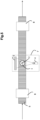
- the article is represented in the form of a bottle. It identifies a containment compartment 10 delimited by a glass wall 1 of a thickness S to be measured, an opening 11 for access to this compartment, a neck 12 which is represented by the portion of the container proximal to the opening and a bottom 13, opposite the opening 11.
- the bottle also has a body 14, which is represented by the portion of the container that continues the neck and is proximal to the bottom.
- the bottle has a development along an X-axis, which is a vertical axis in the images shown.
- a Y-axis and a Z-axis perpendicular to X and defining a Cartesian tern therewith, are also indicated.
- the method according to the invention makes it possible to assess the bottle thickness measured in the plane transverse to the X-axis.
- the method for measuring the thickness in a hollow glass article provides to have an initial source for illuminating the bottle 2, which in the following text will be referred to as "internal” since this source is adapted to emit light radiation that illuminates the inside of the bottle through the opening 11 and/or through the bottom 13.
- the images show the example with an internal illumination source placed at the opening.
- the inner radiation source 2 is chosen such that at least part of the optical emission spectrum overlaps the component of the spectrum transmitted by glass.
- the inner radiation source 2 is chosen such as to emit a radiation with a spectrum that can pass through the glass.
- the inner radiation source 2 is preferably and substantially one-dimensional, where the term one-dimensional means such that it emits a light beam that is substantially developed around the X-axis.
- the inner radiation source 2 can be a generic radiation source such as an incandescent or halogen lamp, or light-emitting diodes of either incoherent light (LED) or coherent light (LASER) can be used.
- LED incoherent light
- LASER coherent light
- the method also provides to have means emitting or reflecting light radiation outside the bottle 3.
- Such means can be at least a two-dimensional illumination source, i.e. extended in a longitudinal plane XY' relative to the bottle, external thereto, at a certain distance z' (on the Z axis) from its central axis X to illuminate the bottle in its entirety.
- the external two-dimensional source can emit any type of light radiation, as it is not required to pass through the glass.
- the external two-dimensional source can be either uniformly diffusive or collimated.
- the external light source must emit a light radiation with a lower intensity than the internal light source, for the reasons that will be explained below.
- such means can be represented by a uniformly reflective panel capable of reacting to the light emitted directly from the internal source.
- the method also provides to have image detection means 4 placed on the opposite side of the article relative to the external illumination source 3.
- image detection means 4 can be at least a video camera.
- the image detection means 4 are such as to acquire at least one image of the article in a longitudinal plane.
- the method also comprises the passage of filling the compartment 10 with a diffusive medium.
- This diffusive medium has the task of uniformly diffusing the light radiation emitted by the internal source, propagating in all directions, so as to ensure uniform illumination of the inner compartment of the bottle being examined.
- the diffusive medium must have sufficient absorbance to allow light to propagate inside the bottle but at the same time have sufficient density to make the contribution to the final image of the back wall of the bottle negligible.
- the light radiation is inserted from the bottom or opening at the mouth of the bottle and the contribution in absorption of the diffusing medium inevitably causes a dimming of the light intensity along the X-axis of the bottle.
- This diffusive medium is in the form of a gas or aerosol.
- the diffusive medium must not leave any residue inside the bottle.
- diffusive media examples include distilled water vapour or dense mists (obtained through the use of inert gases such as carbon dioxide); aerosols obtained through the vaporisation of food additives such as propylene glycol or glycerine in a distilled water solution can also be used in other embodiments.
- the absorption contribution of the diffusing medium which appears as an attenuation of the light intensity deep down in the bottle, can be limited by appropriately choosing the optical density of the diffusing medium itself and by using radiation sources from the neck of the bottle and/or from the bottom thereof that are completely independent and which may be controlled in intensity. It is also possible, in some embodiments, to widen the dynamic range of the image in order to equalise the brightness levels along the X-axis to compensate for the decrease in intensity in depth of the light in the inner area filled with the diffusive medium.
- the internal optical source 2 can be a generic radiation source or light-emitting diodes of either incoherent light (LED) or coherent light (LASER) can be used. If diodes, which are inherently narrow-band, are used, a specific operating wavelength should be chosen that can be scattered by the diffusing medium placed inside the bottle.
- LED incoherent light
- LASER coherent light
- the image acquisition means 4 must be positioned in such a way as to dominantly receive the portion of isotropic radiation scattered by the diffusing medium inside the bottle, rather than the direct radiation emitted by the internal source 2.
- the internal source 2 emits radiation in a direction perpendicular to the framing direction of the video camera; thus, for example, the internal source emits radiation along the X-axis, while the camera frames along the Z-axis.
- the internal source 2 aims to make the bottle compartment a source of uniform radiation at every point.
- the contribution related to the areas inside the bottle is mainly provided by the isotropic scattering of the radiation injected into the bottle by the internal source.
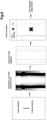
- the image of the article is processed so as to identify different brightness zones.
- the lowest brightness zones of the image correspond to those of glass (G).
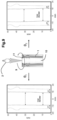
- the areas B illuminated outside the article are those with the highest brightness, while those (I) related to the inner compartment of the article have an intermediate brightness ( figure 3 ).
- the areas with the highest brightness are those referring to the contributions of light radiation outside and inside the bottle while the areas with the lowest brightness correspond to the glass.
- the areas of dimmed brightness correspond to the inner compartment of the bottle filled with the diffusive medium.
- the inner diameter of the article is measured by measuring the pixels related to the intermediate brightness areas.
- the zones corresponding to the areas outside the article could have an intermediate brightness, while the internal ones could have a higher brightness.
- the brightness level of the zones depends on the radiation emitted by the internal and external sources.
- Figure 4 shows a real result related to a bottle with an uneven thickness.
- the distortion contribution due to the lens effects of curved walls is minimised.
- Optical distortions are minimised by the fact that light is emitted from all inner portions of the volume with a uniform distribution. Further, thanks to the presence of the inner diffusing medium, the light is reflected by the entire inner compartment 10 of the bottle and thus the emitted radiation is only deflected by the glass wall that lies between the diffusing medium and the receiver.
- the bottle can be tilted relative to its longitudinal axis so that the opening points downwards.
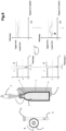
- the proposed measuring method can be implemented in a production line, that is to say, a line 5 in which the incoming empty article is filled with a diffusive medium at an initial filling station 6 using nozzles and other known instruments.
- analysis can be carried out at a subsequent measuring station 7.
- a station 8 for the extraction of the diffusive medium can also be provided downstream of the measuring station 7.
- the measuring station 7 also comprises the means to implement the described thickness measuring method.
- Such means comprise, but are not limited to: - the means of emission 3 of two-dimensional light radiation defined on a plane (XY') to illuminate externally the article by highlighting its edges; - the image acquisition means placed beyond the article relative to the two-dimensional emission means, wherein the image acquisition means are such as to acquire an image of the article on the plane (XY') - the means of emission of one-dimensional light radiation 2 placed at a neck and/or a bottom of the article and such as to illuminate the inside of the article.
- the technique set forth can be effectively used for measuring the thickness of the bottle glass and can be applied to glass of any colour and shape by choosing appropriate wavelengths of the illuminating radiation.
- a bottle rotation system is provided.
- FIG. 6 wherein the method for measuring the thickness according to the invention is schematically shown, where bottle rotation means 9 are implemented (not described in detail).
- the method consists in acquiring for different angles of rotation images of the container in a plurality of XY" planes and measuring the thickness for each image on the basis of pixel detection of the zones with the lowest brightness.
- limit values upper and lower limit
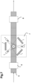
- Figure 7 shows a measuring station configuration in a bottle packaging line in which there are three video cameras and as many external sources.
- This embodiment of the method makes it possible in particular to measure the diameter of the neck, which is a particularly important value as it is decisive for the correct sealing of the bottle once in use.
- a step of processing the image is provided. This step provides to expand the dynamic range of the image in order to equalise the brightness levels along the X-axis to compensate for the decrease in intensity in depth of the light in the inner area filled with the diffusive medium.
- This correction factor must be multiplied point by point to the measurement of the inner walls, thus making it possible to properly calculate the inner diameter and the actual thickness of the glass for all depths.
- the step of processing the image can be carried out with image processing means placed on the production line itself or detached from it.
- the method described in its embodiment variants makes it possible to measure the glass thickness of an article with precision and accuracy.
- the method obtains not only the measurement of the thickness of the glass but obviously, as a consequence, also the inner diameter of the article.
- the method is applicable on any type of glass article, regardless of the colour or shape.
- the method described makes it possible to measure the thickness of the glass even of areas with a varying thickness, such as the neck in the case of the bottle, and also, in addition to the thickness of the glass, the inner diameter of these areas. Measuring the inner diameter of the neck in a bottle makes it possible to assess its correct shape and circularity, factors that ensure the cap sealing over time.
Landscapes
- Physics & Mathematics (AREA)
- General Physics & Mathematics (AREA)
- Health & Medical Sciences (AREA)
- Life Sciences & Earth Sciences (AREA)
- Chemical & Material Sciences (AREA)
- Analytical Chemistry (AREA)
- Biochemistry (AREA)
- General Health & Medical Sciences (AREA)
- Immunology (AREA)
- Pathology (AREA)
- Length Measuring Devices By Optical Means (AREA)
Applications Claiming Priority (1)
| Application Number | Priority Date | Filing Date | Title |
|---|---|---|---|
| IT102023000006597A IT202300006597A1 (it) | 2023-04-04 | 2023-04-04 | Metodo ottico per la rilevazione non distruttiva dello spessore di un contenitore cavo |
Publications (2)
| Publication Number | Publication Date |
|---|---|
| EP4443103A1 true EP4443103A1 (fr) | 2024-10-09 |
| EP4443103B1 EP4443103B1 (fr) | 2025-11-05 |
Family
ID=86852129
Family Applications (1)
| Application Number | Title | Priority Date | Filing Date |
|---|---|---|---|
| EP24167181.7A Active EP4443103B1 (fr) | 2023-04-04 | 2024-03-28 | Méthode optique pour la mesure non destructive de l'épaisseur d'un contenant creux |
Country Status (2)
| Country | Link |
|---|---|
| EP (1) | EP4443103B1 (fr) |
| IT (1) | IT202300006597A1 (fr) |
Citations (10)
| Publication number | Priority date | Publication date | Assignee | Title |
|---|---|---|---|---|
| US1016884A (en) | 1911-07-20 | 1912-02-06 | Michael Gluckman | Box for folding papers. |
| SU147327A1 (ru) * | 1961-07-28 | 1961-11-30 | Л.Е. Гуревич | Способ измерени толщины стенок стеклоизделий |
| JPS57142505A (en) | 1981-02-27 | 1982-09-03 | Nec Corp | Measuring device for inner diameter of fine tube |
| EP0320139A2 (fr) | 1987-12-08 | 1989-06-14 | Emhart Industries, Inc. | Mesure optique de l'épaisseur de la paroi d'articles transparents |
| JPH11132730A (ja) | 1997-10-30 | 1999-05-21 | Anritsu Corp | 寸法測定装置 |
| US7780898B2 (en) * | 2002-03-26 | 2010-08-24 | Agr International, Inc. | Apparatus and method for manufacturing and inspecting blow-molded plastic containers |
| DE102009025815A1 (de) | 2009-05-15 | 2010-11-25 | Degudent Gmbh | Messanordnung sowie Verfahren zum dreidimensionalen Messen eines Objektes |
| US20140029019A1 (en) | 2011-02-18 | 2014-01-30 | Msc & Sgcc | Method and device for detecting defects in material distribution in transparent containers |
| US20150276380A1 (en) | 2012-10-18 | 2015-10-01 | Msc & Sgcc | Facility for measuring the thickness of the wall of containers |
| IT202100010865A1 (it) * | 2021-04-29 | 2022-10-29 | Etrusca Vetreria | Sistema e metodo per la rilevazione di infusi in manufatti di vetro cavo |
-
2023
- 2023-04-04 IT IT102023000006597A patent/IT202300006597A1/it unknown
-
2024
- 2024-03-28 EP EP24167181.7A patent/EP4443103B1/fr active Active
Patent Citations (10)
| Publication number | Priority date | Publication date | Assignee | Title |
|---|---|---|---|---|
| US1016884A (en) | 1911-07-20 | 1912-02-06 | Michael Gluckman | Box for folding papers. |
| SU147327A1 (ru) * | 1961-07-28 | 1961-11-30 | Л.Е. Гуревич | Способ измерени толщины стенок стеклоизделий |
| JPS57142505A (en) | 1981-02-27 | 1982-09-03 | Nec Corp | Measuring device for inner diameter of fine tube |
| EP0320139A2 (fr) | 1987-12-08 | 1989-06-14 | Emhart Industries, Inc. | Mesure optique de l'épaisseur de la paroi d'articles transparents |
| JPH11132730A (ja) | 1997-10-30 | 1999-05-21 | Anritsu Corp | 寸法測定装置 |
| US7780898B2 (en) * | 2002-03-26 | 2010-08-24 | Agr International, Inc. | Apparatus and method for manufacturing and inspecting blow-molded plastic containers |
| DE102009025815A1 (de) | 2009-05-15 | 2010-11-25 | Degudent Gmbh | Messanordnung sowie Verfahren zum dreidimensionalen Messen eines Objektes |
| US20140029019A1 (en) | 2011-02-18 | 2014-01-30 | Msc & Sgcc | Method and device for detecting defects in material distribution in transparent containers |
| US20150276380A1 (en) | 2012-10-18 | 2015-10-01 | Msc & Sgcc | Facility for measuring the thickness of the wall of containers |
| IT202100010865A1 (it) * | 2021-04-29 | 2022-10-29 | Etrusca Vetreria | Sistema e metodo per la rilevazione di infusi in manufatti di vetro cavo |
Also Published As
| Publication number | Publication date |
|---|---|
| IT202300006597A1 (it) | 2024-10-04 |
| EP4443103B1 (fr) | 2025-11-05 |
Similar Documents
| Publication | Publication Date | Title |
|---|---|---|
| CA2156461C (fr) | Inspection par moyen optique des parametres dimensionnels du revetement de contenants | |
| EP1635166B1 (fr) | Inspection de la surface d'étanchéité d'un récipient | |
| KR920002176B1 (ko) | 투명 제품의 선택굴절성 결함 검출 계통 | |
| EP1481224B1 (fr) | Appareil et procede de mesures en ligne de masse ou de volume, spatialement selectives, d'articles manufactures | |
| US10491788B2 (en) | Apparatus and method for controlling the quality of transparent objects | |
| US10761033B2 (en) | Testing method and testing system | |
| US20170097306A1 (en) | Examining device and method for examining inner walls of a hollow body | |
| EP3532818B1 (fr) | Procédé et système d'inspection de lentilles de contact | |
| US20180172602A1 (en) | System and method for inspecting containers using multiple radiation sources | |
| US7595870B2 (en) | Optical inspection of container walls | |
| KR20000035255A (ko) | 용기 내의 렌즈 존재 검출 장치 및 방법 | |
| CN1119269A (zh) | 容器尺寸参数的光学检验 | |
| TW201736831A (zh) | 利用各容器之複數影像以檢測容器之系統及方法 | |
| KR20180092901A (ko) | 플라스틱 쉘 내에서의 컨택트 렌즈 검사 | |
| US5717486A (en) | Process for removing returnable containers from circulation utilizing image processing of brightness values for inspection windows | |
| EP3855174A1 (fr) | Détection et caractérisation de défauts dans des récipients pharmaceutiques cylindriques | |
| EP4443103B1 (fr) | Méthode optique pour la mesure non destructive de l'épaisseur d'un contenant creux | |
| CN110431406B (zh) | 容器的检查装置和容器的检查方法 | |
| CN114341629A (zh) | 对中空体进行光学检查的方法和装置 | |
| CN1997888A (zh) | 检验泡罩包装密封性和完整性的方法与装置 | |
| EP3968010A1 (fr) | Appareil pour l'inspection d'un élément circulaire allongé | |
| JP2024058914A (ja) | 検査方法及び検査装置 | |
| JP5256507B2 (ja) | 多層プリフォーム検査方法及び多層プリフォーム検査装置 | |
| US12422374B2 (en) | Method for monitoring the compliance of a container and apparatus thereof | |
| US20260092772A1 (en) | Method for measuring at least one cross-sectional dimension of a cylindrical hollow body |
Legal Events
| Date | Code | Title | Description |
|---|---|---|---|
| PUAI | Public reference made under article 153(3) epc to a published international application that has entered the european phase |
Free format text: ORIGINAL CODE: 0009012 |
|
| STAA | Information on the status of an ep patent application or granted ep patent |
Free format text: STATUS: THE APPLICATION HAS BEEN PUBLISHED |
|
| AK | Designated contracting states |
Kind code of ref document: A1 Designated state(s): AL AT BE BG CH CY CZ DE DK EE ES FI FR GB GR HR HU IE IS IT LI LT LU LV MC ME MK MT NL NO PL PT RO RS SE SI SK SM TR |
|
| STAA | Information on the status of an ep patent application or granted ep patent |
Free format text: STATUS: REQUEST FOR EXAMINATION WAS MADE |
|
| 17P | Request for examination filed |
Effective date: 20250407 |
|
| GRAP | Despatch of communication of intention to grant a patent |
Free format text: ORIGINAL CODE: EPIDOSNIGR1 |
|
| STAA | Information on the status of an ep patent application or granted ep patent |
Free format text: STATUS: GRANT OF PATENT IS INTENDED |
|
| RIC1 | Information provided on ipc code assigned before grant |
Ipc: G01N 21/90 20060101ALI20250428BHEP Ipc: B07C 5/34 20060101ALI20250428BHEP Ipc: B07C 5/12 20060101ALI20250428BHEP Ipc: G01B 11/27 20060101ALI20250428BHEP Ipc: G01B 11/12 20060101ALI20250428BHEP Ipc: G01B 11/10 20060101ALI20250428BHEP Ipc: G01B 11/06 20060101AFI20250428BHEP |
|
| INTG | Intention to grant announced |
Effective date: 20250530 |
|
| RAP3 | Party data changed (applicant data changed or rights of an application transferred) |
Owner name: VETRERIA ETRUSCA S.P.A. |
|
| GRAS | Grant fee paid |
Free format text: ORIGINAL CODE: EPIDOSNIGR3 |
|
| GRAA | (expected) grant |
Free format text: ORIGINAL CODE: 0009210 |
|
| STAA | Information on the status of an ep patent application or granted ep patent |
Free format text: STATUS: THE PATENT HAS BEEN GRANTED |
|
| AK | Designated contracting states |
Kind code of ref document: B1 Designated state(s): AL AT BE BG CH CY CZ DE DK EE ES FI FR GB GR HR HU IE IS IT LI LT LU LV MC ME MK MT NL NO PL PT RO RS SE SI SK SM TR |
|
| REG | Reference to a national code |
Ref country code: CH Ref legal event code: F10 Free format text: ST27 STATUS EVENT CODE: U-0-0-F10-F00 (AS PROVIDED BY THE NATIONAL OFFICE) Effective date: 20251105 Ref country code: GB Ref legal event code: FG4D |
|
| REG | Reference to a national code |
Ref country code: DE Ref legal event code: R096 Ref document number: 602024001139 Country of ref document: DE |
|
| REG | Reference to a national code |
Ref country code: IE Ref legal event code: FG4D |
|
| REG | Reference to a national code |
Ref country code: NL Ref legal event code: MP Effective date: 20251105 |
|
| PG25 | Lapsed in a contracting state [announced via postgrant information from national office to epo] |
Ref country code: ES Free format text: LAPSE BECAUSE OF FAILURE TO SUBMIT A TRANSLATION OF THE DESCRIPTION OR TO PAY THE FEE WITHIN THE PRESCRIBED TIME-LIMIT Effective date: 20251105 |
|
| REG | Reference to a national code |
Ref country code: LT Ref legal event code: MG9D |
|
| PG25 | Lapsed in a contracting state [announced via postgrant information from national office to epo] |
Ref country code: NO Free format text: LAPSE BECAUSE OF FAILURE TO SUBMIT A TRANSLATION OF THE DESCRIPTION OR TO PAY THE FEE WITHIN THE PRESCRIBED TIME-LIMIT Effective date: 20260205 |
|
| PG25 | Lapsed in a contracting state [announced via postgrant information from national office to epo] |
Ref country code: FI Free format text: LAPSE BECAUSE OF FAILURE TO SUBMIT A TRANSLATION OF THE DESCRIPTION OR TO PAY THE FEE WITHIN THE PRESCRIBED TIME-LIMIT Effective date: 20251105 Ref country code: HR Free format text: LAPSE BECAUSE OF FAILURE TO SUBMIT A TRANSLATION OF THE DESCRIPTION OR TO PAY THE FEE WITHIN THE PRESCRIBED TIME-LIMIT Effective date: 20251105 Ref country code: AT Free format text: LAPSE BECAUSE OF FAILURE TO SUBMIT A TRANSLATION OF THE DESCRIPTION OR TO PAY THE FEE WITHIN THE PRESCRIBED TIME-LIMIT Effective date: 20251105 |
|
| PGFP | Annual fee paid to national office [announced via postgrant information from national office to epo] |
Ref country code: AT Payment date: 20260301 Year of fee payment: 3 |
|
| REG | Reference to a national code |
Ref country code: AT Ref legal event code: MK05 Ref document number: 1854775 Country of ref document: AT Kind code of ref document: T Effective date: 20251105 |
|
| PG25 | Lapsed in a contracting state [announced via postgrant information from national office to epo] |
Ref country code: NL Free format text: LAPSE BECAUSE OF FAILURE TO SUBMIT A TRANSLATION OF THE DESCRIPTION OR TO PAY THE FEE WITHIN THE PRESCRIBED TIME-LIMIT Effective date: 20251105 |
|
| PG25 | Lapsed in a contracting state [announced via postgrant information from national office to epo] |
Ref country code: RS Free format text: LAPSE BECAUSE OF FAILURE TO SUBMIT A TRANSLATION OF THE DESCRIPTION OR TO PAY THE FEE WITHIN THE PRESCRIBED TIME-LIMIT Effective date: 20260205 |
|
| PG25 | Lapsed in a contracting state [announced via postgrant information from national office to epo] |
Ref country code: IS Free format text: LAPSE BECAUSE OF FAILURE TO SUBMIT A TRANSLATION OF THE DESCRIPTION OR TO PAY THE FEE WITHIN THE PRESCRIBED TIME-LIMIT Effective date: 20260305 |
|
| PG25 | Lapsed in a contracting state [announced via postgrant information from national office to epo] |
Ref country code: PT Free format text: LAPSE BECAUSE OF FAILURE TO SUBMIT A TRANSLATION OF THE DESCRIPTION OR TO PAY THE FEE WITHIN THE PRESCRIBED TIME-LIMIT Effective date: 20260305 |
|
| PG25 | Lapsed in a contracting state [announced via postgrant information from national office to epo] |
Ref country code: PL Free format text: LAPSE BECAUSE OF FAILURE TO SUBMIT A TRANSLATION OF THE DESCRIPTION OR TO PAY THE FEE WITHIN THE PRESCRIBED TIME-LIMIT Effective date: 20251105 |
|
| PG25 | Lapsed in a contracting state [announced via postgrant information from national office to epo] |
Ref country code: LV Free format text: LAPSE BECAUSE OF FAILURE TO SUBMIT A TRANSLATION OF THE DESCRIPTION OR TO PAY THE FEE WITHIN THE PRESCRIBED TIME-LIMIT Effective date: 20251105 |